Page 1213 of 5135
������
I36744
Driver Side J/BA/C Control Assembly
1
DN6
DC AM1
HTR1
DH
5
DH9
DAW±BR±W
(*3)R±W
(*4)J26 J26R±W
(*4) HHJ/C
1
CB2
CER±W
(*3)A1612
IG
I13 Ignition SW
G±Y G±R
IG1 AM1 13Center J/B
6
CA3
CGW±B
(*3)A1613
GND Center J/B
B±G
(*1)53
12
1
4D
1 2 120A ALT (*5)
1
4B
3
1 2 140A ALT
3 B±L
(*2)ED11
W
(*2)
B
(*2)
B±G
(*1)
FL MAIN
Battery
IJ IP IK *1: Gasoline
*2: 1CD±FTV
*3: LHD
*4: RHD
*5: 1AZ±FSE, 1AZ±FE
*6: 1ZZ±FE, 3ZZ±FEW±B
(*4)
A
J15
J/C W±B
(*3) IG1 Relay
Engine Room R/B No.4
Engine Room R/B No.3100A ALT (*6)
W±B
(*4)J17
J/C
AA 05±1144
± DIAGNOSTICSAIR CONDITIONING SYSTEM
AVENSIS REPAIR MANUAL (RM1018E)
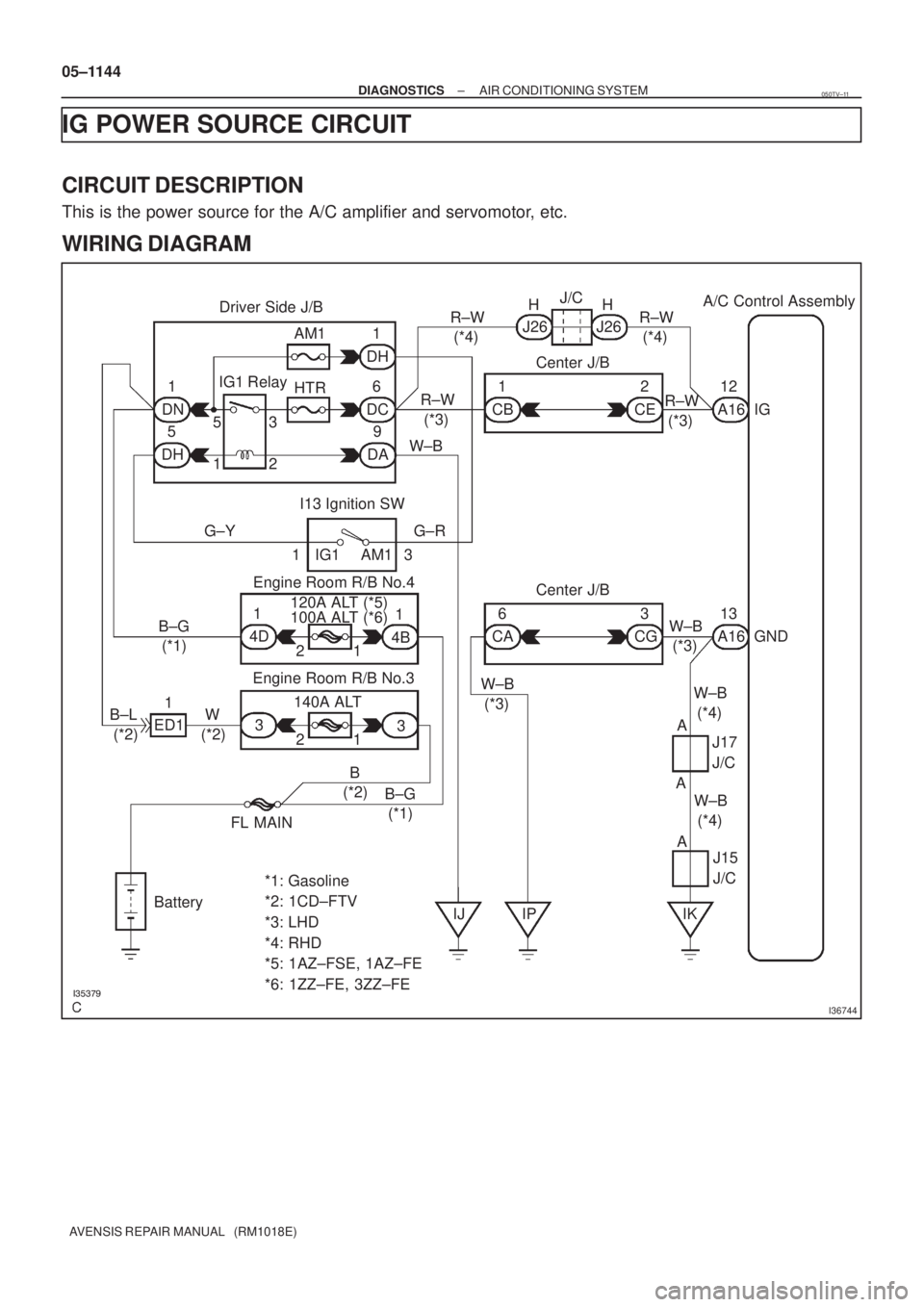
IG POWER SOURCE CIRCUIT
CIRCUIT DESCRIPTION
This is the power source for the A/C amplifier and servomotor, etc.
WIRING DIAGRAM
050TV±11
Page 1425 of 5135

2. IDENTIFICATION OF NOISE SOURCE
(a) Identify the condition under which the noise occurs, and
check the noise filter on the relat")
05±1404
± DIAGNOSTICSAUDIO SYSTEM
AVENSIS REPAIR MANUAL (RM1018E)
2. IDENTIFICATION OF NOISE SOURCE
(a) Identify the condition under which the noise occurs, and
check the noise filter on the related part.
Condition in which noise occursNoise Source
Depressing the acceleration pedal increases noise, and stopping the engine
erases the noise immediately.Generator
Noise occurs during the A/C or the heater operation.Blower motor
Rapid acceleration while driving on the unpaved road or after the IG switch is
turned ON makes noise.Fuel pump
Pressing and then releasing the horn switch, and keeping pressing the horn
switch makes unusual noise.Horn
Stopping the engine erases small noise that has been heard.Ignition
Noise occurs synchronously with the turn signal flash.Flasher
Noise occurs during the window washer operation.Washer
Noise occurs during the engine running, and it continues after the engine
stops.Engine coolant temperature sensor
Noise occurs during the wiper operation.Wiper
Noise occurs when the brake pedal is depressed.Stop light switch
Others.Static electricity stored on the vehicle
(b) Reference:
�Make sure first that there is no noise from outside.
Failing to do so makes the noise source detection
difficult and leads to misunderstanding.
�The noise should be removed in descending order
of loudness.
�Setting the radio untuned makes noise noticeable,
making the recognition of the phenomenon easier.
Page 1475 of 5135

NOISE OCCURS
INSPECTION PROCEDURE
1 CHECK OF SPEAKER INSTALLATION
(a) Check the speaker installation condition.
(1) Check that eac")
± DIAGNOSTICSAUDIO SYSTEM
05±1419
AVENSIS REPAIR MANUAL (RM1018E)
NOISE OCCURS
INSPECTION PROCEDURE
1 CHECK OF SPEAKER INSTALLATION
(a) Check the speaker installation condition.
(1) Check that each speaker is securely installed.
Standard: Malfunction disappears.
HINT:
The radio is equipped with the noise prevention system that works against only the excessively large noise,
thereby excessively large noise do not occur in the radio. If large noise occurs, check whether or not the earth
on the antenna installation part and the proper noise±prevention equipment are all installed, and whether
or not the improper wiring is held.
Condition in which noise occursNoise type
Depressing the acceleration pedal increases noise, and stopping the engine
erases the noise immediately.Alternator noise
Noise occurs during the A/C or the heater operation.Blower motor noise
Rapid acceleration during the drive on the unpaved road or after the IG
switch is turned ON makes noise.Fuel pump noise
Pressing and then releasing the horn switch, and keeping pressing the horn
switch makes noise.Horn noise
Stopping the engine erases the small noise that has been heard.Ignition noise
Noise occurs in turn with the blink of the turn signal flash.Flasher noise
Noise occurs during the window washer operation.Washer noise
Noise occurs during the engine running, and it continues to occur after the
engine is stopped.Water temperature sensor noise
Noise occurs during the wiper operation.Wiper noise
Noise occurs when the brake pedal is depressed.Stop light switch noise
Others.Static electricity on the vehicle
HINT:
�Identify the condition under which the noise occurs, and check the noise filter on the related part.
�Make sure first that there is no noise from outside. Failing to do so makes the noise occurrence source
detection impossible and leads to misunderstanding.
�The noise should be removed in descending order of loudness.
NG INSTALL IT PROPERLY
OK
IDENTIFICATION OF NOISE SOURCE
054A1±09
Page 1558 of 5135
B70496
Front Door w/ Motor
Lock Assy LH
Front Door Courtesy
Lamp Switch Assy
Rear Door w/ Motor
Lock Assy LH
Rear Door Courtesy
Lamp Switch AssyFront Door Courtesy
Lamp Switch Assy
Rear Door w/ Motor
Lock Assy RH
Rear Door Courtesy
Lamp Switch Assy Front Door w/ Motor
Lock Assy RH
Sedan Models
Wagon Models Liftback Models
Back Door Lock Assy Power Window Regulator Master Switch Assy
� Door Control SwitchBack Door Lock Assy
Back Door Opener Switch Assy
(Outside Handle Switch)
Back Door Lock Assy
Back Door Opener Switch Assy
(Outside Handle Switch)Back Door Opener Switch Assy
(Outside Handle Switch)
± DIAGNOSTICSPOWER DOOR LOCK CONTROL SYSTEM
05±1541
AVENSIS REPAIR MANUAL (RM1018E)
Page 1562 of 5135
ItemDiagnostic
Note Normal Condition Measurement Item/Display
(Range)
DOOR HANDLE SW
Back door opener switch sig")
05±1538
± DIAGNOSTICSPOWER DOOR LOCK CONTROL SYSTEM
AVENSIS REPAIR MANUAL (RM1018E)ItemDiagnostic
Note Normal Condition Measurement Item/Display
(Range)
DOOR HANDLE SW
Back door opener switch signal
(Outside handle switch)
/ON or OFFON: Back door opener switch is pushed
OFF: Back door opener switch is not pushed±
LOCK STATUSBack door position switch signal
/UNLOCK or LOCKUNLOCK: Back door is unlock
LOCK: Back door is lock±
4. ACTIVE TEST
HINT:
Performing the ACTIVE TEST using the hand±held tester allows you to operate the relay, VSV, actuator,
etc. without parts removal. Performing the ACTIVE TEST as the first step of troubleshooting is one way to
shorten the labor time. It is possible to display the DATA LIST during the ACTIVE TEST.
(a) Connect the hand±held tester to the DLC3.
(b) Turn the ignition switch ON.
(c) According to the display on the tester, perform the ACTIVE TEST.
Standard (Integration relay):
ItemTest DetailsDiagnostic Note
DOOR LOCKOperate door lock motor for all doors LOCK/OFF±
DOOR LOCKOperate door lock motor for all doors UNLOCK/OFF±
Page 1589 of 5135
B66771
KSW
W±B8 U1
Unlock Warning Switch Assy
W±B
IP5
+B GROUND 1
W±R W±B
2
1Instrument Panel J/B Assy
PRG
RDA 16
2PRG
RDA D6
Door Control Receiver
7Integration
Relay
IC2 I14 3 G±Y
L±W 16
7
To
Battery
DA Y
IO*
1
6 8
Center
J/BIC2 G±Y
L±W
CA CD
AJ16
J/C LHD Models
19 I14
A W±B
IL*
2*1: Gasoline Engine
*2: 1CD±FTV
± DIAGNOSTICSWIRELESS DOOR LOCK CONTROL SYSTEM
05±1575
AVENSIS REPAIR MANUAL (RM1018E)
ONLY WIRELESS CONTROL FUNCTION DOES NOT OPERATE
(PREPARE NEW OR NORMAL TRANSMITTER OF THE SAME
TYPE VEHICLE)
CIRCUIT DESCRIPTION
The door control receiver receives a signal from the transmitter and sends this signal to the integration relay.
Then, the integration relay controls door operation by sending a door LOCK/UNLOCK signal and a luggage
door (back door) unlock signal to each door lock motor.
WIRING DIAGRAM
05BNB±01
Page 1602 of 5135
B66777
Front Door w/ Motor
Lock Assy LH
Front Door Courtesy
Lamp Switch
Rear Door w/ Motor
Lock Assy LH
Rear Door Courtesy
Lamp SwitchFront Door Courtesy
Lamp Switch
Rear Door w/ Motor
Lock Assy RH
Rear Door Courtesy
Lamp Switch Front Door w/ Motor
Lock Assy RH
w/ Motor Luggage Compartment
Door Lock Assy (Luggage
Compartment Door Lock)
Sedan
Wagon Liftback
w/ Motor Back Door Lock Assy
(Back Door Lock Assy)
w/ Motor Back Door Lock Assy
(Back Door Lock Assy)
± DIAGNOSTICSWIRELESS DOOR LOCK CONTROL SYSTEM
05±1571
AVENSIS REPAIR MANUAL (RM1018E)
Page 1605 of 5135
05±1560
±
DIAGNOSTICS POWER DOOR LOCK CONTROL SYSTEM
AVENSIS REPAIR MANUAL (RM1018E)
DOUBLE LOCK FUNCTION DOES NOT OPERATE PROPERLY
CIRCUIT DESCRIPTION
RHD Models w/ Double Lock Only:
All the doors except the back door have the double locking system. This\
system is set and unset by the
integration relay. When the integration relay receives a request signal from the wireless transmitter (See
page 73±1) to set or unset the double locking system, it drives the double lock \
motor built into each door
lock according to the condition of all the double lock position switches, th\
us causing the double locking sys-
tem to be set and unset.
05C8D±01


DOUBLE LOCK FUNCTION DOES NOT OPERATE PROPERLY
CIRCUIT DESCRIPTION
RHD Models w/ Double Lock Only:
All the door")