Page 2608 of 5135
F40024
A
B
G23166
32±60
±
BRAKE SPEED SENSOR FRONT LH
AVENSIS REPAIR MANUAL (RM1018E)
(b)Install the sensor harness clamp with the 2 bolts ºAº and ºBº to the body and shock absorber.
Torque:
Bolt A: 8.0 N �m (82 kgf �cm, 71 in. �lbf)
Bolt B: 29 N �m (296 kgf �cm, 21 ft �lbf)
NOTICE:
Do not twist the sensor wire when installing the sensor.
(c)Connect the speed sensor connector.
(d)Connect the resin clip and speed sensor wire harness to the body and clamp.
5.INSTALL FRONT FENDER LINER LH
6.INSTALL FRONT WHEEL Torque: 103 N �m (1,050 kgf �cm, 76 ft �lbf)
7.CHECK ABS SPEED SENSOR SIGNAL (See page 05±699)
Page 2610 of 5135

F42292
F42290
To
Master
Cylinder
FrontTo Master
Cylinder
Rear
To Rear
Wheel RH
To Front Wheel LHTo Front Wheel RH
To Rear
Wheel LH
AA
A
A
BB
32±58
±
BRAKE BRAKE ACTUATOR ASSY (W/ VSC)
AVENSIS REPAIR MANUAL (RM1018E)
5. REMOVE BRAKE ACTUATOR ASSY
(a) Remove the 3 bolts and brake actuator from the brake acutuator bracket.
6. REMOVE OIL PRESSURE SENSOR
7. REMOVE SKID CONTROL ECU
(a) Disconnect the connector from the skid control ECU.
(b) Using a torx driver (T20), remove the 6 screws and the skid control EC\
U from the brake actuator.
8. INSTALL SKID CONTROL ECU
(a) Install the skid control ECU and 6 screws with a torx driver (T20).
(b) Connect the connector to the skid control ECU.
9. INSTALL OIL PRESSURE SENSOR
10. INSTALL BRAKE ACTUATOR ASSY
(a) Install the brake actuator with 3 the bolts to the brake actuator bracke\
t. Torque: 4.7 N �m (48 kgf �cm, 42 in. �lbf)
11. INSTALL BRAKE ACTUATOR WITH BRACKET
(a) Install the brake actuator with bracket with the nut and 2 bolts.
Torque: 19 N �m (194 kgf �cm, 14 ft �lbf)
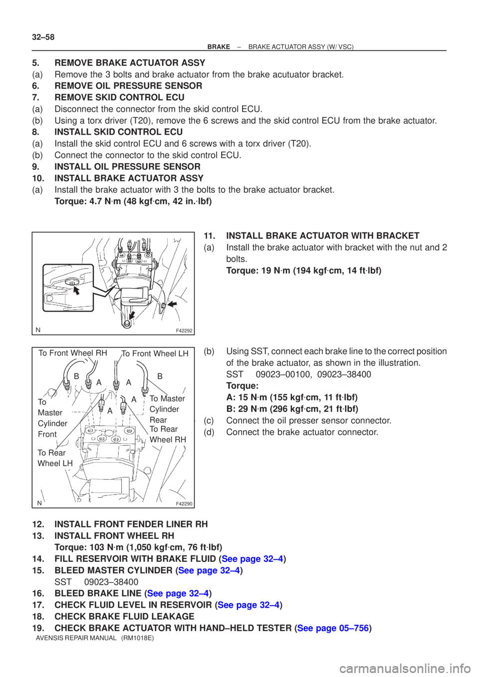
(b) Using SST, connect each brake line to the correct position of the brake actuator, as shown in the illustration.
SST 09023±00100, 09023±38400
Torque:
A: 15 N �m (155 kgf �cm, 11 ft �lbf)
B: 29 N �m (296 kgf �cm, 21 ft �lbf)
(c) Connect the oil presser sensor connector.
(d) Connect the brake actuator connector.
12. INSTALL FRONT FENDER LINER RH
13. INSTALL FRONT WHEEL RH Torque: 103 N �m (1,050 kgf �cm, 76 ft �lbf)
14.FILL RESERVOIR WITH BRAKE FLUID (See page 32±4)
15.BLEED MASTER CYLINDER (See page 32±4) SST 09023±38400
16.BLEED BRAKE LINE (See page 32±4)
17.CHECK FLUID LEVEL IN RESERVOIR (See page 32±4)
18. CHECK BRAKE FLUID LEAKAGE
19.CHECK BRAKE ACTUATOR WITH HAND±HELD TESTER (See page 05±756)
Page 2613 of 5135

G24213
To Master Cylinder Front
G24212
To Master Cylinder Rear
To Front Wheel RH
To Rear Wheel LH
To Rear Wheel RH
To Front Wheel LH
±
BRAKE BRAKE ACTUATOR ASSY(W/O VSC)
32±55
AVENSIS REPAIR MANUAL (RM1018E)
5.REMOVE BRAKE ACTUATOR ASSY
(a)Remove the 2 nuts and brake actuator from the brake acutuator bracket.
6.REMOVE SKID CONTROL ECU
(a)Disconnect the connector from the skid control ECU.
(b)Using a torx driver (T20), remove the 4 screws and the skid control EC\
U from the brake actuator.
7.INSTALL SKID CONTROL ECU
(a)Install the skid control ECU and 4 screws with a torx driver (T20).
(b)Connect the connector to the skid control ECU.
8.INSTALL BRAKE ACTUATOR ASSY
(a)Install the brake actuator with the 2 nuts to the brake actuator bracket\
.
Torque: 7.0 N �m ( 71 kgf �cm, 62 in. �lbf)
9.INSTALL BRAKE ACTUATOR WITH BRACKET
(a)Install the brake actuator with bracket with the nut and 2 bolts.
Torque: 19 N �m (194 kgf �cm, 14 ft �lbf)
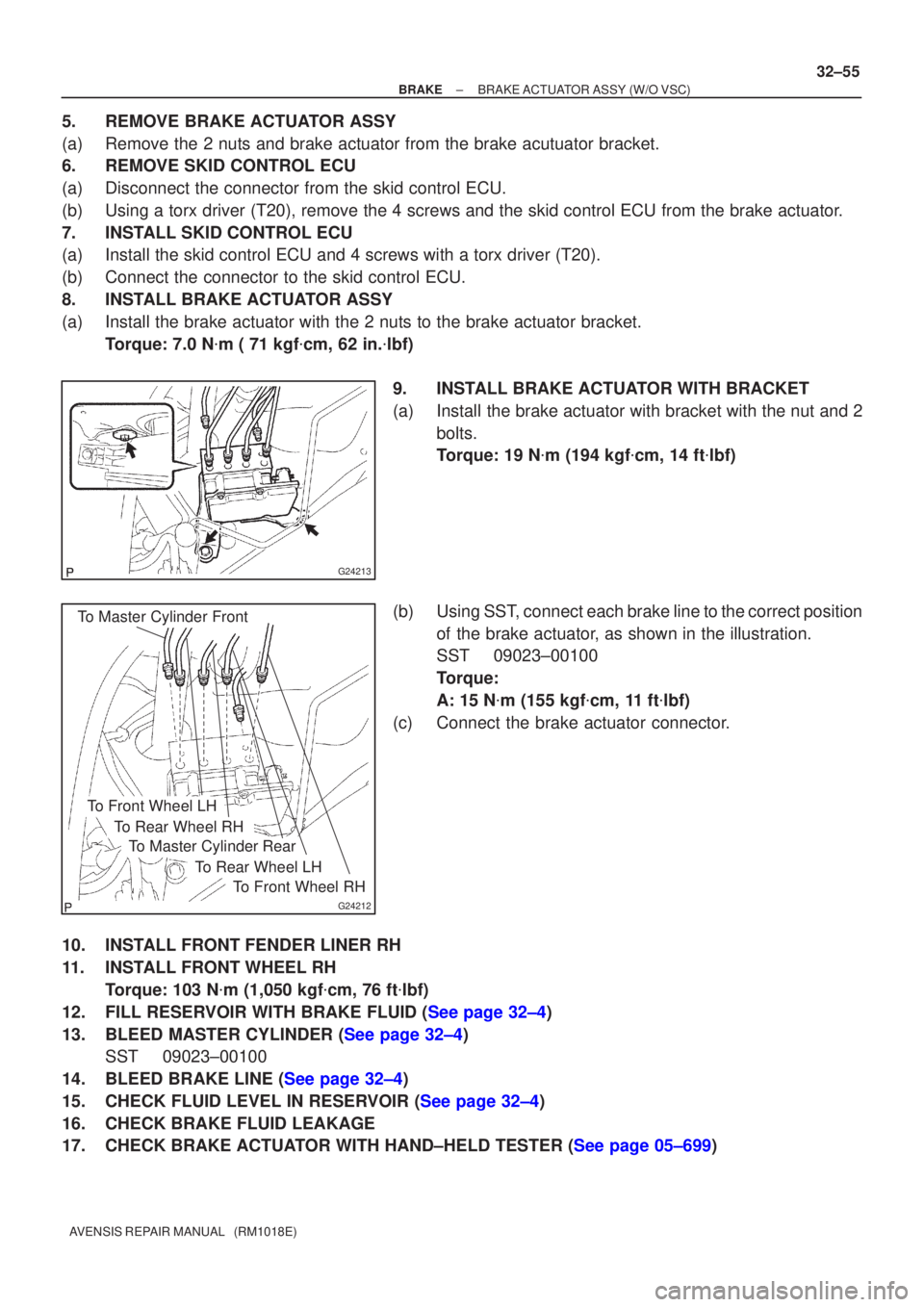
(b)Using SST, connect each brake line to the correct position of the brake actuator, as shown in the illustration.
SST09023±00100
Torque:
A: 15 N �m (155 kgf �cm, 11 ft �lbf)
(c)Connect the brake actuator connector.
10.INSTALL FRONT FENDER LINER RH
11.INSTALL FRONT WHEEL RH Torque: 103 N �m (1,050 kgf �cm, 76 ft �lbf)
12.FILL RESERVOIR WITH BRAKE FLUID (See page 32±4)
13.BLEED MASTER CYLINDER (See page 32±4) SST 09023±00100
14.BLEED BRAKE LINE (See page 32±4)
15.CHECK FLUID LEVEL IN RESERVOIR (See page 32±4)
16. CHECK BRAKE FLUID LEAKAGE
17.CHECK BRAKE ACTUATOR WITH HAND±HELD TESTER (See page 05±699)
Page 2620 of 5135
32±52
± BRAKEREAR BRAKE
AVENSIS REPAIR MANUAL (RM1018E)
33. CHECK BRAKE FLUID LEAKAGE
34. INSTALL REAR WHEEL
Torque: 103 N�m (1,050 kgf�cm, 76 ft�lbf)
Page 2626 of 5135

F45419
Cylinder Slide Pin
Lithium soap base glycol grease
F45421
Union Bolt
±
BRAKE FRONT BRAKE
32±45
AVENSIS REPAIR MANUAL (RM1018E)
24. INSTALL FRONT DISC BRAKE CYLINDER SLIDE PIN
KIT
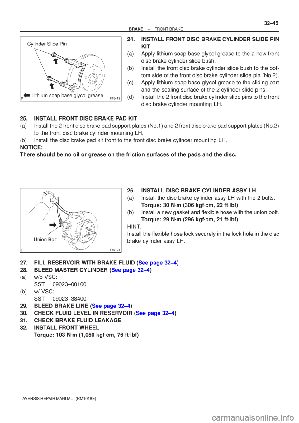
(a) Apply lithium soap base glycol grease to the a new front
disc brake cylinder slide bush.
(b) Install the front disc brake cylinder slide bush to the bot- tom side of the front disc brake cylinder slide pin (No.2).
(c) Apply lithium soap base glycol grease to the sliding part
and the sealing surface of the 2 cylinder slide pins.
(d) Install the 2 front disc brake cylinder slide pins to the front disc brake cylinder mounting LH.
25. INSTALL FRONT DISC BRAKE PAD KIT
(a) Install the 2 front disc brake pad support plates (No.1) and 2 front disc bra\
ke pad support plates (No.2) to the front disc brake cylinder mounting LH.
(b) Install the disc brake pad kit front to the front disc brake cylinder mo\
unting LH.
NOTICE:
There should be no oil or grease on the friction surfaces of the pads an\
d the disc.
26. INSTALL DISC BRAKE CYLINDER ASSY LH
(a) Install the disc brake cylinder assy LH with the 2 bolts.Torque: 30 N �m (306 kgf �cm, 22 ft �lbf)
(b) Install a new gasket and flexible hose with the union bolt.
Torque: 29 N �m (296 kgf �cm, 21 ft �lbf)
HINT:
Install the flexible hose lock securely in the lock hole in the disc
brake cylinder assy LH.
27.FILL RESERVOIR WITH BRAKE FLUID (See page 32±4)
28.BLEED MASTER CYLINDER (See page 32±4)
(a) w/o VSC: SST 09023±00100
(b) w/ VSC: SST 09023±38400
29.BLEED BRAKE LINE (See page 32±4)
30.CHECK FLUID LEVEL IN RESERVOIR (See page 32±4)
31. CHECK BRAKE FLUID LEAKAGE
32. INSTALL FRONT WHEEL
Torque: 103 N �m (1,050 kgf �cm, 76 ft �lbf)
Page 2641 of 5135

F45057
w/o VSC:
w/ VSC:
To Master
Cylinder Rear
To
Master
Cylinder
Front
To Rear Wheel
RH
To Front Wheel LH
To Front Wheel RH
To Rear Wheel
LH
A
To
Master
Cylinder
FrontTo Master
Cylinder
Rear
To Rear
Wheel RH
To Front Wheel LHTo Front Wheel RH
To Rear
Wheel LH
AA
AA
BB
C80806
±
BRAKE BRAKE BOOSTER ASSY (RHD)
32±31
AVENSIS REPAIR MANUAL (RM1018E)
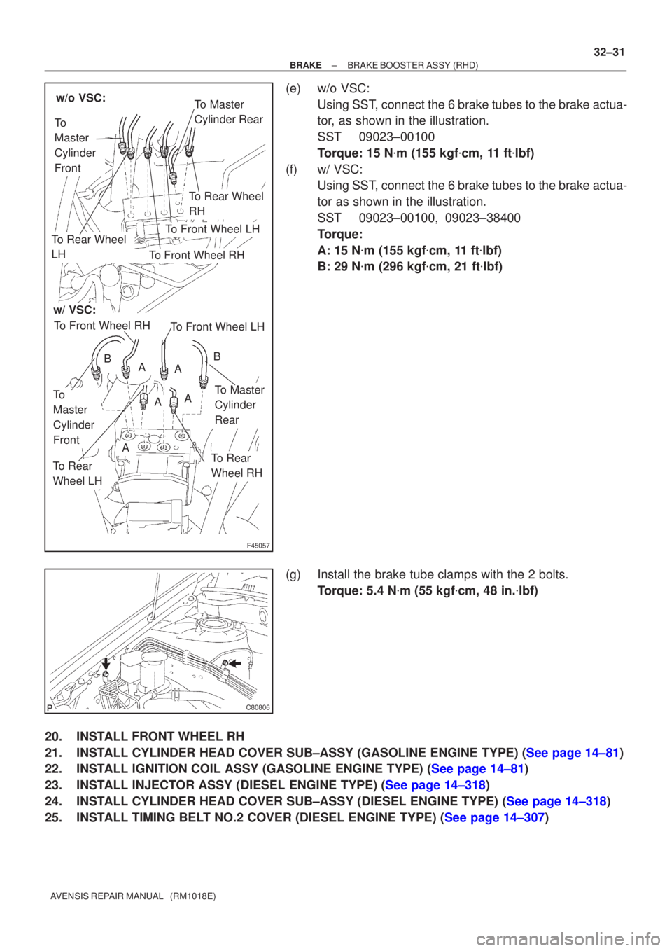
(e) w/o VSC:
Using SST, connect the 6 brake tubes to the brake actua-
tor, as shown in the illustration.
SST 09023±00100
Torque: 15 N �m (155 kgf �cm, 11 ft �lbf)
(f) w/ VSC: Using SST, connect the 6 brake tubes to the brake actua-
tor as shown in the illustration.
SST 09023±00100, 09023±38400
Torque:
A: 15 N �m (155 kgf �cm, 11 ft �lbf)
B: 29 N �m (296 kgf �cm, 21 ft �lbf)
(g) Install the brake tube clamps with the 2 bolts. Torque: 5.4 N �m (55 kgf �cm, 48 in. �lbf)
20. INSTALL FRONT WHEEL RH
21.INSTALL CYLINDER HEAD COVER SUB±ASSY (GASOLINE ENGINE TYPE) (See page 14±81)
22.INSTALL IGNITION COIL ASSY (GASOLINE ENGINE TYPE) (See page 14±81)
23.INSTALL INJECTOR ASSY (DIESEL ENGINE TYPE) (See page 14±318)
24.INSTALL CYLINDER HEAD COVER SUB±ASSY (DIESEL ENGINE TYPE) (See page 14±318)
25.INSTALL TIMING BELT NO.2 COVER (DIESEL ENGINE TYPE) (See page 14±307)
Page 2655 of 5135
F44823
RH
LH
Front
Front
F44708
Expand
Contract 33±18
± PARKING BRAKEPARKING BRAKE ASSY
AVENSIS REPAIR MANUAL (RM1018E)
16. CHECK PARKING BRAKE INSTALLATION
(a) Check that each part is installed properly.
NOTICE:
There should be no oil or grease on the friction surface of the shoe lining and disc.
17. INSTALL REAR DISC
18. ADJUST PARKING BRAKE SHOE CLEARANCE
(a) Temporarily install the hub nuts.
(b) Remove the hole plug, and turn the adjuster and expand
the shoes until the disc locks.
(c) Contract the shoe adjuster until the disc can rotate
smoothly.
Standard : Return 8 notches
(d) Check that there is no brake drag.
(e) Install the hole plug.
19. CONNECT REAR DISC BRAKE CALIPER ASSY LH
(a) Install the rear disc brake caliper with the 2 bolts.
Torque: 47 N�m (475 kgf�cm, 34 ft�lbf)
20. INSTALL REAR WHEEL
Torque: 103 N�m (1,050 kgf�cm, 76 ft�lbf)
Page 2660 of 5135
33±12
±
PARKING BRAKE PARKING BRAKE CABLE ASSY NO.3
AVENSIS REPAIR MANUAL (RM1018E)
17.APPLY HIGH TEMPERATURE GREASE (See page 33±14)
18.INSTALL PARKING BRAKE SHOE LEVER LH (See page 33±14)
19.INSTALL PARKING BRAKE SHOE KIT (See page 33±14) SST 09718±00010
20.INSTALL PARKING BRAKE SHOE ADJUSTING SCREW SET (See page 33±14)
21.INSTALL PARKING BRAKE ADJUSTER KIT (See page 33±14)
22. INSTALL REAR DISC
23.CONNECT REAR DISC BRAKE CALIPER ASSY LH(See page 30±31)
24.ADJUST PARKING BRAKE SHOE CLEARANCE(See page 33±14)
25. INSTALL REAR WHEEL Torque: 103 N �m (1,050 kgf �cm, 76 ft �lbf)
26.SETTLING PARKING BRAKE SHOES AND DISC (See page 33±14)
27.INSPECT PARKING BRAKE LEVER TRAVEL (See page 33±2)
28.ADJUST PARKING BRAKE LEVER TRAVEL (See page 33±2)
29. CHECK EXHAUST LEAKAGE