Page 2573 of 5135
G23881
������G25777
G23871
±
REAR SUSPENSION REAR SUSPENSION ARM ASSY NO.1 LH
27±23
AVENSIS REPAIR MANUAL (RM1018E)
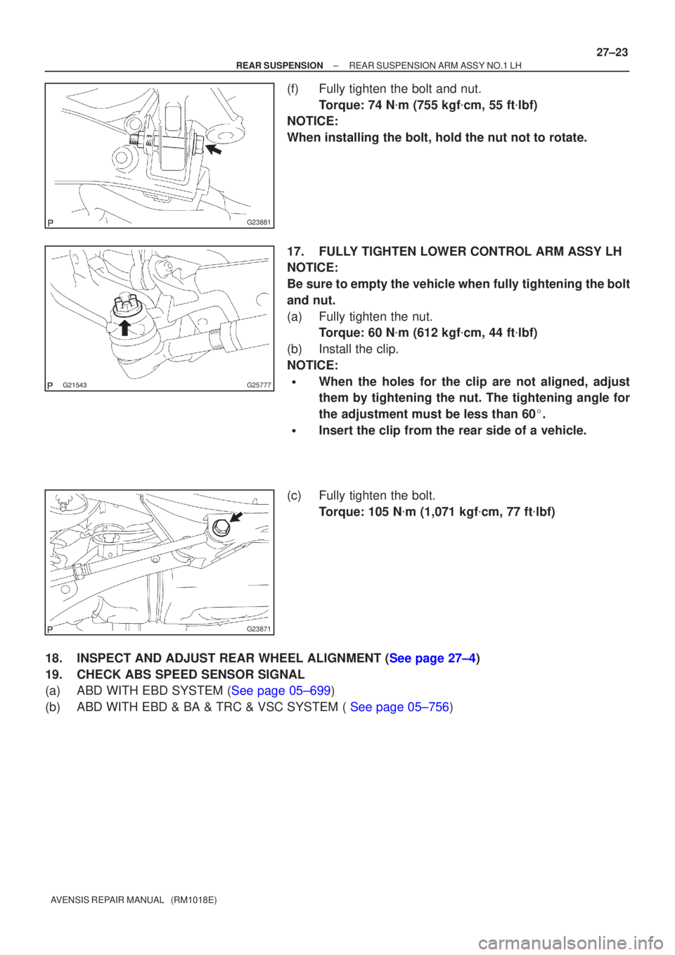
(f) Fully tighten the bolt and nut.
Torque: 74 N �m (755 kgf �cm, 55 ft �lbf)
NOTICE:
When installing the bolt, hold the nut not to rotate.
17. FULLY TIGHTEN LOWER CONTROL ARM ASSY LH
NOTICE:
Be sure to empty the vehicle when fully tightening the bolt
and nut.
(a) Fully tighten the nut. Torque: 60 N �m (612 kgf �cm, 44 ft �lbf)
(b) Install the clip.
NOTICE:
�When the holes for the clip are not aligned, adjust
them by tightening the nut. The tightening angle for
the adjustment must be less than 60 �.
�Insert the clip from the rear side of a vehicle.
(c) Fully tighten the bolt. Torque: 105 N �m (1,071 kgf �cm, 77 ft �lbf)
18.INSPECT AND ADJUST REAR WHEEL ALIGNMENT (See page 27±4)
19. CHECK ABS SPEED SENSOR SIGNAL
(a)ABD WITH EBD SYSTEM (See page 05±699)
(b)ABD WITH EBD & BA & TRC & VSC SYSTEM ( See page 05±756)
Page 2579 of 5135

AVENSIS REPAIR MANUAL (RM1018E)
15. INSTALL BRAKE BOOSTER ASSY
(a) Install the brake booster assy with the 4 nuts. Torque: 13 N �m (130 kgf �cm")
F42620
F40019
32±20
±
BRAKE BRAKE BOOSTER ASSY (LHD)
AVENSIS REPAIR MANUAL (RM1018E)
15. INSTALL BRAKE BOOSTER ASSY
(a) Install the brake booster assy with the 4 nuts. Torque: 13 N �m (130 kgf �cm, 9 ft �lbf)
(b) Install the clevis pin and clip to the brake master cylinder clevis.
(c) Connect the vacuum hose to the brake booster assy.
16. CONNECT FRONT BRAKE TUBE NO.5
(a) Using SST and spanner, connect the brake tube to the flexible hose.
SST 09023±00100
Torque: 15 N �m (155 kgf �cm, 11 ft �lbf)
17. INSTALL FRONT WHEEL LH Torque: 103 N �m (1,050 kgf �cm, 76 ft �lbf)
18.INSTALL HEATER ASSY (W/ COLD AREA) (See page 55±100)
19.INSTALL BRAKE MASTER CYLINDER SUB±ASSY (See page 32±13)
(a) w/o VSC: SST 09023±00100
(b) w/ VSC: SST 09023±38400
20. INSTALL CHARCOAL CANISTER ASSY (GASOLINE ENGINE TYPE)
21.INSTALL FUEL FILTER ASSY (DIESEL ENGINE TYPE) (See page 11±82)
22. CONNECT ENGINE ROOM RELAY BLOCK
23. INSTALL AIR CLEANER ASSEMBLY WITH HOSE
24.FILL RESERVOIR WITH BRAKE FLUID (See page 32±4)
25.BLEED MASTER CYLINDER (See page 32±4)
(a) w/o VSC:
SST 09023±00100
(b) w/ VSC: SST 09023±38400
26.BLEED BRAKE LINE (See page 32±4)
27.BLEED CLUTCH PIPE LINE (M/T TRANSAXLE) (See page 42±13)
28.CHECK AND ADJUST BRAKE PEDAL HEIGHT (See page 32±6)
29.CHECK PEDAL FREE PLAY (See page 32±6)
30.CHECK PEDAL RESERVE DISTANCE (See page 32±6)
31. CHECK FUEL LEAK
32.CHECK FLUID LEVEL IN RESERVOIR (See page 32±4)
33. CHECK BRAKE FLUID LEAKAGE
Page 2594 of 5135
F42258
G24222
± BRAKEBRAKE FLUID
32±5
AVENSIS REPAIR MANUAL (RM1018E)
3. BLEED BRAKE LINE
(a) Connect the vinyl tube to the brake caliper.
(b) Depress the brake pedal several times, then loosen the
bleeder plug with the pedal depressed.
(c) At the point when the fluid stops, coming out tighten the
bleeder plug, then release the brake pedal.
(d) Repeat (b) and (c) until all the air in the fluid has been bled
out.
(e) Repeat the above procedure to bleed the air out of the
brake line for each wheel.
Torque: 10 N�m (102 kgf�cm, 7 ft.�lbf)
4. CHECK FLUID LEVEL IN RESERVOIR
(a) Check the fluid level and add fluid if necessary.
Fluid: SAE J1704 or FMVSS No. 116 DOT4
Page 2598 of 5135

REAR AXLE LH HUB BOLT
REPLACEMENT")
300K0±01
������F45577
Hold
Turn
SST
������F45578
Hold
Turn
Nut
Washer
30±36
±
DRIVE SHAFT / PROPELLER SHAFT REAR AXLE LH HUB BOLT
AVENSIS REPAIR MANUAL (RM1018E)
REAR AXLE LH HUB BOLT
REPLACEMENT
HINT:
�COMPONENTS: See page 30±30
�Replace the RH side by the same procedures as the LH side.
1. REMOVE REAR WHEEL
2. SEPARATE REAR DISC BRAKE CALIPER ASSY LH
(a) Removing the 2 bolts and rear disc brake caliper assy.
NOTICE:
Use a string or other device to keep the brake caliper from hanging down\
.
3. REMOVE REAR DISC
4. REMOVE REAR AXLE LH HUB BOLT
(a) Turn the axle hub to move the LH hub bolt and SST, thatare to be removed, to the place shown in the illustration.
NOTICE:
Do not replace the hub bolt in any places other than that in
the illustration.
(b) Using SST and a hammer handle or an equivalent to hold the axle hub, remove the LH hub bolt.
SST 09628±10011
5. INSTALL REAR AXLE LH HUB BOLT
(a) Install a washer and nut to a new LH hub bolt as shown in the illustration.
(b) Using a hammer handle or an equivalent to hold the axle
hub, install the LH hub bolt by torquing the nut.
6. INSTALL REAR DISC
7. INSTALL REAR DISC BRAKE CALIPER ASSY LH
(a) Install the rear disc brake caliper assy with the 2 bolts. Torque: 47 N �m (475 kgf �cm, 34 ft �lbf)
8. INSTALL REAR WHEEL Torque: 103 N �m (1,050 kgf �cm, 76 ft �lbf)
Page 2602 of 5135

19.TEMPORARILY TIGHTEN LOWER CONTROL ARM ASSY LH
(a)Temporarily tigh")
G21543
F44820
������F45267
30±34
±
DRIVE SHAFT / PROPELLER SHAFT REAR AXLE CARRIER SUB±ASSY LH
AVENSIS REPAIR MANUAL (RM1018E)
19.TEMPORARILY TIGHTEN LOWER CONTROL ARM ASSY LH
(a)Temporarily tighten the lower control arm assy with the
nut.
Temporarily tighten Torque:
7 ± 13 N �m (71 ± 133 kgf �cm, 5.1 ± 9.6 ft �lbf)
20.CONNECT PARKING BRAKE CABLE ASSY NO.3
(a)Connect the parking brake cable assy No.3 to the backing plate.
21.INSTALL PARKING BRAKE SHOE LEVER LH (See page 33±14)
22.INSTALL PARKING BRAKE SHOE KIT (See page 33±14) SST 09718±00010
23.INSTALL PARKING BRAKE SHOE ADJUSTING SCREW SET (See page 33±14)
24.INSTALL PARKING BRAKE ADJUSTER KIT (See page 33±14)
25.CHECK PARKING BRAKE INSTALLATION (See page 33±14)
26.INSPECT BEARING BACKLASH (See page 30±2)
27.INSPECT AXLE HUB DEVIATION (See page 30±2)
28. INSTALL REAR DISC
29.ADJUST PARKING BRAKE SHOE CLEARANCE (See page 33±14)
30. INSTALL REAR DISC BRAKE CALIPER ASSY LH
(a) Install the rear disc brake caliper with the 2 bolts. Torque: 47 N �m (475 kgf �cm, 34 ft �lbf)
31. CONNECT SKID CONTROL SENSOR WIRE
(a) Connect the skid control sensor wire with the bolt. Torque: 5.0 N �m (51 kgf �cm, 44 in. �lbf)
(b) Connect the connector.
HINT:
Do not twist the sensor wire when installing the sensor.
32. INSTALL REAR WHEEL Torque: 103 N �m (1,050 kgf �cm, 76 ft �lbf)
33.STABILIZE SUSPENSION (See page 27±8)
Page 2603 of 5135

34. FULLY TIGHTEN UPPER CONTROL ARM ASSY
(a) Fully tighten the bolt.
Torque: 74 N �m (755 kgf �")
±
DRIVE SHAFT / PROPELLER SHAFT REAR AXLE CARRIER SUB±ASSY LH
30±35
AVENSIS REPAIR MANUAL (RM1018E)
34. FULLY TIGHTEN UPPER CONTROL ARM ASSY
(a) Fully tighten the bolt.
Torque: 74 N �m (755 kgf �cm, 55 ft �lbf)
NOTICE:
When installing the bolt, hold the nut not to rotate.
35. FULLY TIGHTEN REAR SUSPENSION ARM ASSY NO.1 LH
(a) Fully tighten the nut (ball joint side). Torque: 105 N �m (1,071 kgf �cm, 77 ft �lbf)
(b) Install the clip.
NOTICE:
If the holes for the clip are not aligned, tighten the nut up to 60 � further.
(c) Fully tighten the bolt and nut.
Torque: 74 N �m (755 kgf �cm, 55 ft �lbf)
NOTICE:
When installing the bolt, hold the nut not to rotate.
36. FULLY TIGHTEN LOWER CONTROL ARM ASSY LH
(a) Fully tighten the nut. Torque: 60 N �m (612 kgf �cm, 44 ft �lbf)
(b) Install the clip.
NOTICE:
If the holes for the clip are not aligned, tighten the nut up to 60 � further.
(c) Fully tighten the bolt (member side). Torque: 105 N �m (1,071 kgf �cm, 77 ft �lbf)
NOTICE:
When installing the bolt, hold the nut not to rotate.
37.INSPECT AND ADJUST PARKING BRAKE LEVER TRAVEL (See page 33±2)
38.INSPECT AND ADJUST REAR WHEEL ALIGNMENT (See page 27±4)
39. CHECK ABS SPEED SENSOR SIGNAL
(a)ABD WITH EBD SYSTEM (See page 05±699)
(b)ABD WITH EBD & BA & TRC & VSC SYSTEM ( See page 05±756)
Page 2606 of 5135

7. INSTALL SKID CONTROL SENSOR
(a) Clean the contacting surface of the axle hub and that of a new skid co")
G23168
F08658
SST
G23167
32±62
±
BRAKE SKID CONTROL SENSOR
AVENSIS REPAIR MANUAL (RM1018E)
7. INSTALL SKID CONTROL SENSOR
(a) Clean the contacting surface of the axle hub and that of a new skid control sensor.
NOTICE:
Make sure the sensor rotor is clean.
(b) Place the skid control sensor on the axle hub so that the connector comes into the most downward position under
the on vehicle condition.
(c) Using SST and a press, install the skid control sensor to the axle hub.
NOTICE:
�Do not tap the skid control sensor directly with a ham-
mer.
�Check that there is no foreign matter on the skid con-
trol sensor detection portion.
�Press in the skid control sensor straight and slowly.
SST 09830±36010, 09950±60010 (09951±00650), 09950±70010 (09951±07100)
8.INSTALL REAR AXLE HUB & BEARING ASSY LH (See page 30±31)
9. INSTALL REAR BRAKE DRUM SUB±ASSY
(a) Aligning the matchmarks, install the rear disc.
10. INSTALL REAR DISC BRAKE CALIPER ASSY LH
(a) Install the rear disc brake caliper assy LH with the 2 bolts. Torque: 47 N �m (475 kgf �cm, 34 ft �lbf)
11. CONNECT SKID CONTROL SENSOR WIRE
(a) Connect the connector from the skid control sensor.
12. INSTALL REAR WHEEL Torque: 103 N �m (1,050 kgf �cm, 76 ft �lbf)
13.INSPECT AND ADJUST REAR WHEEL ALIGNMENT (See page 27±4)
14.CHECK ABS SPEED SENSOR SIGNAL (See page 05±699)
Page 2607 of 5135
3201P±05
G23166
F40024
G23165
G23165
± BRAKESPEED SENSOR FRONT LH
32±59
AVENSIS REPAIR MANUAL (RM1018E)
SPEED SENSOR FRONT LH
REPLACEMENT
HINT:
Replace the RH side by using the same procedures as those for the LH side.
1. REMOVE FRONT WHEEL
2. REMOVE FRONT FENDER LINER LH
3. REMOVE SPEED SENSOR FRONT LH
(a) Disconnect the resin clip and speed sensor wire harness
from the body and clamp.
(b) Disconnect the speed sensor connector.
(c) Remove the 2 clamp bolts holding the sensor harness
from the body and shock absorber.
(d) Remove the bolt and separate the speed sensor front LH.
NOTICE:
Prevent foeingn matter from attaching to the sensor tip.
4. INSTALL SPEED SENSOR FRONT LH
(a) Install the speed sensor front LH with the bolt.
Torque: 8.0 N�m (82 kgf�cm, 71 in.�lbf)
NOTICE:
Prevent foeingn matter from attaching to the sensor tip.

3. BLEED BRAKE LINE
(a) Connect the vinyl tube to the brake caliper.
(b) Depress the brake pedal several times, then loosen th")

SPEED SENSOR FRONT LH
REPLACEMENT
HINT:
Replace the RH side by using the same procedures as")