Page 5002 of 5135
![TOYOTA AVENSIS 2005 Service Repair Manual 05KAP–02
– DIAGNOSTICSELECTRONIC CONTROLLED AUTOMATIC
TRANSAXLE [ECT] (U341E) (From February, 2004)05–221
AVENSIS REPAIR MANUAL SUPPLEMENT
(RM1098E)
MECHANICAL SYSTEM TESTS
1. PERFORM MECHANICAL TOYOTA AVENSIS 2005 Service Repair Manual 05KAP–02
– DIAGNOSTICSELECTRONIC CONTROLLED AUTOMATIC
TRANSAXLE [ECT] (U341E) (From February, 2004)05–221
AVENSIS REPAIR MANUAL SUPPLEMENT
(RM1098E)
MECHANICAL SYSTEM TESTS
1. PERFORM MECHANICAL](/manual-img/14/57441/w960_57441-5001.png)
05KAP–02
– DIAGNOSTICSELECTRONIC CONTROLLED AUTOMATIC
TRANSAXLE [ECT] (U341E) (From February, 2004)05–221
AVENSIS REPAIR MANUAL SUPPLEMENT
(RM1098E)
MECHANICAL SYSTEM TESTS
1. PERFORM MECHANICAL SYSTEM TESTS
(a) Measure the stall speed.
The object of this test is to check the overall performance of the transaxle and engine by measuring
the stall speeds in the D and R positions.
NOTICE:
�Perform the test at the normal operating ATF (Automatic Transmission Fluid) temperature 50
to 80�C (122 to 176�F).
�Do not continuously run this test for longer than 10 seconds.
�To ensure safety, do this test in a wide, clear level area which provides good traction.
�The stall test should always be carried out in pairs. One technician should observe the condi-
tions of wheels or wheel stoppers outside the vehicle while the other is doing the test.
(1) Chock the 4 wheels.
(2) Connect an Intelligent Tester II to the DLC3.
(3) Fully apply the parking brake.
(4) Keep your left foot pressed firmly on the brake pedal.
(5) Start the engine.
(6) Shift into the D position. Press all the way down on the accelerator pedal with your right foot.
(7) Quickly read the stall speed at this time.
Stall speed: 2,400 � 150 rpm
(8) Do the same test in the R position.
Stall speed: 2,400 � 150 rpm
Evaluation:
ProblemPossible cause
(a) Stall engine speed is low in D and R positions
�Engine power output may be insufficient
�Stator one–way clutch not operating properly
HINT: If the value is less than the specified value by 600 rpm or
more, the torque converter could be faulty.
(b) Stall engine speed is high in D position
�Line pressure is too low
�Forward clutch slipping
�One–way clutch No.2 not operating properly
(c) Stall engine speed is high in R position
�Line pressure is too low
�Reverse clutch slipping
�1st and reverse brake slipping
(d) Stall engine speed is high in D and R positions�Line pressure is too low
�Improper fluid level
Page 5065 of 5135

A96566
A93669
14–46–
ENGINE MECHANICAL CYLINDER HEAD GASKET (1ZZ–FE/3ZZ–FE)(From
February, 2004)
AVENSIS REPAIR MANUAL SUPPLEMENT
(RM1098E)
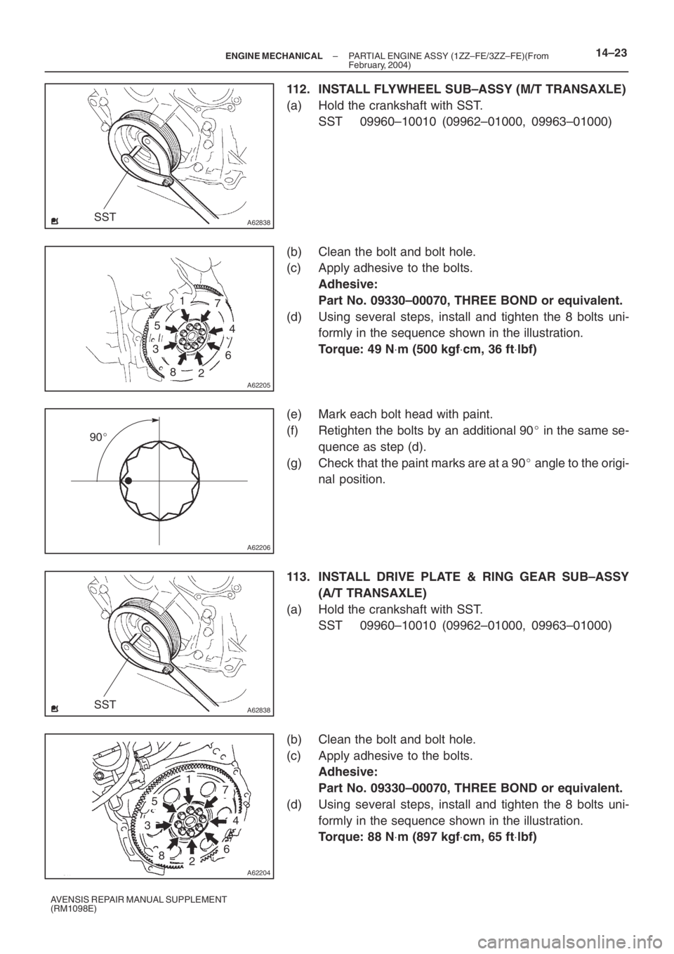
76. INSTALL V–RIBBED IDLER ASSY NO.1
(a) Install the tube and idler with the nut and bolt.
Torque: 39 N ⋅m (400 kgf ⋅cm, 29 ft ⋅lbf)
77. INSTALL FAN AND GENERATOR V BELT
(See Pub. No. RM1018E on page 14–5)
78. INSTALL AIR CLEANER HOSE NO.1
Torque: 1.5 N ⋅m (15 kgf ⋅cm, 13 in. ⋅lbf)
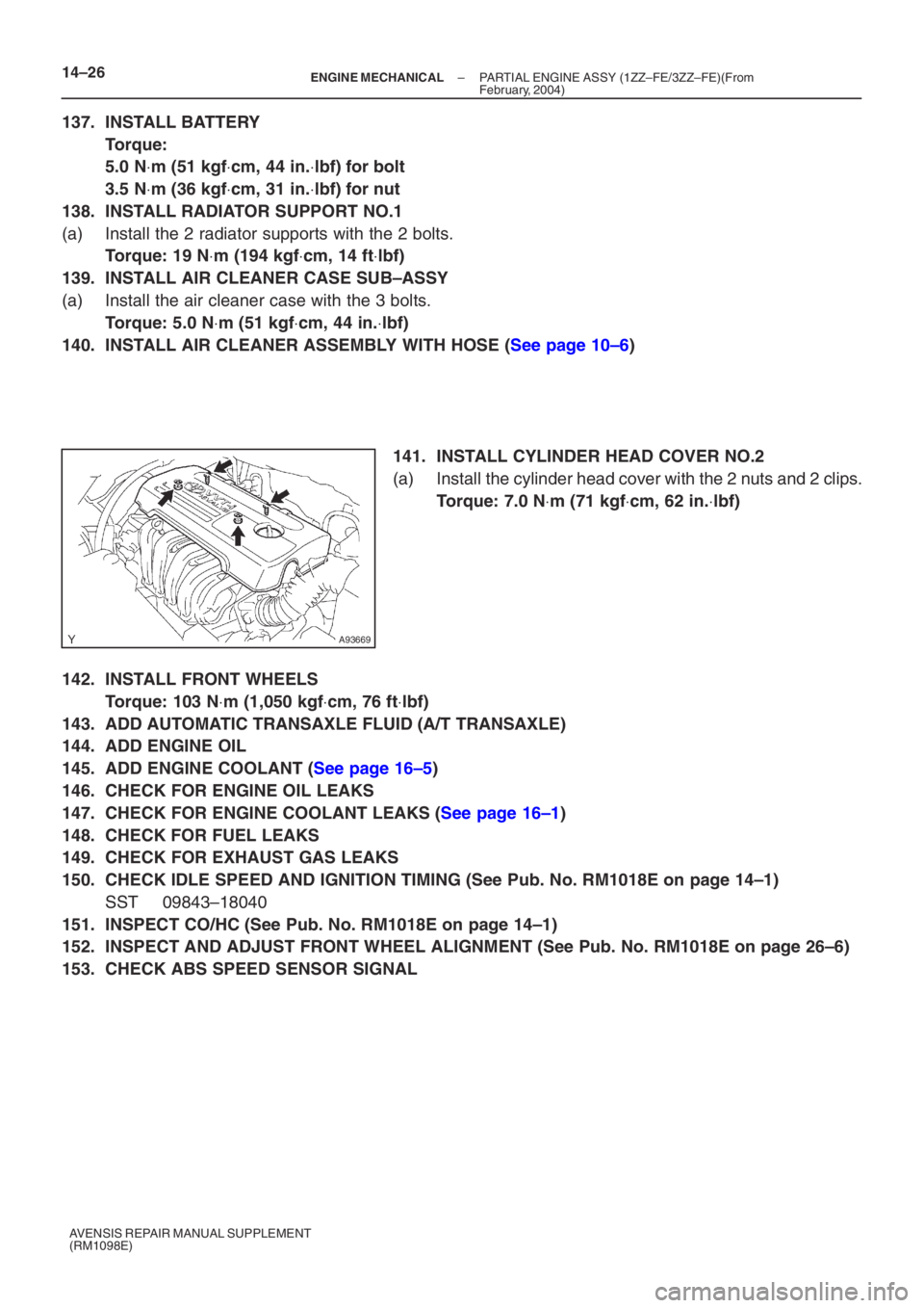
79. INSTALL CYLINDER HEAD COVER NO.2
(a) Install the cylinder head cover with the 2 nuts and 2 clips.
Torque: 7.0 N ⋅m (71 kgf ⋅cm, 62 in. ⋅lbf)
80. INSTALL FRONT WHEEL RH
Torque: 103 N ⋅m (1,050 kgf ⋅cm, 76 ft ⋅lbf)
81. ADD ENGINE COOLANT (See page 16–5)
82. INSPECT COMPRESSION (See Pub. No. RM1018E on page 14–1)
SST 09992–00500
83. INSPECT CO/HC (See Pub. No. RM1018E on page 14–1)
84. INSPECT IGNITION TIMING (See Pub. No. RM1018E on page 14–1)
SST 09843–18040
85. CHECK FOR ENGINE COOLANT LEAKS (See page 16–1)
86. CHECK FOR ENGINE OIL LEAKS
87. CHECK FOR EXHAUST GAS LEAKS
Page 5080 of 5135

A62838SST
A62205
1
5
3
82
6
4
7
A62206
90�
A62838SST
A62204
1
5
3
82
6
4
7
– ENGINE MECHANICALPARTIAL ENGINE ASSY (1ZZ–FE/3ZZ–FE)(From
February, 2004)14–23
AVENSIS REPAIR MANUAL SUPPLEMENT
(RM1098E)
112. INSTALL FLYWHEEL SUB–ASSY (M/T TRANSAXLE)
(a) Hold the crankshaft with SST.
SST 09960–10010 (09962–01000, 09963–01000)
(b) Clean the bolt and bolt hole.
(c) Apply adhesive to the bolts.
Adhesive:
Part No. 09330–00070, THREE BOND or equivalent.
(d) Using several steps, install and tighten the 8 bolts uni-
formly in the sequence shown in the illustration.
Torque: 49 N⋅m (500 kgf⋅cm, 36 ft⋅lbf)
(e) Mark each bolt head with paint.
(f) Retighten the bolts by an additional 90� in the same se-
quence as step (d).
(g) Check that the paint marks are at a 90� angle to the origi-
nal position.
113. INSTALL DRIVE PLATE & RING GEAR SUB–ASSY
(A/T TRANSAXLE)
(a) Hold the crankshaft with SST.
SST 09960–10010 (09962–01000, 09963–01000)
(b) Clean the bolt and bolt hole.
(c) Apply adhesive to the bolts.
Adhesive:
Part No. 09330–00070, THREE BOND or equivalent.
(d) Using several steps, install and tighten the 8 bolts uni-
formly in the sequence shown in the illustration.
Torque: 88 N⋅m (897 kgf⋅cm, 65 ft⋅lbf)
Page 5083 of 5135

A93669
14–26–
ENGINE MECHANICAL PARTIAL ENGINE ASSY (1ZZ–FE/3ZZ–FE)(From
February, 2004)
AVENSIS REPAIR MANUAL SUPPLEMENT
(RM1098E)
137. INSTALL BATTERY
Torque:
5.0 N ⋅m (51 kgf ⋅cm, 44 in. ⋅lbf) for bolt
3.5 N ⋅m (36 kgf ⋅cm, 31 in. ⋅lbf) for nut
138. INSTALL RADIATOR SUPPORT NO.1
(a) Install the 2 radiator supports with the 2 bolts.
Torque: 19 N ⋅m (194 kgf ⋅cm, 14 ft ⋅lbf)
139. INSTALL AIR CLEANER CASE SUB–ASSY
(a) Install the air cleaner case with the 3 bolts.
Torque: 5.0 N ⋅m (51 kgf ⋅cm, 44 in. ⋅lbf)
140. INSTALL AIR CLEANER ASSEMBLY WITH HOSE (See page 10–6)
141. INSTALL CYLINDER HEAD COVER NO.2
(a) Install the cylinder head cover with the 2 nuts and 2 clips.
Torque: 7.0 N ⋅m (71 kgf ⋅cm, 62 in. ⋅lbf)
142. INSTALL FRONT WHEELS
Torque: 103 N ⋅m (1,050 kgf ⋅cm, 76 ft ⋅lbf)
143. ADD AUTOMATIC TRANSAXLE FLUID (A/T TRANSAXLE)
144. ADD ENGINE OIL
145. ADD ENGINE COOLANT (See page 16–5)
146. CHECK FOR ENGINE OIL LEAKS
147. CHECK FOR ENGINE COOLANT LEAKS (See page 16–1)
148. CHECK FOR FUEL LEAKS
149. CHECK FOR EXHAUST GAS LEAKS
150. CHECK IDLE SPEED AND IGNITION TIMING (See Pub. No. RM1018E on page 14–1)
SST 09843–18040
151. INSPECT CO/HC (See Pub. No. RM1018E on page 14–1)
152. INSPECT AND ADJUST FRONT WHEEL ALIGNMENT (See Pub. No. RM1018E on page \
26–6)
153. CHECK ABS SPEED SENSOR SIGNAL