Page 2828 of 5135
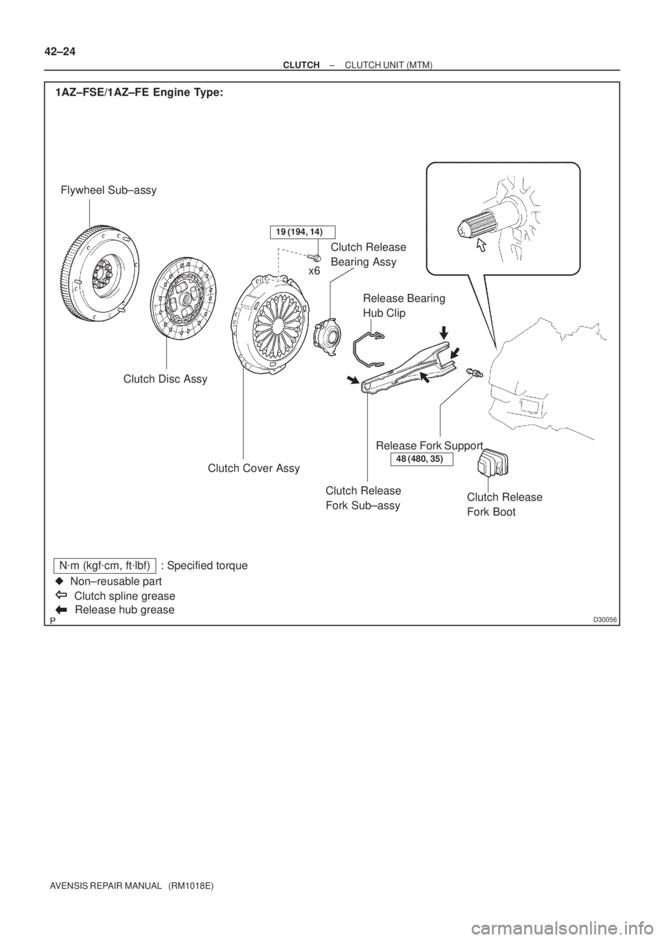
D30056Release hub grease
N�m (kgf�cm, ft�lbf) : Specified torque
�Non±reusable part
Clutch spline grease 1AZ±FSE/1AZ±FE Engine Type:
Flywheel Sub±assy
Clutch Disc Assy
Clutch Release
Fork Sub±assy Clutch Cover AssyRelease Bearing
Hub Clip Clutch Release
Bearing Assy
Release Fork Support
Clutch Release
Fork Boot
48 (480, 35)
19 (194, 14)
x6 42±24
± CLUTCHCLUTCH UNIT (MTM)
AVENSIS REPAIR MANUAL (RM1018E)
Page 2829 of 5135
D30057
1CD±FTV Engine Type:
Flywheel Sub±assyClutch Disc Assy
Clutch Release Fork Sub±assy Clutch Cover Assy
Release Bearing
Hub Clip Clutch Release
Bearing Assy
Release Fork Support
Clutch Release
Fork Boot
37 (375, 27)
19 (194, 14)
x6
Release hub grease
N�m (kgf�cm, ft�lbf) : Specified torque
�Non±reusable part
Clutch spline grease
± CLUTCHCLUTCH UNIT (MTM)
42±25
AVENSIS REPAIR MANUAL (RM1018E)
Page 2851 of 5135

50. INSTALL HEIGHT CONTROL SENSOR SUB±ASS")
������
������D30705
LHD:
A
B
RHD:
Matchmarks
Matchmarks
A
B
±
POWER STEERING RACK & PINION POWER STEERING GEAR ASSY
51±45
AVENSIS REPAIR MANUAL (RM1018E)
50. INSTALL HEIGHT CONTROL SENSOR SUB±ASSY FR RH (W/ DISCHARGE HEAD LAMP)
(See page 65±28)
51.INSTALL TIE ROD END SUB±ASSY LH (See page 30±6)
52. INSTALL TIE ROD END SUB±ASSY RH
HINT:
Perform the same procedure on the other side.
53. INSTALL FRONT WHEELS
Torque: 103 N �m (1,050 kgf �cm, 76 ft �lbf)
54. INSTALL STEERING COLUMN HOLE COVER SUB±ASSY NO.1
55. INSTALL STEERING INTERMEDIATE SHAFT ASSYNO.2
(a) Align the matchmarks on the intermediate shaft assy No.2 and the intermediate shaft.
(b) Install the bolt B and tighten the bolt A. Torque: 35 N �m (360 kgf �cm, 26 ft �lbf)
56.INSTALL COLUMN HOLE COVER SILENCER SHEET (See page 50±9)
57. INSTALL CYLINDER HEAD COVER SUB±ASSY
58.ADD POWER STEERING FLUID (See page 51±4)
59.BLEED POWER STEERING FLUID (See page 51±4)
60.CHECK POWER STEERING FULUID LEVEL IN RESERVER (See page 51±4)
61. INSPECT FLUID LEAK
62.INSPECT HOOD SUB±ASSY (See page 75±2)
63.ADJUST HOOD SUB±ASSY (See page 75±2)
64.INSPECT AND ADJUST FRONT WHEEL ALIGNMENT (See page 26±6)
65. INSTALL ENGINE UNDER COVER LH
66. INSTALL ENGINE UNDER COVER RH
67.HEADLIGHT AIM ONLY (W/ DISCHARGE HEAD LAMP) (See page 65±19)
Page 2854 of 5135

OVERHAUL
NOTICE:
When installing, coat the parts indicat")
510DJ±02
D25320
No.1 Engine HangerNo.2 Engine Hanger
Front:Rear:
51±28
±
POWER STEERING STEERING GEAR ASSY
AVENSIS REPAIR MANUAL (RM1018E)
OVERHAUL
NOTICE:
When installing, coat the parts indicated by the arrows with power steering fluid or molybdenum dis-
ulfide lithium base grease (See page 51±27).
1. INSPECT CENTER FRONT WHEEL
2.REMOVE COLUMN HOLE COVER SILENCER SHEET (See page 50±9)
3.SEPARATE STEERING INTERMEDIATE SHAFT ASSY NO.2 (See page 51±36)
4. SEPARATE STEERING COLUMN HOLE COVER SUB±ASSY NO.1
5. REMOVE FRONT WHEELS
6. REMOVE ENGINE UNDER COVER LH
7. REMOVE ENGINE UNDER COVER RH
8.SEPARATE TIE ROD END SUB±ASSY LH (See page 30±6) SST 09628±62011
9. SEPARATE TIE ROD END SUB±ASSY RH SST 09628±62011
HINT:
Perform the same procedure on the other side.
10. REMOVE HEIGHT CONTROL SENSOR SUB±ASSY FR RH (W/ DISCHARGE HEAD LAMP)\
(See page 65±28)
11.SEPARATE FRONT STABILIZER LINK ASSY LH (See page 30±6)
12. SEPARATE FRONT STABILIZER LINK ASSY RH
HINT:
Perform the same procedure on the other side.
13.SEPARATE FRONT SUSPENSION ARM SUB±ASSY LOWER NO.1 LH (See page 30±6)
14. SEPARATE FRONT SUSPENSION ARM SUB±ASSY LOWER NO.1 RH
HINT:
Perform the same procedure on the other side.
15. REMOVE HOOD SUB±ASSY
16. REMOVE CYLINDER HEAD COVER SUB±ASSY
17. SUSPEND ENGINE ASSEMBLY
(a) Remove the 2 PCV hoses.
(b) Install the 2 engine hangers in the correct direction.No.1 engine hanger: 12281±22021
No.2 engine hanger: 12281±15040
Bolt: 90512±B1016
Torque: 38 N �m (387 kgf �cm, 28 ft �lbf)
(c) Attach the engine chain hoist to the hangers.
CAUTION:
Do not attempt t hang the ingine by hooking the chain to
any other part.
18.REMOVE FRONT SUSPENSION CROSSMEMBER SUB±ASSY (See page 51±36)
19. REMOVE STEERING COLUMN HOLE COVER SUB±ASSY NO.1
Page 2859 of 5135

46.INSTALL FRONT SUSPENSION ARM SUB±ASSY LOWER NO.1 LH (See page 30±6)
47. INSTALL FRONT SUSPENSION ARM SUB±ASSY LOWER")
±
POWER STEERING STEERING GEAR ASSY
51±33
AVENSIS REPAIR MANUAL (RM1018E)
46.INSTALL FRONT SUSPENSION ARM SUB±ASSY LOWER NO.1 LH (See page 30±6)
47. INSTALL FRONT SUSPENSION ARM SUB±ASSY LOWER NO.1 RH
HINT:
Perform the same procedure on the other side.
48.INSTALL FRONT STABILIZER LINK ASSY LH (See page 30±6)
49. INSTALL FRONT STABILIZER LINK ASSY RH
HINT:
Perform the same procedure on the other side.
50. INSTALL HEIGHT CONTROL SENSOR SUB±ASSY FR RH (W/ DISCHARGE HEAD LAMP)
(See page 65±28)
51.INSTALL TIE ROD END SUB±ASSY LH (See page 30±6)
52. INSTALL TIE ROD END SUB±ASSY RH
HINT:
Perform the same procedure on the other side.
53. INSTALL FRONT WHEELS Torque: 103 N �m (1,050 kgf �cm, 76 ft �lbf)
54. INSTALL STEERING COLUMN HOLE COVER SUB±ASSY NO.1
55.INSTALL STEERING INTERMEDIATE SHAFT ASSY NO.2 (See page 51±36)
56.INSTALL COLUMN HOLE COVER SILENCER SHEET (See page 50±9)
57. INSTALL CYLINDER HEAD COVER SUB±ASSY
58.INSPECT HOOD SUB±ASSY (See page 75±2)
59.ADJUST HOOD SUB±ASSY (See page 75±2)
60.INSPECT AND ADJUST FRONT WHEEL ALIGNMENT (See page 26±6)
61. INSTALL ENGINE UNDER COVER LH
62. INSTALL ENGINE UNDER COVER RH
63.HEADLIGHT AIM ONLY (W/ DISCHARGE HEAD LAMP) (See page 65±19)
Page 2878 of 5135
±
POWER STEERING VANE PUMP ASSY (AZ Series)
51±17
AVENSIS REPAIR MANUAL (RM1018E)
37. CONNECT OIL RESERVOIR TO PUMP HOSE NO.1
(a) Connect the oil reservoir to pump hose No.1 with the clip.
NOTICE:
Take care not to spill fluid on the V belt.
38. INSTALL FAN AND GENERATOR V BELT
1AZ±FE: (See page 14±105)
1AZ±FSE: (See page 14±185)
39. INSTALL ENGINE UNDER COVER RH
40. INSTALL FRONT WHEEL RH Torque: 103 N �m (1,050 kgf �cm, 76 ft �lbf)
41.ADD POWER STEERING FLUID (See page 51±4)
42.BLEED POWER STEERING FLUID (See page 51±4)
43.CHECK POWER STEERING FULUID LEVEL IN RESERVER (See page 51±4)
44. INSPECT FLUID LEAK
Page 2883 of 5135

Open
Lock Position
F08858
±
POWER STEERING POWER STEERING SYSTEM
51±7
AVENSIS REPAIR MANUAL (RM1018E)
(k) With the engine idling and valve fully ope")
Z15500
Oil
ReservoirPS Vane
Pump
PS Gear
SST(s)
Open
Lock Position
F08858
±
POWER STEERING POWER STEERING SYSTEM
51±7
AVENSIS REPAIR MANUAL (RM1018E)
(k) With the engine idling and valve fully opened, turn the
steering wheel to full lock position.
Minimum fluid pressure:
AZ Series:
8,300 to 9,000 kPa (85 to 92 kgf/cm
2, 1,204 to 1,305 psi)
1CD±FTV:
8,800 to 9,500 kPa (90 to 97 kgf/cm
2, 1,276 to 1,378 psi)
NOTICE:
�Do not maintain lock position for more than 10 se-
conds.
�Do not let the fluid temperature become too high.
(l) Remove SST(s).
(m) AZ Series:
Connect the pressure feed tube assy to the vane pump
assy (See page 51±9).
(n) 1CD±FTV:
Connect the pressure feed tube assy to the vane pump
assy (See page 51±19).
(o) Bleed the power steering system.
5. CHECK STEERING EFFORT
(a) Center the steering wheel.
(b)Remove the steering wheel pad (See page 60±17).
(c) Start the engine and run it at idle.
(d) Measure the steering effort in both directions. Steering effort (Reference):
5.5 N´m (56 kgf´cm, 49 in.´lbf)
HINT:
Take the tire type, pressure and contact surface into consider-
ation before making your diagnosis.
(e) Torque the steering wheel set nut. Torque: 50 N´m (510 kgf´cm, 37 ft´lbf)
(f)Install the steering wheel pad (See page 60±17).
Page 2980 of 5135
H43003
H42615
60±18
±
SUPPLEMENTAL RESTRAINT SYSTEM HORN BUTTON ASSY
AVENSIS REPAIR MANUAL (RM1018E)
4. INSTALL HORN BUTTON ASSY
(a) Support the horn button assy with the hand as shown in the illustration.
(b) Connect the airbag connectors.
(c) Connect the horn connector.
(d) Confirm that the circumference groove of the torx screw fits in the screw case, and place the horn button assy onto
the steering wheel assy.
(e) Using a torx socket wrench (T 30), install the 2 screws. Torque: 8.8 N �m (90 kgf �cm, 78 in. �lbf)
5.INSPECT HORN BUTTON ASSY (See page 60±11)
(a) Do a visual check which includes the following items with the horn button assy installed in the vehicle:
Cuts, minute cracks or marked discoloration on the horn
button assy top surface and in the grooved portion.
6.INSPECT SRS WARNING LIGHT (See page 05±1184)


51±17
AVENSIS REPAIR MANUAL (RM1018E)
37. CONNECT OIL RESERVOIR TO PUMP HOSE NO.1
(a) Connect the oil reservoir to pump hose No.1 with the clip.
NOTICE:")

4. INSTALL HORN BUTTON ASSY
(a) Support the horn button assy with the hand as shown in the illu")