Page 2668 of 5135
3300F±07
F44808
Lock NutAdjusting Nut
33±2
±
PARKING BRAKE PARKING BRAKE SYSTEM
AVENSIS REPAIR MANUAL (RM1018E)
ADJUSTMENT
1. REMOVE REAR WHEEL
2.ADJUST PARKING BRAKE SHOE CLEARANCE (See page 33±14)
3. INSTALL REAR WHEEL Torque: 103 N �m (1,050 kgf �cm, 76 ft �lbf)
4. INSPECT PARKING BRAKE LEVER TRAVEL
(a) Pull the parking brake lever all the way up, and count the number of cli\
cks. Parking brake lever travel: 6 ± 9 clicks at 196 N (20 kgf, 44.1 lbf)\
5. ADJUST PARKING BRAKE LEVER TRAVEL
(a) Remove the console box assy RR.(See page71±11)
(b) Loosen the lock nut and turn the adjusting nut until the le- ver travel turns correct.
(c) Tighten the lock nut. Torque: 5.0 N �m (51 kgf �cm, 44 in. �lbf)
(d) Install the console box assy RR.
(See page 71±11)
Page 2694 of 5135

AVENSIS REPAIR MANUAL (RM1018E)
11. SEPARATE CONNECTOR
(a) Separate the 2 wire harnesse clamps")
D30342
D30343
D30346
D30344
40±26
±
AUTOMATIC TRANSMISSION / TRANS AUTOMATIC TRANSAXLE ASSY (U241E)
AVENSIS REPAIR MANUAL (RM1018E)
11. SEPARATE CONNECTOR
(a) Separate the 2 wire harnesse clamps from the oil filler tube.
(b) Separate the transmission wire connector.
(c) Separate the park/neutral position switch connector.
(d) Separate the 2 speed sensor connectors.
12. REMOVE TRANSMISSION CONTROL CABLE CLAMP
(a) Remove the bolt and transmission control cable clamp from the automatic transaxle.
13. REMOVE TRANSMISSION OIL FILLER TUBE SUB±ASSY
(a) Remove the ATF level gauge.
(b) Remove the bolt and oil filler tube.
(c) Remove the O±ring from the oil filler tube.
14. REMOVE TRANSMISSION CONTROL CABLE BRACKET NO.1
(a) Remove the 3 bolts and control cable bracket No.1.
15. REMOVE FRONT WHEELS
16. REMOVE ENGINE UNDER COVER RH
17. REMOVE ENGINE UNDER COVER LH
18. DRAIN AUTOMATIC TRANSAXLE FLUID
(a) Remove the drain plug gasket and drain ATF.
(b) Install a new gasket and drain plug. Torque: 49 N �m (500 kgf �cm, 36 ft �lbf)
19. DRAIN COOLANT
(a)1AZ±FE (See pege 16±19)
(b)1AZ±FSE (See pege 16±31)
Page 2700 of 5135
D25407
C85794
������D30393
G20928
D25738
40±32
± AUTOMATIC TRANSMISSION / TRANSAUTOMATIC TRANSAXLE ASSY (U241E)
AVENSIS REPAIR MANUAL (RM1018E)
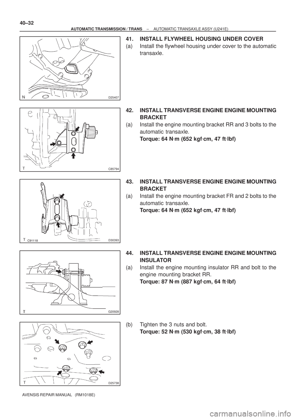
41. INSTALL FLYWHEEL HOUSING UNDER COVER
(a) Install the flywheel housing under cover to the automatic
transaxle.
42. INSTALL TRANSVERSE ENGINE ENGINE MOUNTING
BRACKET
(a) Install the engine mounting bracket RR and 3 bolts to the
automatic transaxle.
Torque: 64 N�m (652 kgf�cm, 47 ft�lbf)
43. INSTALL TRANSVERSE ENGINE ENGINE MOUNTING
BRACKET
(a) Install the engine mounting bracket FR and 2 bolts to the
automatic transaxle.
Torque: 64 N�m (652 kgf�cm, 47 ft�lbf)
44. INSTALL TRANSVERSE ENGINE ENGINE MOUNTING
INSULATOR
(a) Install the engine mounting insulator RR and bolt to the
engine mounting bracket RR.
Torque: 87 N�m (887 kgf�cm, 64 ft�lbf)
(b) Tighten the 3 nuts and bolt.
Torque: 52 N�m (530 kgf�cm, 38 ft�lbf)
Page 2701 of 5135

40±33
AVENSIS REPAIR MANUAL (RM1018E)
45. INSTALL TRANSVERSE ENGINE ENGINE MOUNTING
BR")
D30351
D30861
B
A
A
AA
C85797
C80168
A
A
BC
±
AUTOMATIC TRANSMISSION / TRANS AUTOMATIC TRANSAXLE ASSY (U241E)
40±33
AVENSIS REPAIR MANUAL (RM1018E)
45. INSTALL TRANSVERSE ENGINE ENGINE MOUNTING
BRACKET
(a) Install the engine mounting bracket LH and 3 bolts to the
automatic transaxle.
Torque: 64 N �m (653 kgf �cm, 47 ft �lbf)
46. INSTALL TRANSVERSE ENGINE ENGINE MOUNTING INSULATOR
(a) Install the engine mounting insulator LH, 5 bolts and nut. Torque:
Bolt A: 52 N �m (530 kgf �cm, 38 ft �lbf)
Nut B: 80 N �m (816 kgf �cm, 59 ft �lbf)
47. INSTALL TRANSVERSE ENGINE ENGINE MOUNTING INSULATOR
(a) Install the bolt and nut to the engine mounting bracket FR. Torque: 52 N �m (530 kgf �cm, 38 ft �lbf)
48. INSTALL ENGINE MOUNTING MEMBER SUB±ASSY CENTER
(a) Install the center member and 4 bolts. Torque:
Bolt A: 45 N �m (459 kgf �cm, 33 ft �lbf)
Bolt B: 96 N �m (979 kgf �cm, 71 ft �lbf)
Bolt C: 52 N �m (530 kgf �cm, 38 ft �lbf)
49. INSTALL STARTER ASSY
(a) Install the starter with the 2 bolts. Torque: 37 N �m (377 kgf �cm, 27 ft �lbf)
(b) Connect the connecter.
(c) Install the starter wire with the nut. Torque: 9.8 N �m (100 kgf �cm, 87 in. �lbf)
50.INSTALL FRONT DRIVE SHAFT ASSY LH (See page 30±6)
51.INSTALL FRONT DRIVE SHAFT ASSY RH (See page 30±6)
52.INSTALL EXHAUST PIPE ASSY FRONT (See page 15±7)
53. INSTALL FRONT WHEELS
Page 2703 of 5135

40±35
AVENSIS REPAIR MANUAL (RM1018E)
59. CONNECT CONNECTOR
(a) Connect the 2 clamps to the oil filler t")
D30342
D30341
BA
A
C81535
±
AUTOMATIC TRANSMISSION / TRANS AUTOMATIC TRANSAXLE ASSY (U241E)
40±35
AVENSIS REPAIR MANUAL (RM1018E)
59. CONNECT CONNECTOR
(a) Connect the 2 clamps to the oil filler tube.
(b) Connect the transmission wire connector.
(c) Connect the park/neutral position switch connector.
(d) Connect the 2 speed sensor connectors.
60. INSTALL WIRE HARNESS
(a) Install the 2 wire harnesses and wire harness bracket with
the 3 bolts.
Torque:
Bolt A: 5.0 N �m (51 kgf �cm, 44 in. �lbf)
Bolt B: 8.4 N �m (86 kgf �cm, 74 in. �lbf)
61. INSTALL TRANSMISSION CONTROL CABLE ASSY
(a) Temporarily install the control cable to the control shaft le- ver with nuts.
(b) Install the control cable and clip to the bracket.
62. INSTALL AIR CLEANER ASSY Torque: 5.0 N �m (50 kgf �cm, 44 in. �lbf)
63. INSTALL BATTERY CARRIER Torque: 13 N �m (132 kgf �cm, 10 ft �lbf)
64. INSTALL BATTERY
65. INSTALL ENGINE COVER SUB±ASSY NO.1 Torque: 9.0 N �m (92 kgf �cm, 80 in. �lbf)
66. INSTALL HOOD SUB±ASSY
Torque: 13 N �m (132 kgf �cm, 10 ft �lbf)
67.INSPECT HOOD SUB±ASSY (See page 75±2)
68.ADJUST HOOD SUB±ASSY (See page 75±2)
69. ADD COOLANT
(a)1AZ±FE (See pege 16±13)
(b)1AZ±FSE (See pege 16±25)
70. ADD AUTOMATIC TRANSAXLE FLUID
71.INSPECT AUTOMATIC TRANSAXLE FLUID (See page 40±2)
72.ADJUST SHIFT LEVER POSITION (See page 40±69)
73.INSPECT SHIFT LEVER POSITION (See page 40±69)
74.INSPECT AND ADJUST FRONT WHEEL ALIGNMENT (See page 26±6)
75. CHECK ABS SPEED SENSOR SIGNAL
Page 2706 of 5135
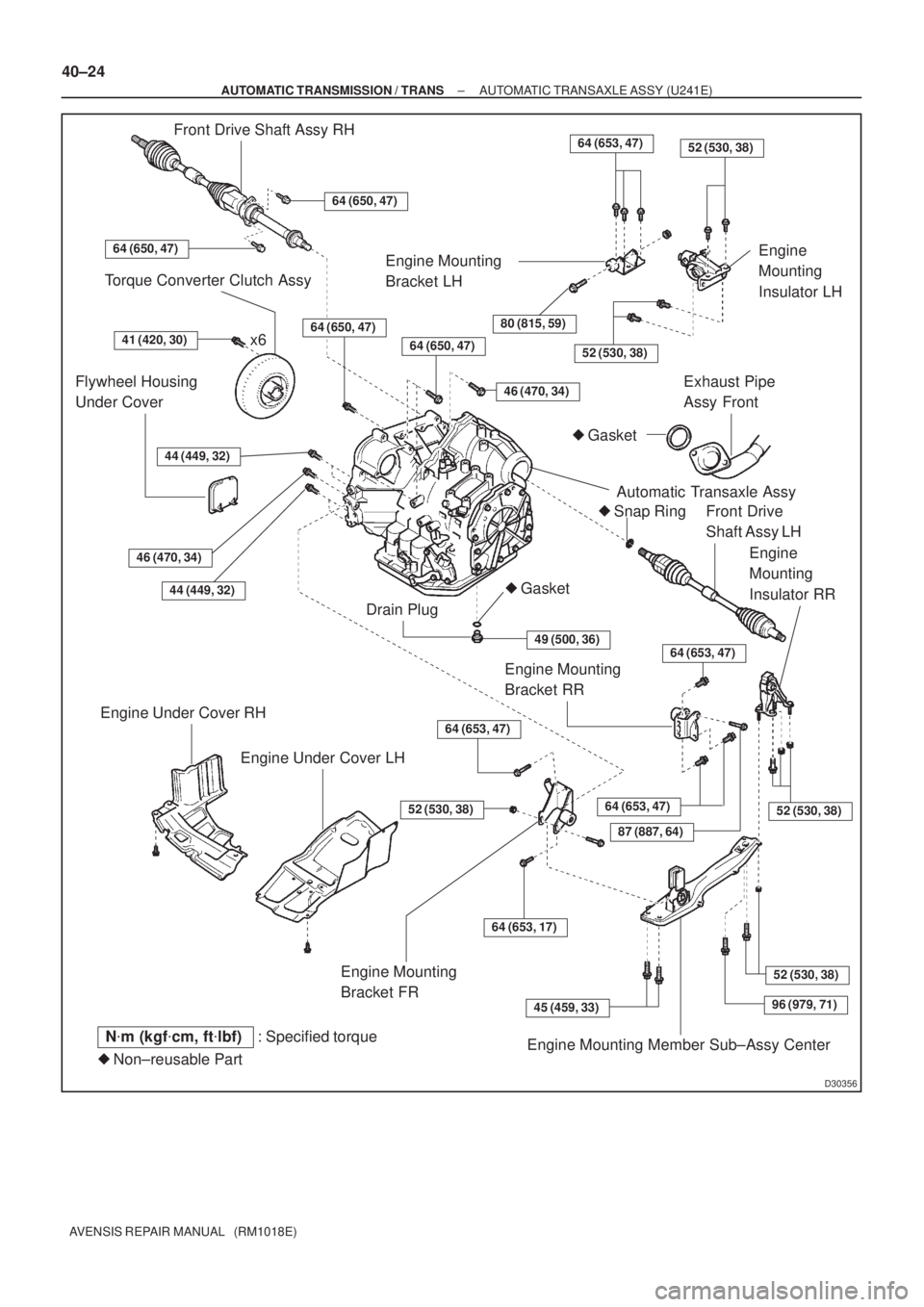
D30356
x6
�Gasket
�Non±reusable Part: Specified torque
Torque Converter Clutch Assy
41 (420, 30)
Flywheel Housing
Under Cover
44 (449, 32)
46 (470, 34)
44 (449, 32)
Engine Under Cover RH
Engine Under Cover LH
Engine Mounting
Bracket FR
52 (530, 38)
64 (653, 47)
64 (653, 17)
45 (459, 33)
Engine Mounting Member Sub±Assy Center
96 (979, 71)
52 (530, 38)
52 (530, 38)64 (653, 47)
87 (887, 64)
Engine Mounting
Bracket RR
64 (653, 47)
Engine
Mounting
Insulator RR
Front Drive
Shaft Assy LH
Automatic Transaxle Assy
�Snap Ring
Gasket
Exhaust Pipe
Assy Front
52 (530, 38)64 (650, 47)
80 (815, 59)
Engine
Mounting
Insulator LH
52 (530, 38)64 (653, 47)
Engine Mounting
Bracket LH
Drain Plug
N�m (kgf�cm, ft�lbf)
46 (470, 34)
49 (500, 36)
�
Front Drive Shaft Assy RH
64 (650, 47)
64 (650, 47)
64 (650, 47)
40±24
± AUTOMATIC TRANSMISSION / TRANSAUTOMATIC TRANSAXLE ASSY (U241E)
AVENSIS REPAIR MANUAL (RM1018E)
Page 2709 of 5135

40±13
AVENSIS REPAIR MANUAL (RM1018E)
18. REMOVE TRANSMISSION CONTROL CABLE
BRACKET NO.1
(a) Disconnect the w")
C91882
C94723
D25372
±
AUTOMATIC TRANSMISSION / TRANS AUTOMATIC TRANSAXLE ASSY (U341E)
40±13
AVENSIS REPAIR MANUAL (RM1018E)
18. REMOVE TRANSMISSION CONTROL CABLE
BRACKET NO.1
(a) Disconnect the wire harness clamp.
(b) Remove the 2 bolts and control cable bracket.
19. SEPARATE WIRE HARNESS
(a) Remove the bolt and wire harness.
20. SUSPEND ENGINE ASSY
(a) Install the No.1 and No.2 engine hangers in the correct
direction.
Parts No.:
No.1 engine hanger: 12281±22021
No.2 engine hanger: 12281±15040
Bolt: 91512±B1016
Torque: 38 N �m (387 kgf �cm, 28 ft �lbf)
(b) Attach the engine chain hoist to the engine hangers.
CAUTION:
Do not attempt to hang the engine by hooking the chain to
any other parts.
21. REMOVE FRONT WHEELS
22. DRAIN AUTOMATIC TRANSAXLE FLUID
(a) Remove the drain plug, gasket and drain ATF.
(b) Install a new gasket and the drain plug. Torque: 49 N �m (500 kgf �cm, 36 ft �lbf)
23.REMOVE EXHAUST PIPE ASSY FRONT (See page 15±2)
24.REMOVE FRONT DRIVE SHAFT ASSY LH (See page 30±6)
SST 09520±01010, 09520±24010 (09520±32040)
25.REMOVE FRONT DRIVE SHAFT ASSY RH (See page 30±6) SST 09520±01010, 09520±24010 (09520±32040)
26. REMOVE STARTER ASSY
(a) Remove the nut and disconnect the starter wire.
(b) Disconnect the connector.
(c) Remove the 2 bolts and starter.
27. SUPPORT AUTOMATIC TRANSAXLE ASSY
(a) Support the automatic transaxle with a transmission jack.
Page 2713 of 5135

40±17
AVENSIS REPAIR MANUAL (RM1018E)
(c) Using vernier calipers and a straight edg")
�
C65911
������D30888
A A
C
C B
B
C91990
D30348
± AUTOMATIC TRANSMISSION / TRANSAUTOMATIC TRANSAXLE ASSY (U341E)
40±17
AVENSIS REPAIR MANUAL (RM1018E)
(c) Using vernier calipers and a straight edge, measure the
dimension ºBº shown in the illustration and check that ºBº
is greater than ºAº measured in (b).
Standard: A + 1 mm or more
NOTICE:
Do not add the thickness of the straight edge.
40. INSTALL AUTOMATIC TRANSAXLE ASSY
(a) Install the automatic transaxle and 6 bolts to the engine.
Torque:
Bolt A: 64 N�m (650 kgf�cm, 47 ft�lbf)
Bolt B: 46 N�m (470 kgf�cm, 34 ft�lbf)
Bolt C: 23 N�m (235 kgf�cm, 17 ft�lbf)
(b) Install the 6 torque converter mounting bolts.
Torque: 28 N�m (285 kgf�cm, 20 ft�lbf)
HINT:
First install yellowish green colored bolt, and then the the 5
bolts.
41. INSTALL FLYWHEEL HOUSING UNDER COVER
(a) Install the flywheel housing under cover to the automatic transaxle.
42. INSTALL TRANSVERSE ENGINE ENGINE MOUNTING
BRACKET
(a) Install the engine mounting bracket RR and 3 bolts to the
automatic trasaxle.
Torque: 64 N�m (653 kgf�cm, 47 ft�lbf)

ADJUSTMENT
1. REMOVE REAR WHEEL
2.ADJUST PARKING BRAKE SHOE CLEARANCE (See page 33�")