Page 2534 of 5135
C68609
30±28
±
DRIVE SHAFT / PROPELLER SHAFT FRONT AXLE HUB SUB±ASSY LH
AVENSIS REPAIR MANUAL (RM1018E)
34. INSTALL FRONT AXLE HUB LH NUT
(a) While applying the brakes, install a new axle hub LH nut. Torque: 216 N �m (2,200 kgf �cm, 159 ft �lbf)
(b) Using a chisel and hammer, stake the axle hub LH nut.
35. INSTALL FRONT WHEEL Torque: 103 N �m (1,050 kgf �cm, 76 ft �lbf)
36.INSPECT AND ADJUST FRONT WHEEL ALIGNMENT (See page 26±6)
37. CHECK ABS SPEED SENSOR SIGNAL
(a)ABD WITH EBD SYSTEM (See page 05±699)
(b)ABD WITH EBD & BA & TRC & VSC SYSTEM ( See page 05±756)
Page 2536 of 5135

OVERHAUL
HINT:
Overhaul the RH side by the same procedures")
300JX±01
������F45751
SST
F13686
Hold
Turn
C80291
30±6
± DRIVE SHAFT / PROPELLER SHAFTFRONT DRIVE SHAFT
AVENSIS REPAIR MANUAL (RM1018E)
OVERHAUL
HINT:
Overhaul the RH side by the same procedures as the LH side.
1. DRAIN AUTOMATIC TRANSAXLE FLUID (A/T TRANSAXLE)
(a) Remove the drain plug and gasket, and then drain the ATF.
(b) Install a new gasket and drain plug.
Torque: 49 N�m (500 kgf�cm, 36 ft�lbf)
2. DRAIN MANUAL TRANSAXLE OIL (M/T TRANSAXLE)
(a) Remove the filler plug and gasket.
(b) Remove the drain plug and gasket.
(c) Install 2 new gaskets, drain plug and filler plug.
Torque:
C50/C250: 39 N�m (400 kgf�cm, 29 ft�lbf)
E354/E357: 49 N�m (500 kgf�cm, 36 ft�lbf)
3. REMOVE FRONT WHEEL
4. REMOVE ENGINE UNDER COVER LH
5. SEPARATE FRONT AXLE HUB LH NUT
(a) Using SST and a hammer, unstake the staked part of the
nut.
SST 09930±00010
(b) While applying the brakes, remove the axle hub LH nut.
NOTICE:
Loosen the staked part of the lock nut completely, other-
wise the screw of the drive shaft may be damaged.
6. SEPARATE FRONT STABILIZER LINK ASSY LH
(a) Remove the nut and separate the front stabilizer link assy
LH from the shock absorber assy LH.
HINT:
If the ball joint turns together with the nut, use a hexagon
wrench (6 mm) to hold the stud.
7. DISCONNECT SPEED SENSOR FRONT LH
(a) Remove the bolt, disconnect the speed sensor wire and
flexible hose from the shock absorber.
Page 2550 of 5135

48.INSTALL FRONT STABILIZER LINK ASSY LH
(a)Install the front stabilizer link assy LH")
F13686
HoldTurn
C68609
30±20
±
DRIVE SHAFT / PROPELLER SHAFT FRONT DRIVE SHAFT
AVENSIS REPAIR MANUAL (RM1018E)
48.INSTALL FRONT STABILIZER LINK ASSY LH
(a)Install the front stabilizer link assy LH with the nut. Torque: 74 N �m (755 kgf �cm, 55 ft �lbf)
HINT:
If the ball joint turns together with the nut, use a hexagon
wrench (6 mm) to hold the stud.
49.INSTALL FRONT AXLE HUB LH NUT
(a)Install a new axle hub LH nut. Torque: 216 N �m (2,200 kgf �cm, 159 ft �lbf)
(b)Using a chisel and hammer, stake the axle hub LH nut.
50.INSTALL ENGINE UNDER COVER LH
51.INSTALL FRONT WHEEL Torque: 103 N �m (1,050 kgf �cm, 76 ft �lbf)
52.ADD AUTOMATIC TRANSAXLE FLUID (A/T TRANSAXLE)
53.INSPECT AND ADJUST AUTOMATIC TRANSAXLE FLUID (A/T TRANSAXLE) (See page 40±2)
54. ADD MANUAL TRANSAXLE OIL (M/T TRANSAXLE)
55.INSPECT MANUAL TRANSAXLE OIL (M/T TRANSAXLE) (See page 41±2)
56.INSPECT AND ADJUST FRONT WHEEL ALIGNMENT (See page 26±6)
57. CHECK ABS SPEED SENSOR SIGNAL
(a)ABD WITH EBD SYSTEM (See page 05±699)
(b)ABD WITH EBD & BA & TRC & VSC SYSTEM ( See page 05±756)
Page 2559 of 5135
G23878
Inner side
Stopper Ring
G23876
G25774
27±30
±
REAR SUSPENSION STABILIZER BAR REAR
AVENSIS REPAIR MANUAL (RM1018E)
5. INSTALL STABILIZER BAR REAR
(a) Install the 2 stabilizer bush rear to each stabilizer bar rear.
HINT:
Install the stabilizer bush rear to the outer side of the stopper
ring on the stabilizer bar.
(b) Install the stabilizer bar rear and 2 rear stabilizer bar bracket No.3 with 2 bolts and 2 nuts.
Torque: 35 N �m (357 kgf �cm, 26 ft �lbf)
6. INSTALL REAR STABILIZER LINK ASSY LH
(a) Install the rear stabilizer link assy LH with the 2 nuts. Torque: 44 N �m (449 kgf �cm, 32 ft �lbf)
HINT:
If the ball joint turns together with the nut, use a hexagon (5 mm)
wrench to hold the stud.
7. INSTALL REAR STABILIZER LINK ASSY RH
HINT:
Install the RH side by the same procedures as the LH side.
8.INSPECT AND ADJUST REAR WHEEL ALIGNMENT (See page 27±4)
Page 2561 of 5135
G21542
G21542
G23879
Matchmarks
27±28
±
REAR SUSPENSION UPPER CONTROL ARM ASSY
AVENSIS REPAIR MANUAL (RM1018E)
(b) Install the upper control arm assy, and temporarily tighten the bolt and nut.
4. INSTALL REAR WHEEL Torque: 103 N �m (1,050 kgf �cm, 76 ft �lbf)
5.STABILIZE SUSPENSION (See page 27±8)
6. FULLY TIGHTEN UPPER CONTROL ARM ASSY
NOTICE:
Be sure to empty the vehicle when fully tightening the bolt
and nut.
(a) Fully tighten the bolt and nut.Torque: 74 N �m (755 kgf �cm, 55 ft �lbf)
NOTICE:
When instaling the bolt, hold the nut not to rotate.
(b) Align the matchmarks, and fully tighten the nut. Torque: 74 N �m (755 kgf �cm, 55 ft �lbf)
7.INSPECT AND ADJUST REAR WHEEL ALIGNMENT (See page 27±4)
Page 2563 of 5135

(e) Using SST, remove the lower control arm assy LH from
the rear axle")
������G23882
SST
G22395
G23871
������G25777
±
REAR SUSPENSION LOWER CONTROL ARM ASSY LH
27±25
AVENSIS REPAIR MANUAL (RM1018E)
(e) Using SST, remove the lower control arm assy LH from
the rear axle carrier sub±assy LH.
SST 09610±20012
NOTICE:
Do not damage the dust cover.
3. INSPECT LOWER CONTROL ARM ASSY LH
(a) Before installing the nut, flip the ball joint stud back and forth 5 times as shown in the illustration.
(b) Using a torque wrench, continuously turn the nut for 2 to 4 seconds per 1 turn, and take the torque reading at the
5th turn.
Turning torque:
3.0 N�m (31 kgf �cm, 27 in. �lbf) or less
NOTICE:
�Neither unusual drag nor rattle occurs during the
rotation.
�Neither crack nor grease leakage exists on the dust
cover.
�Make sure that lower control arm assy LH is not de-
formed.
4. INSTALL LOWER CONTROL ARM ASSY LH
(a) Install the member side lower control arm assy LH, and temporarily tighten bolt.
(b) Install the nut. Torque: 60 N �m (612 kgf �cm, 44 ft �lbf)
(c) Install the clip.
NOTICE:
�When the holes for the clip are not aligned, adjust
them by tightening the nut. The tightening angle for
the adjustment must be less than 60 �.
�Insert the clip from the rear side of a vehicle.
5. INSTALL REAR WHEEL Torque: 103 N �m (1,050 kgf �cm, 76 ft �lbf)
6.STABILIZE SUSPENSION (See page 27±8)
Page 2564 of 5135
G23871
G23906
27±26
±
REAR SUSPENSION LOWER CONTROL ARM ASSY LH
AVENSIS REPAIR MANUAL (RM1018E)
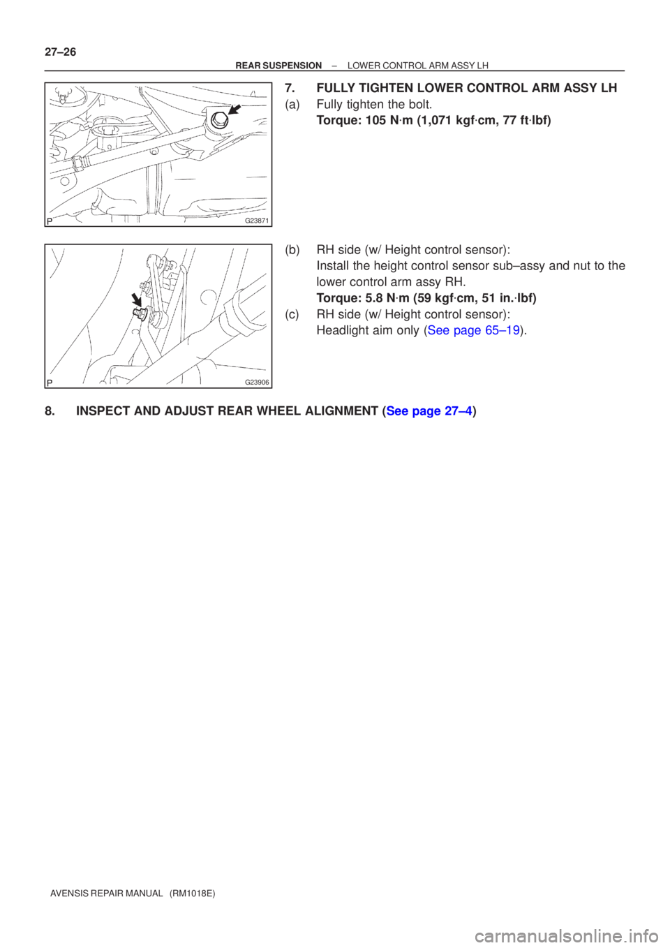
7. FULLY TIGHTEN LOWER CONTROL ARM ASSY LH
(a) Fully tighten the bolt. Torque: 105 N �m (1,071 kgf �cm, 77 ft �lbf)
(b) RH side (w/ Height control sensor): Install the height control sensor sub±assy and nut to the
lower control arm assy RH.
Torque: 5.8 N �m (59 kgf �cm, 51 in. �lbf)
(c) RH side (w/ Height control sensor): Headlight aim only (See page 65±19).
8.INSPECT AND ADJUST REAR WHEEL ALIGNMENT (See page 27±4)
Page 2572 of 5135
G23875
G23874
G23865
G23880
27±22
± REAR SUSPENSIONREAR SUSPENSION ARM ASSY NO.1 LH
AVENSIS REPAIR MANUAL (RM1018E)
14. INSTALL REAR WHEEL
Torque: 103 N�m (1,050 kgf�cm, 76 ft�lbf)
15. STABILIZE SUSPENSION
(a) Bounce the vehicle up and down several times to stabilize the suspension.
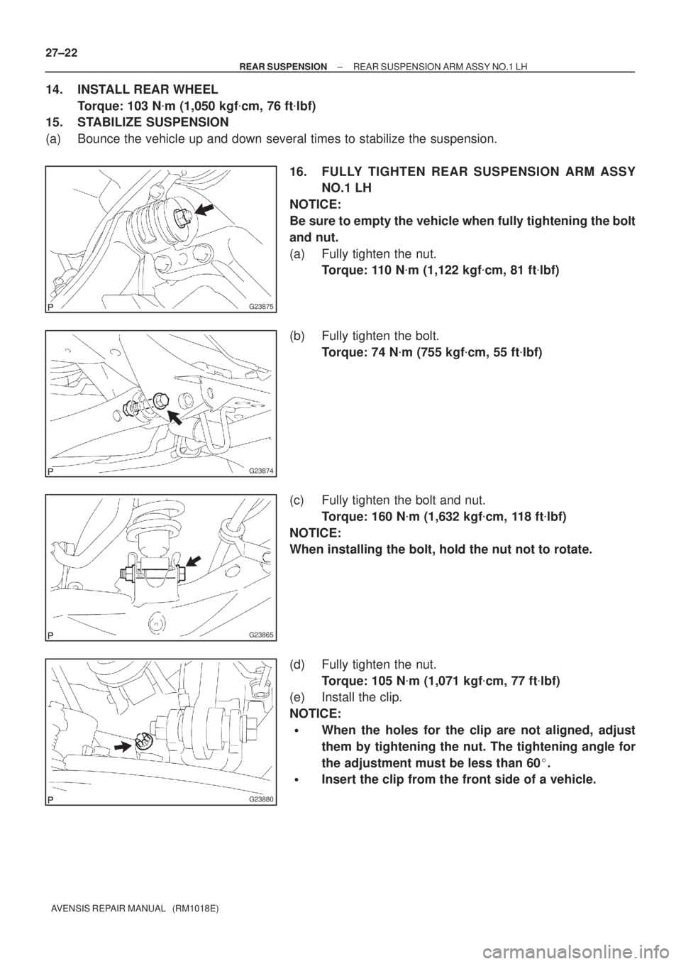
16. FULLY TIGHTEN REAR SUSPENSION ARM ASSY
NO.1 LH
NOTICE:
Be sure to empty the vehicle when fully tightening the bolt
and nut.
(a) Fully tighten the nut.
Torque: 110 N�m (1,122 kgf�cm, 81 ft�lbf)
(b) Fully tighten the bolt.
Torque: 74 N�m (755 kgf�cm, 55 ft�lbf)
(c) Fully tighten the bolt and nut.
Torque: 160 N�m (1,632 kgf�cm, 118 ft�lbf)
NOTICE:
When installing the bolt, hold the nut not to rotate.
(d) Fully tighten the nut.
Torque: 105 N�m (1,071 kgf�cm, 77 ft�lbf)
(e) Install the clip.
NOTICE:
�When the holes for the clip are not aligned, adjust
them by tightening the nut. The tightening angle for
the adjustment must be less than 60�.
�Insert the clip from the front side of a vehicle.

34. INSTALL FRONT AXLE HUB LH NUT
(a) While applying the brakes, install a new axle hub LH")

5. INSTALL STABILIZER BAR REAR
(a) Install the 2 stabilizer bush rear to ea")

(b) Install the upper control arm assy, and temporarily tighten the bolt and nut.
4.")