Page 2507 of 5135

LOWER BALL JOINT ASSY FRONT LH
REPLACEMENT
HINT:
�COMPONENTS: See page 26")
260DS±01
G22708
F40228
SST
ZX1712
26±24
±
FRONT SUSPENSION LOWER BALL JOINT ASSY FRONT LH
AVENSIS REPAIR MANUAL (RM1018E)
LOWER BALL JOINT ASSY FRONT LH
REPLACEMENT
HINT:
�COMPONENTS: See page 26±2
�Replace the RH side by the same procedures as the LH side. 1. INSPECT LOWER BALL JOINT ASSY FRONT LH
(a) Jack up front side of the vehicle.
(b) Check that there is no looseness on the ball joint by shak-ing the lower arm up and down with a force of 294 N (30
kgf, 66 lbf).
2. REMOVE FRONT WHEEL
3.SEPARATE FRONT AXLE HUB LH NUT (See page 30±6) SST 09930±00010
4.DISCONNECT SPEED SENSOR FRONT LH (See page 30±6)
5.SEPARATE FRONT DISC BRAKE CALIPER ASSY LH (See page 30±22)
6. REMOVE FRONT DISC
7.SEPARATE TIE ROD END SUB±ASSY LH (See page 30±22) SST 09628±62011
8.SEPARATE FRONT SUSPENSION ARM SUB±ASSY LOWER NO.1 LH (See page 30±22)
9.REMOVE FRONT AXLE ASSY LH (See page 30±22)
10. REMOVE LOWER BALL JOINT ASSY FRONT LH
(a) Remove the cotter pin and nut.
(b) Using SST, remove the lower ball joint assy front LH.
11. INSPECT LOWER BALL JOINT ASSY FRONT LH
(a) As shown in the illustration, flip the ball joint stud back andforth 5 times, before installing the nut.
(b) Using a torque wrench, turn the nut continuously at a rate of 3 ± 5 seconds per 1 turn and take the torque reading
on the 5th turn.
Turning torque:
0.98 ± 4.9 N´m (10 ± 50 kgf´cm, 9 ± 43 in.´lbf)
Page 2508 of 5135
±
FRONT SUSPENSION LOWER BALL JOINT ASSY FRONT LH
26±25
AVENSIS REPAIR MANUAL (RM1018E)
12. INSTALL LOWER BALL JOINT ASSY FRONT LH
(a) Install the lower ball joint assy front LH, and torque the nut.
Torque: 103 N �m (1,050 kgf �cm, 76 ft �lbf)
(b) Install a new cotter pin.
NOTICE:
If the holes for the cotter pin are not aligned, tighten the nut further\
up to 60 �.
13.INSTALL FRONT AXLE ASSY LH (See page 30±22)
14.INSTALL FRONT SUSPENSION ARM SUB±ASSY LOWER NO.1 LH (See page 30±22)
15.INSTALL TIE ROD END SUB±ASSY LH (See page 30±22)
16. INSTALL FRONT DISC
17.INSTALL FRONT DISC BRAKE CALIPER ASSY LH (See page 30±22)
18.CONNECT SPEED SENSOR FRONT LH (See page 30±6)
19.INSTALL FRONT AXLE HUB LH NUT (See page 30±6)
20. INSTALL FRONT WHEEL
Torque: 103 N �m (1,050 kgf �cm, 76 ft �lbf)
21.INSPECT AND ADJUST FRONT WHEEL ALIGNMENT (See page 26±6)
22. CHECK ABS SPEED SENSOR SIGNAL
(a)w/o VSC: See page 05±699
(b)w/ VSC: See page 05±756
Page 2510 of 5135

AVENSIS REPAIR MANUAL (RM1018E)
6. TEMPORARILY TIGHTEN FRONT SUSPENSION ARM
SUB±ASSY LOWER NO")
C80889
F41742
F13686
C80889
26±22± FRONT SUSPENSIONFRONT SUSPENSION ARM SUB±ASSY LOWER NO.1
LH (MTM)
AVENSIS REPAIR MANUAL (RM1018E)
6. TEMPORARILY TIGHTEN FRONT SUSPENSION ARM
SUB±ASSY LOWER NO.1 LH
(a) Install the lower suspension arm, temporary tighten the 2
bolts and nut.
7. CONNECT FRONT SUSPENSION ARM SUB±ASSY
LOWER NO.1 LH
(a) Connect the lower suspension arm to the lower ball joint
with the 2 nuts and bolt.
Torque: 89 N�m (908 kgf�cm, 66 ft�lbf)
8. CONNECT FRONT STABILIZER LINK ASSY LH
(a) Install the stabilizer bar link with the nut.
Torque: 74 N�m (755 kgf�cm, 55 ft�lbf)
HINT:
If the ball joint turns together with the nut, use a hexagon (6 mm)
wrench to hold the stud.
9. CONNECT FRONT STABILIZER LINK ASSY RH
HINT:
Install the RH side by the same procedures as the LH side.
10. STABILIZE SUSPENSION
(a) Install the front wheel and jack down the vehicle.
Torque: 103 N�m (1,050 kgf�cm, 76 ft�lbf)
(b) Bounce the vehicle up and down several times to stabilize the suspension.
11. FULLY TIGHTEN FRONT SUSPENSION ARM
SUB±ASSY LOWER NO.1 LH
(a) Fully tighten the 2 bolts and nut.
Torque: 137 N�m (1,400 kgf�cm, 101 ft�lbf)
Page 2515 of 5135
26±19
AVENSIS REPAIR MANUAL (RM1018E)
19. CONNECT FRONT SUSPENSION ARM SUB±ASSY
LOWER NO.1 LH
(a) Connect")
C80293
F13686
C80889
±
FRONT SUSPENSION FRONT SUSPENSION ARM SUB±ASSY LOWER NO.1
LH (ATM)26±19
AVENSIS REPAIR MANUAL (RM1018E)
19. CONNECT FRONT SUSPENSION ARM SUB±ASSY
LOWER NO.1 LH
(a) Connect the lower suspension arm to the lower ball joint
with the 2 nuts and bolt.
Torque: 89 N �m (908 kgf �cm, 66 ft �lbf)
20. CONNECT FRONT SUSPENSION ARM SUB±ASSY LOWER NO.1 RH
HINT:
Connect the RH side by the same procedures as the LH side.
21.INSTALL TIE ROD END SUB±ASSY LH (See page 30±6)
22. INSTALL TIE ROD END SUB±ASSY RH
HINT:
Connect the RH side by the same procedures as the LH side. 23. CONNECT FRONT STABILIZER LINK ASSY LH
(a) Install the stabilizer bar link with the nut.Torque: 74 N �m (755 kgf �cm, 55 ft �lbf)
HINT:
If the ball joint turns together with the nut, use a hexagon (6 mm)
wrench to hold the stud.
24. CONNECT FRONT STABILIZER LINK ASSY RH
HINT:
Install the RH side by the same procedures as the LH side.
25. STABILIZE SUSPENSION
(a) Install the front wheel and jack down the vehicle. Torque: 103 N �m (1,050 kgf �cm, 76 ft �lbf)
(b) Bounce the vehicle up and down several times to stabilize the suspension\
.
26. FULLY TIGHTEN FRONT SUSPENSION ARMSUB±ASSY LOWER NO.1 LH
(a) Fully tighten the 2 bolts and nut.
Torque: 137 N �m (1,400 kgf �cm, 101 ft �lbf)
Page 2522 of 5135
C80880
F13686
26±14
±
FRONT SUSPENSION FRONT SHOCK ABSORBER WITH COIL SPRING
AVENSIS REPAIR MANUAL (RM1018E)
(d) Install the flexible hose and ABS speed sensor wire har- ness bracket with the bolt.
Torque: 19 N �m (192 kgf �cm, 14 ft �lbf)
25. INSTALL FRONT STABILIZER LINK ASSY LH
(a) Install the stabilizer bar link with the nut. Torque: 74 N �m (755 kgf �cm, 55 ft �lbf)
HINT:
If the ball joint turns together with the nut, use a hexagon (6 mm)
wrench to hold the stud.
26. INSTALL FRONT WHEEL Torque: 103 N �m (1,050 kgf �cm, 76 ft �lbf)
27.INSPECT AND ADJUST FRONT WHEEL ALIGNMENT (See page 26±6)
Page 2523 of 5135

FRONT WHEEL ALIGNMENT
ADJUSTMENT
1.INSPECT TIRE")
2600L±02
F44617
Front:AB
F44618
Rear:
C D
SA3213
A
D B
Front
C
F44619
26±6
±
FRONT SUSPENSION FRONT WHEEL ALIGNMENT
AVENSIS REPAIR MANUAL (RM1018E)
FRONT WHEEL ALIGNMENT
ADJUSTMENT
1.INSPECT TIRE (See page 28±1) 2. MEASURE VEHICLE HEIGHT
Vehicle height:
(Normal package)
FrontA ± B: 92 mm (3.62 in.)
RearD ± C: 61 mm (2.40 in.)
(Rough road package)
FrontA ± B: 72 mm (2.83 in.)
RearD ± C: 41 mm (1.61 in.)
Measuring points:
A: Ground clearance of front wheel center
B: Ground clearance of lower suspension arm front bolt
center
C: Ground clearance of toe control arm inner bolt center
D: Ground clearance of rear wheel center
NOTICE:
Before inspecting the wheel alignment, adjust the vehicle
height to the specified value.
If the vehicle height is not the specified value, adjust it by push-
ing down or lifting the body.
3. INSPECT TOE±IN
Toe±in:
Toe±in(total)A + B: 0 �06' � 12' (0.1 � � 0.2 �)
C ± D: 1 � 2 mm (0.04 � 0.08 in.)
If the toe±in is not within the specified value, adjust it at the rack
ends.
4. ADJUST TOE±IN
(a) Remove the rack boot set clips.
(b) Loosen the tie rod end lock nuts.
(c) Turn the right and left rack ends by an equal amount to
adjust the toe±in.
HINT:
Adjust the toe±in to the center of the specified value as much
as possible.
(d) Make sure that the lengths of the right and left rack ends are the same.
(e) Torque the tie rod end lock nuts.
Torque: 74 N´m (755 kgf´cm, 55 ft´lbf)
(f) Place the boots on the seats and install the clips.
HINT:
Make sure that the boots are not twisted.
Page 2526 of 5135

F44962
+
±
F13685
1
2
F12938
Bolt
Adjusting
ValueSet BoltAdjusting Bolt90105±17008 90105±17009
90105±17010 90105±17011
121212121 Dot
2 Dots3 Dots
±1�30' ± ±1�15'
±1�15' ± ±1�00'
±1�00' ± ±45'
±45' ± ±30'
±30' ± ±15'
0' ± 15'
15' ± 30'
30' ± 45'
45' ± 1����
1�00' ± 1�15' ±15' ± 0'
1�15' ± 1�30'
± FRONT SUSPENSIONFRONT WHEEL ALIGNMENT
26±9
AVENSIS REPAIR MANUAL (RM1018E)
(e) Adjust the camber by pushing or pulling the lower side of
the shock absorber in the direction in which the camber
adjustment is required.
(f) Tighten the nuts.
Torque: 220 N�m (2,240 kgf�cm, 162 ft�lbf)
(g) Install the front wheel.
Torque: 103 N´m (1,050 kgf´cm, 76 ft´lbf)
(h) Check the camber.
HINT:
�Adjust the camber to the center of the specified value as
much as possible.
�Adjusting value for the set bolts is 6' ± 30' (0.1� ± 0.5�).
If the camber is not within the specified value, using the follow-
ing table, estimate how much additional camber adjustment will
be required, and select the camber adjusting bolt.
NOTICE:
Tighten the adjusting bolt with a washer and a new nut.
(i) Perform the procedure mentioned above again. At step
(b), replace 1 or 2 selected bolts.
HINT:
When replacing the 2 bolts, replace 1 bolt for each time.
Page 2527 of 5135
30092±02
D27405SST
Hold
Turn
D27401
Hold
Turn
Nut
Washer
±
DRIVE SHAFT / PROPELLER SHAFT FRONT AXLE LH HUB BOLT
30±29
AVENSIS REPAIR MANUAL (RM1018E)
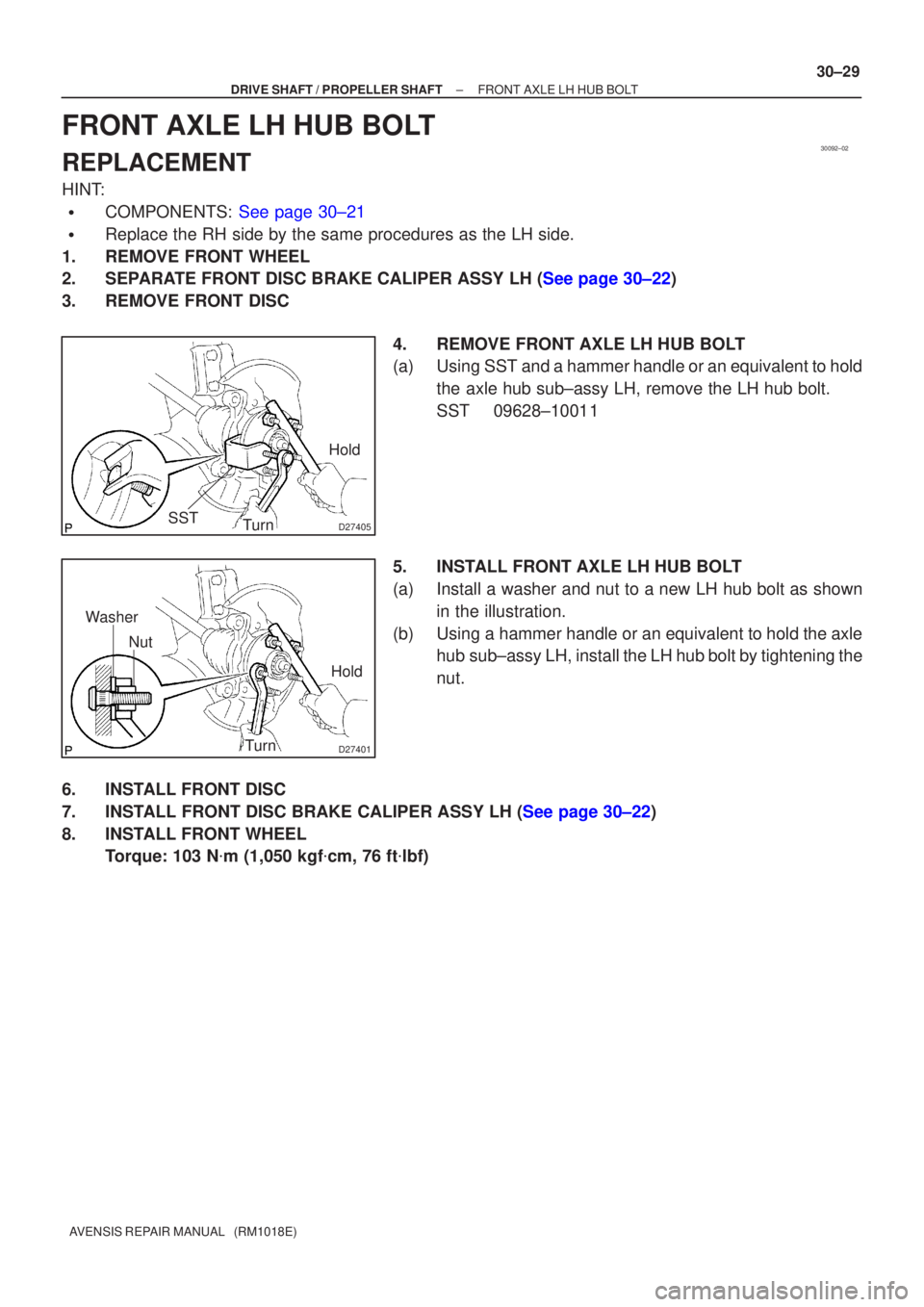
FRONT AXLE LH HUB BOLT
REPLACEMENT
HINT:
�COMPONENTS: See page 30±21
�Replace the RH side by the same procedures as the LH side.
1. REMOVE FRONT WHEEL
2.SEPARATE FRONT DISC BRAKE CALIPER ASSY LH (See page 30±22)
3. REMOVE FRONT DISC
4. REMOVE FRONT AXLE LH HUB BOLT
(a) Using SST and a hammer handle or an equivalent to holdthe axle hub sub±assy LH, remove the LH hub bolt.
SST 09628±10011
5. INSTALL FRONT AXLE LH HUB BOLT
(a) Install a washer and nut to a new LH hub bolt as shown in the illustration.
(b) Using a hammer handle or an equivalent to hold the axle hub sub±assy LH, install the LH hub bolt by tightening the
nut.
6. INSTALL FRONT DISC
7.INSTALL FRONT DISC BRAKE CALIPER ASSY LH (See page 30±22)
8. INSTALL FRONT WHEEL Torque: 103 N �m (1,050 kgf �cm, 76 ft �lbf)

12. INSTALL LOWER BALL JOINT ASSY FRONT LH
(a) Install the lower ball joint assy front LH, and torque the nu")

(d) Install the flexible hose and ABS speed sensor wire har- ness bracket with the bolt")