Page 2795 of 5135

41±21
AVENSIS REPAIR MANUAL (RM1018E)
51. INSTALL BATTERY CARRIER
(a) Install the battery carrier and 4 bolts.
Torque")
D30480
±
MANUAL TRANSMISSION/TRANSAXLE MANUAL TRANSAXLE ASSY (1ZZ±FE/3ZZ±FE)
41±21
AVENSIS REPAIR MANUAL (RM1018E)
51. INSTALL BATTERY CARRIER
(a) Install the battery carrier and 4 bolts.
Torque: 13 N �m (131 kgf �cm, 9 ft �lbf)
52. INSTALL BATTERY TRAY
53. INSTALL BATTERY
54. INSTALL BATTERY CLAMP SUB±ASSY Torque:
Bolt: 5.0 N �m (51 kgf �cm, 44 in. �lbf)
Nut: 3.5 N �m (36 kgf �cm, 31 in. �lbf)
55. INSTALL AIR CLEANER ASSY Torque: 5.0 N �m (51 kgf �cm, 44 in. �lbf)
56. INSTALL CYLINDER HEAD COVER NO.2 Torque: 7.0 N �m (71 kgf �cm, 62 in. �lbf)
57. INSTALL ENGINE ROOM COVER SIDE
58. INSTALL RADIATOR SUPPORT OPENING COVER
59. INSTALL HOOD SUB±ASSY Torque: 13 N �m (133 kgf �cm, 10 ft �lbf)
60.INSPECT HOOD SUB±ASSY (See page 75±2)
61.ADJUST HOOD SUB±ASSY (See page 75±2)
62.ADD TRANSAXLE OIL (See page 41±3)
63.INSPECT TRANSAXLE OIL (See page 41±2)
64. INSTALL FRONT WHEELS
Torque: 103 N �m (1,050 kgf �cm, 76 ft �lbf)
65.INSTALL STEERING INTERMEDIATE SHAFT (See page 50±9)
66.INSTALL STEERING COLUMN HOLE COVER SUB±ASSY NO.1 (See page 50±9)
67.INSTALL STEERING INTERMEDIATE SHAFT ASSY NO.2 (See page 50±9)
68.INSTALL COLUMN HOLE COVER SILENCER SHEET (See page 50±9)
69. PLACE FRONT WHEELS FACING STRAIGHT AHEAD
70. STEERING WHEEL CENTER POINT
71.INSPECT AND ADJUST FRONT WHEEL ALIGNMENT (See page 26±6)
72. INSTALL ENGINE UNDER COVER LH
73. INSTALL ENGINE UNDER COVER RH
74. CHECK ABS SPEED SENSOR SIGNAL
(a)w/ VSC (See page 05±756)
(b)w/o VSC (See page 05±699)
75.HEADLIGHT AIM ONLY (W/ DISCHARGE HEAD LAMP) (See page 65±19)
Page 2799 of 5135

Electronic Power Steering System:
SymptomSuspect AreaSee page
Hard steering
1. Tires (Improperly inflated)
2. Front whe")
±
POWER STEERING POWER STEERING SYSTEM
51±3
AVENSIS REPAIR MANUAL (RM1018E)
Electronic Power Steering System:
SymptomSuspect AreaSee page
Hard steering
1. Tires (Improperly inflated)
2. Front wheel alignment (Incorrect)
3. Steering system joints (Worn)
4. Suspension arm ball joints (Worn)
5. Steering column (Binding)
6. Steering column (Electric power steering system)
7. Steering gear (torque)28±1
26±6
±
26±24 ±
50±9
51±28
Poor return
1. Tires (Improperly inflated)
2. Front wheel alignment (Incorrect)
3. Steering column (Binding)
4. Steering column (Electric power steering system)
5. Steering gear (torque)28±1
26±6 ±
50±9
51±28
Excessive play
1. Steering system joints (Worn)
2. Suspension arm ball joints (Worn)
3. Intermediate shaft, Sliding yoke (Worn)
4. Front wheel bearing (Worn)
5. Steering column (Electric power steering system)
6. Steering gear (torque)±
26±24 ±
30±2
50±9
51±28
Abnormal noise
1. Steering system joints (Worn)
2. Steering column (Electric power steering system)
3. Steering gear (torque)±
50±9
51±28
HINT:
When the problem occurs on the Electric Power Steering system, refer to \
the DI section (See page 05±1042
).
Page 2814 of 5135

54.INSTALL INSTRUMENT PANEL AIR BAG ASSY (See page 60±54)
55. INSTALL COLUMN")
F44800
Marks
F44801
Torx ScrewScrew Case
±
STEERING COLUMN STEERING COLUMN ASSY
50±19
AVENSIS REPAIR MANUAL (RM1018E)
54.INSTALL INSTRUMENT PANEL AIR BAG ASSY (See page 60±54)
55. INSTALL COLUMN HOLE COVER SILENCER SHEET
56. PLACE FRONT WHEELS FACING STRAIGHT AHEAD
57.INSTALL SPIRAL CABLE SUB±ASSY (See page 60±26)
58. CENTER SPIRAL CABLE
(a) Check that the front wheels are facing straight ahead.
(b) Turn the cable counterclockwise by hand until it becomesharder to turn.
(c) Then rotate the cable clockwise about 2.5 turns to align the marks.
HINT:
The cable will rotate about 2.5 turns to either left or right of the
center.
59. INSTALL STEERING WHEEL ASSY
(a) Align matchmarks on the steering wheel and main shaft assembly.
(b) Install the steering wheel set nut. Torque: 50 N´m (510 kgf´cm, 37 ft´lbf)
(c) Connect the connector.
60. INSTALL HORN BUTTON ASSY
NOTICE:
�Never use airbag parts from another vehicle. When
replacing parts, replace with new ones.
�Make sure the horn button assy is installed with the
specified torque.
�If the horn button assy has been dropped, or there are
cracks, dents or other defects in the case or connec-
tor, replace the horn button assy with a new one.
�When installing the horn button assy, take care that
the wirings do not interfere with other parts and that
they are not pinched between other parts.
(a) Connect the terminal.
(b) Connect the airbag connector.
(c) Install the steering horn button assy after confirming that the circumference groove of the torx screws is caught on
the screw case.
(d) Using a torx socket wrench, torque the 2 screws. Torque: 8.8 N´m (90 kgf´cm, 78 in.´lbf)
61. STEERING WHEEL CENTER POINT
62. CONNECT BATTERY NEGATIVE TERMINAL
63.INSPECT SRS WARNING LIGHT(See page 05±1184)
64. PERFORM CALIBRATION OF TORQUE SENSOR ZERO POINT (ELECTRIC POWER STEERING) (See page 05±1045)
Page 2815 of 5135

5006X−01
Steering
Column
Protector No.1
F44781
Horn Button Assy
Steering Wheel Assy
Spiral Cable Sub −Assy
Steering Column Cover
Headlamp Dimmer Switch AssySteering Column Assy
Steering
Sliding Yoke
Sub− Assy
Steering Intermediate
Shaft Assy No.2
Column Hole Cover Silencer Sheet
Steering Column Cover LWR
Windshield Wiper
Switch Assy
N
�m (kgf �cm, ft�lbf): Specified torque
OIL Pressure Power Steering:
Steering Intermediate
Shaft Assy No.2
Steering
Sliding Yoke
Sub−Assy
35 (360, 26)
Column Hole Cover
Silencer Sheet
LHD Steering Position Type:
LHD Steering Position
Type: w/ Instrument Cluster
Finish Panel Assy
Floor Shift
Parking Lock Cable
Assy (A/T Transaxle)
Instrument Panel
Hole Cover
5 (51, 44 in.�
�� � lbf)
18 (184, 13)
18 (184, 13)
Instrument Panel
Airbag Assy
18 (184, 13)
18 (184, 13)
18 (184, 13)
25 (255, 18)
50 (510, 37)
35 (360, 26)
35 (360, 26)
28 (286, 21)
35 (360, 26)
28 (286, 21)
25 (255, 18)
25 (255, 18)
−
STEERING COLUMN STEERING COLUMN ASSY
50−5
STEERING COLUMN ASSY
COMPONENTS
Page 2817 of 5135
F44779
Horn Button Assy
Steering Wheel Assy
Headlamp Dimmer Switcn Assy
Spiral Cable
Windshield Wiper Switch Steering Column Cover
Steering Column Assy
Steering
Intermediate
Shaft Assy
No.2
Steering Sliding
Yoke sub−assy
Column Hole Cover Silencer Sheet
N �m (kgf �cm, ft�lbf): Specified torque Steering Sliding
Yoke sub
−assy
Steering Intermediate
Shaft Assy No.2
LHD Steering Position Type:
Electric Power Steering:
35 (360, 26)
35 (360, 26)
35 (360, 26)
Column Hole Cover Silencer Sheet
Steering Column Cover
LW R
Floor Shift Parking Lock
Cable Assy (A/T Transaxle)
Instrument Panel Airbag Assy
18 (184, 13)
Steering
Column
Protector
No.1
Instrument
Panel
Hole Cover
18 (184, 13)
18 (184, 13)
5 (51, 44 in. �
�� � lbf)
25 (255, 18)
18 (184, 13)
18 (184, 13)
LHD Steering Position Type: w/ Instrument Cluster
Finish Panel Assy
50 (510, 37)
25 (255, 18)
Steering Column
Protector No.1
35 (360, 26)
M/T Transaxle:25 (255, 18)
−
STEERING COLUMN STEERING COLUMN ASSY
50−7
Page 2822 of 5135

STEERING SYSTEM
PRECAUTION
1. HANDLING PRECAUTIONS ON STEERING SYSTEM
(a) Be careful to replace the parts properly")
5000C±14
±
STEERING COLUMN STEERING SYSTEM
50±1
AVENSIS REPAIR MANUAL (RM1018E)
STEERING SYSTEM
PRECAUTION
1. HANDLING PRECAUTIONS ON STEERING SYSTEM
(a) Be careful to replace the parts properly because they could affect the performance of the steering sys-
tem and result in a driving hazard.
2. HANDLING PRECAUTIONS ON SRS AIRBAG SYSTEM
(a) The vehicle is equipped with SRS (Supplemental Restraint System) such as \
the driver airbag and front passenger airbag. Failure to carry out service operation in the correct sequence \
could cause the SRS
to unexpectedly deploy during servicing, possibly leading to a serious acc\
ident. Before servicing (in-
cluding removal or installation of parts, inspection or replacement), be sure \
to read the precautionary
notices in the supplemental restraint system (See page 60±1).
3. HANDLING PRECAUTIONS ON STEERING COLUMN
(a) Do not give an impact to the steering column assy, especially the motor and the torque sensor. If a great impact is given (dropping it to the floor, etc.), replace it with a new one.
(b) When removing the steering column assy, do not pull the harness.
(c) When having replaced the steering column assy and/or the ECU, calibrate the \
zero point of the steer- ing torque sensor.
(d) In the case of disconnecting a connector related to the power steering sys\
tem, turn the ignition switch ON, set the steering wheel in the straight±ahead position and turn th\
e ignition switch OFF before dis-
connecting the connector.
(e) In the case of connecting a connector related to the power steering system, make sure that the ignit\
ion switch is OFF at first. After connecting the connector, set the steering wheel assy in the straight±ahead
position, and then turn the ignition switch ON.
NOTICE:
Never turn on the ignition switch when the steering wheel assy is set in orde\
r than the straight±ahead
position.
(f) If the above operation is not done, the zero point of the steering torque \
sensor is shifted away from the proper position, making difference in the steering effort between right and left. If this happens, per-
form the zero point calibration of the steering torque sensor (See page 05±1042).
Page 2825 of 5135

D26323
SST(s)
Matchmarks 7
1 (Temporally), 4
3
6
2.58
D00205
SST(s)
42±28
± CLUTCHCLUTCH UNIT (MTM)
AVENSIS REPAIR MANUAL (RM1018E)")
Q01060
D30059
1CD±FTV Engine Type: Others:
Flywheel Side
SST(s)
D26323
SST(s)
Matchmarks 7
1 (Temporally), 4
3
6
2.58
D00205
SST(s)
42±28
± CLUTCHCLUTCH UNIT (MTM)
AVENSIS REPAIR MANUAL (RM1018E)
12. INSPECT CLUTCH RELEASE BEARING ASSY
(a) Turn the release bearing by hand while applying force in
the axial direction.
HINT:
The bearing is permanently lubricated and requires no cleaning
or lubrication.
Replace the release bearing assy as necessary.
13. INSTALL CLUTCH DISC ASSY
(a) Insert SST(s) in the clutch disc assy, then insert them in
the flywheel sub±assy.
SST 09301±00220
NOTICE:
Take care not to insert the clutch disc assy in the wrong
direction.
14. INSTALL CLUTCH COVER ASSY
(a) Align matchmarks on the clutch cover assy and flywheel
sub±assy.
(b) Following the procedures shown in the illustration, tighten
the 6 bolts, in the order starting from the bolt located near
the knock pin on the top.
Torque: 19 N�m (195 kgf�cm, 14 ft�lbf)
HINT:
�Following the order in the illustration, tighten the bolts at
a time evenly.
�Move SST(s) up and down, right and left lightly, after
checking that the disc is in the center, and then tighten the
bolts.
15. INSPECT AND ADJUST CLUTCH COVER ASSY
(a) Using a dial indicator with roller instrument, check the dia-
phragm spring tip alignment.
Maximum non±alignment: 0.5 mm (0.020 in.)
If the alignment is not as specified, adjust the diaphragm spring
tip alignment using SST(s).
SST 09333±00013
Page 2827 of 5135
4206H±01
D26321
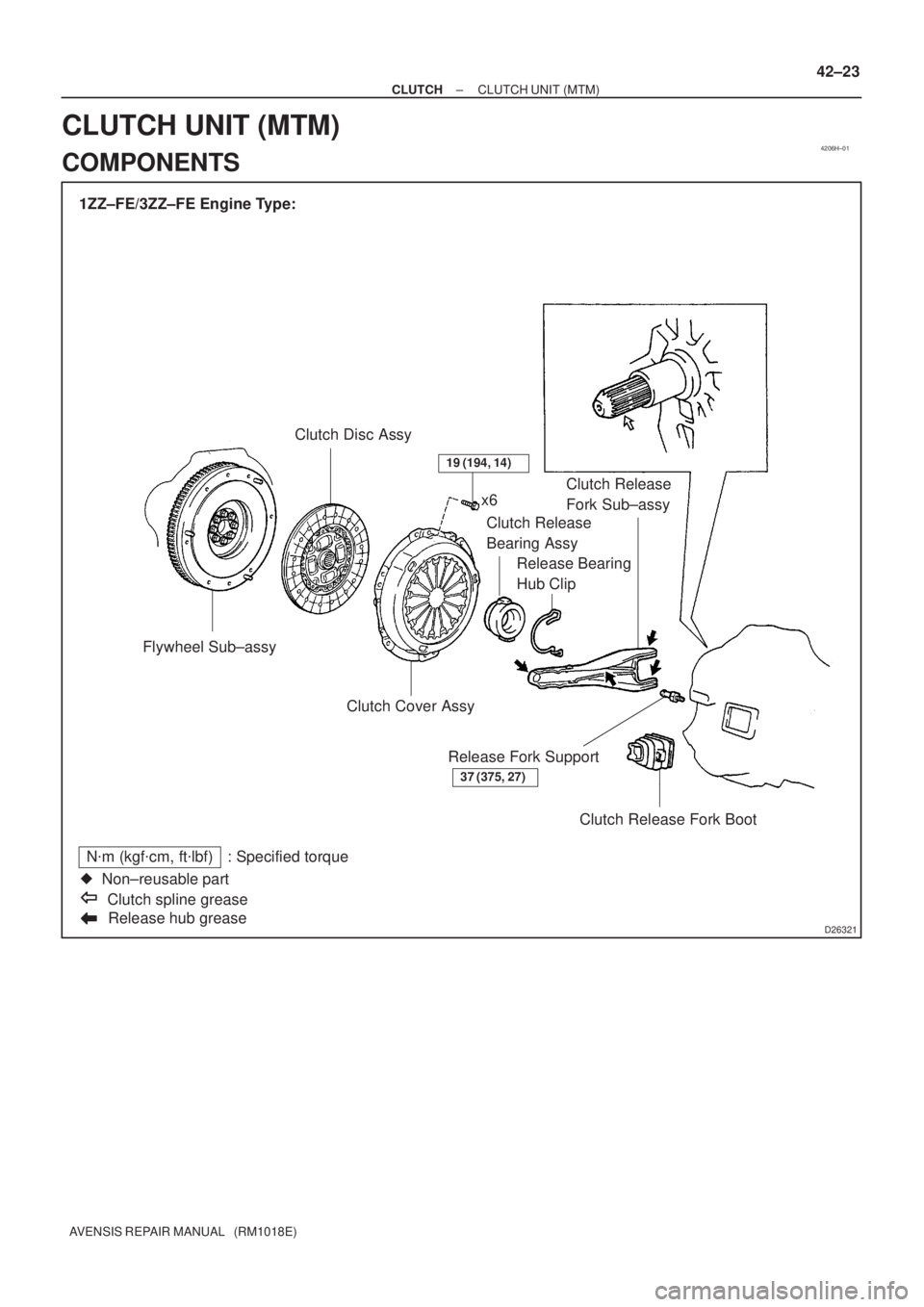
1ZZ±FE/3ZZ±FE Engine Type:
Flywheel Sub±assyClutch Disc Assy
Release hub grease
N�m (kgf�cm, ft�lbf) : Specified torque
�Non±reusable part
Clutch spline greasex6
Clutch Release
Bearing Assy
Release Bearing
Hub ClipClutch Release
Fork Sub±assy
Clutch Cover Assy
Clutch Release Fork Boot Release Fork Support
37 (375, 27)
19 (194, 14)
± CLUTCHCLUTCH UNIT (MTM)
42±23
AVENSIS REPAIR MANUAL (RM1018E)
CLUTCH UNIT (MTM)
COMPONENTS