Page 2981 of 5135
6009O±06
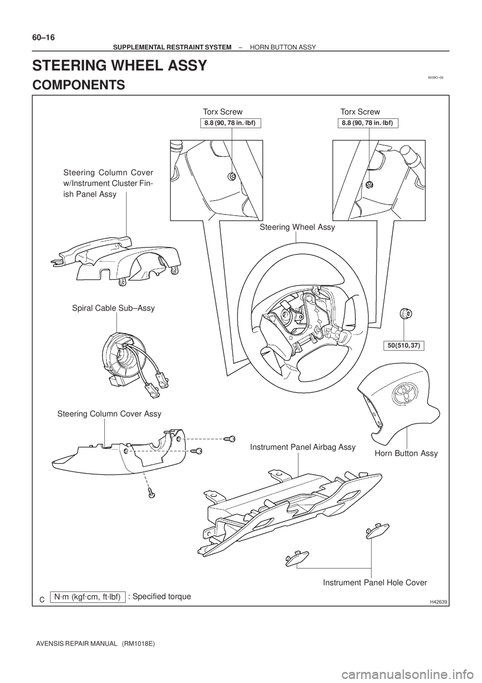
H42639N�m (kgf�cm, ft�lbf): Specified torqueTorx Screw
Steering Column Cover
w/Instrument Cluster Fin-
ish Panel Assy
Torx Screw
Horn Button Assy Steering Column Cover AssySpiral Cable Sub±Assy
Steering Wheel Assy
50 (510, 37)
Instrument Panel Airbag Assy
Instrument Panel Hole Cover
8.8 (90, 78 in.�lbf)8.8 (90, 78 in.�lbf)
60±16
± SUPPLEMENTAL RESTRAINT SYSTEMHORN BUTTON ASSY
AVENSIS REPAIR MANUAL (RM1018E)
STEERING WHEEL ASSY
COMPONENTS
Page 3233 of 5135
B66038
Heater to Register Duct No.2
Instrument Panel Lower Assy
Cowl Side Trim
Board RH
Front Door
Scuff Plate
RH
Floor Shift
Shift Lever
Knob Sub±assy Console Panel
Sub±assy Upper
Console Panel Sub±assy Lower
Console Box Assy RR Front Door
Scuff Plate LHCowl Side Trim
Board LH
Instrument Panel Airbag Assy
Console Rear End
Panel
Radio Receiver
Assembly w/ Bracket
Windshield
Wiper Switch Assy
Instrument Panel
Hole CoverHead lamp
Dimmer Switch Assy
Instrument Panel Under
Cover Sub±assy No.2
Horn Button Assy Steering Wheel Assy
Instrument Panel Under Cover
Sub±assy No.1
H
N´m (kgf´cm, ft´lbf) : Specified torqueM/T Transaxle: A/T Transaxle:
A/T Only:
M/T Only:
50 (510, 37)
8.8 (90, 78 in.´lbf)
orEF
D
B
Bor
EF
I
or
EF
or
EF
H
HH
H
H
HH
H
H
CC
CC
H
HConsole Panel
Sub±assy Upper
18 (184, 13)
18 (184, 13)
71±8
± INSTRUMENT PANEL/METERINSTRUMENT PANEL/METER
AVENSIS REPAIR MANUAL (RM1018E)
Page 3998 of 5135
![TOYOTA AVENSIS 2005 Service Repair Manual D25148
TA CDLC3 12345 768
9 1 0111 21 3 1 514 16
± DIAGNOSTICSELECTRONIC CONTROLLED AUTOMATIC
TRANSAXLE [ECT] (U341E)05±991
AVENSIS REPAIR MANUAL (RM1018E)
8. MECHANICAL SYSTEM TESTS
(a) Measure t](/manual-img/14/57441/w960_57441-3997.png "TOYOTA AVENSIS 2005 Service Repair Manual D25148
TA CDLC3 12345 768
9 1 0111 21 3 1 514 16
± DIAGNOSTICSELECTRONIC CONTROLLED AUTOMATIC
TRANSAXLE [ECT] (U341E)05±991
AVENSIS REPAIR MANUAL (RM1018E)
8. MECHANICAL SYSTEM TESTS
(a) Measure t")
D25148
TA CDLC3 12345 768
9 1 0111 21 3 1 514 16
± DIAGNOSTICSELECTRONIC CONTROLLED AUTOMATIC
TRANSAXLE [ECT] (U341E)05±991
AVENSIS REPAIR MANUAL (RM1018E)
8. MECHANICAL SYSTEM TESTS
(a) Measure the stall speed.
The object of this test is to check the overall performance of the transaxle and engine by measuring
the stall speeds in the D and R ranges.
NOTICE:
�Do the test at normal operating ATF temperature 50 to 80�C (122 to 176�F).
�Do not continuously run this test for longer than 5 seconds.
�To ensure safety, do this test in a wide, clear level area which provides good traction.
�The stall test should always be carried out in pairs. One technician should observe the condi-
tions of wheels or wheel stoppers outside the vehicle while the other is doing the test.
(1) Chock the 4 wheels.
(2) Connect the hand±held tester to DLC3 or tachome-
ter to terminal TAC of DLC3 with SST.
SST 09843±18030
(3) Fully apply the parking brake.
(4) Keep your left foot pressing firmly on the brake ped-
al.
(5) Start the engine.
(6) Shift into the D range. Press all the way down on the
accelerator pedal with your right foot.
(7) Quickly read the stall speed at this time.
Stall speed: 2,400 � 150 rpm
(8) Do the same test in the R range.
Stall speed: 2,400 � 150 rpm
Evaluation:
ProblemPossible cause
(a) Stall speed low in D and R ranges
�Engine output may be insufficient
�Stator one±way clutch not operating properly
HINT: If the value is larger or smaller than the specified value by
600 rpm or more, the torque converter could be faulty.
(b) Stall speed high in D range
�Line pressure too low
�Forward clutch slipping
�One±way clutch No.2 not operating properly
(c) Stall speed high in R range
�Line pressure too low
�Reverse clutch slipping
�1st and reverse brake slipping
(d) Stall speed high in D and R ranges�Line pressure too low
�Improper fluid level
Page 4036 of 5135
031H4−02
− SERVICE SPECIFICATIONSCOOLING
03−21
AVENSIS Supplement (RM1045E)
TORQUE SPECIFICATION
2AZ−FSE:
Part TightenedN�mkgf�cmft�lbf
Water pump x Cylinder block9.09280 in.�lbf
Water pump x Water pump pulley2626519
Water inlet x Cylinder block9.09280 in.�lbf
Radiator support upper x Body1919414
Fan assy w/ motor x Radiator6.06153 in.�lbf
Radiator relay block x Radiator5.05446 in.�lbf
1CD−FTV:
Part TightenedN�mkgf�cmft�lbf
Drain plug1313310
Water pump x Cylinder block3132023
Injection pipe x Common rail
With SST
Without SST
31
34316
34723
25
Injection pipe x Injector
For used pipe With SST
Without SST
For new pipe With SST
Without SST
36
40
31
34372
408
316
34727
30
23
25
Fuel inlet pipe sub−assy x Common rail assy
With SST
Without SST
31
34316
34723
25
Fuel inlet pipe sub−assy x Injection pump
With SST
Without SST
31
34316
34723
25
Timing belt idler Sub−assy No.1 x Cylinder head3535726
Front wheel1031,05076
Page 4040 of 5135

TORQUE SPECIFICATION
2AZ−FSE:
Part TightenedN�mkgf�cmft�lbf
Front wheel RH1031,05076
Drain plug (M/T)49500")
031H2−02
03−14
− SERVICE SPECIFICATIONSENGINE MECHANICAL
AVENSIS Supplement (RM1045E)
TORQUE SPECIFICATION
2AZ−FSE:
Part TightenedN�mkgf�cmft�lbf
Front wheel RH1031,05076
Drain plug (M/T)4950036
Engine hanger No.1 x Cylinder head3838728
Engine hanger No.2 x Cylinder head3838728
Engine coolant temperature sensor x Cylinder head2020815
Knock sensor x Cylinder block2020815
Engine oil pressure switch assy x Cylinder head1515311
Water by−pass pipe No.1 x Cylinder block9.09280 in.�lbf
Water by−pass pipe No. 3 x Cylinder block9.09280 in.�lbf
Oil cooler pipe x Cylinder block9.09280 in.�lbf
Drive shaft bearing bracket x Cylinder block5455140
Oil level gauge guide x Cylinder block9.09280 in.�lbf
V−ribbed belt tensioner assy x Timing chain cover6060744
Ignition coil assy x Cylinder head9.09280 in.�lbf
Water inlet x Cylinder block9.09280 in.�lbf
Exhaust manifold converter x Cylinder head3737827
Exhaust manifold stay x Exhaust manifold converter4444932
Exhaust manifold heat insulator No. 1 x Exhaust manifold converter121229
Surge tank stay No. 1 x Intake manifold2121015
Intake manifold x Cylinder head3030622
Throttle Body bracket x Throttle body2121015
Drive plate & ring gear x Crankshaft981,00072
Transverse engine engine mounting bracket front x Transverse engine en-
gine mounting insulator front8788764
Transverse engine engine mounting bracket rear x Transverse engine engine
mounting insulator rear8788764
Front suspension cross member sub−assy front x Body Bolt
Nut45
133459
1,35633
98
Front suspension brace RH x Frame Bolt A
Bolt B133
801,356
81698
59
Front suspension brace LH x Frame Bolt A
Bolt B133
801,356
81698
59
Transverse engine engine mounting insulator LH x Engine mounting bracket
LH8788764
Transverse engine engine mounting insulator RH x Engine mounting bracket
RH5253038
Engine mounting bracket x No. 2 RH x Transverse engine
engine mounting insulator A
B
52
11 3530
1,15238
83
Vane pump assy x Timing chain cover3737027
Front suspension arm sub−assy lower No. 1 x Lower ball joint1271,29694
Front stabilizer link assy x Front suspension7475555
Floor panel brace front x Floor3030622
Engine service cover bracket RH x Body RHD steering position type9.09280 in.�lbf
Cooler bracket x Body LHD steering position type9.09280 in.�lbf
Oil reservoir bracket No. 1 x Body8.08271 in.�lbf
Return tube sub−assy x Frame8.08271 in.�lbf
Radiator reserve tank Sub−assy x Body5.05144 in.�lbf
Compressor and magnetic clutch x Cylinder block2525518
Radiator relay block x Frame5.05144 in.�lbf
Page 4344 of 5135
![TOYOTA AVENSIS 2005 Service Repair Manual 05JL5−01
05−536− DIAGNOSTICSELECTRONIC CONTROLLED AUTOMATIC
TRANSAXLE [ECT] (U151E)
AVENSIS Supplement (RM1045E)
MECHANICAL SYSTEM TESTS
1. PERFORM MECHANICAL SYSTEM TESTS
(a) Measure the stall](/manual-img/14/57441/w960_57441-4343.png "TOYOTA AVENSIS 2005 Service Repair Manual 05JL5−01
05−536− DIAGNOSTICSELECTRONIC CONTROLLED AUTOMATIC
TRANSAXLE [ECT] (U151E)
AVENSIS Supplement (RM1045E)
MECHANICAL SYSTEM TESTS
1. PERFORM MECHANICAL SYSTEM TESTS
(a) Measure the stall")
05JL5−01
05−536− DIAGNOSTICSELECTRONIC CONTROLLED AUTOMATIC
TRANSAXLE [ECT] (U151E)
AVENSIS Supplement (RM1045E)
MECHANICAL SYSTEM TESTS
1. PERFORM MECHANICAL SYSTEM TESTS
(a) Measure the stall speed.
The object of this test is to check the overall performance of the transaxle and engine by measuring
the stall speeds in the D and R positions.
NOTICE:
SPerform the test at the normal operating ATF (Automatic Transmission Fluid) temperature 50
to 80˚C(122 to176˚F).
SDo not continuously run this test for longer than10 seconds.
STo ensure safety, do this test in a wide, clear level area which provides good traction.
SThe stall test should always be carried out in pairs. One technician should observe the condi-
tions of wheels or wheel stoppers outside the vehicle while the other is doing the test.
(1) Chock the 4 wheels.
(2) Connect an hand−held tester to the DLC3.
(3) Fully apply the parking brake.
(4) Keep your left foot pressed firmly on the brake pedal.
(5) Start the engine.
(6) Shift into the D position. Press all the way down on the accelerator pedal with your right foot.
(7) Quickly read the stall speed at this time.
Stall speed: 2,250�á150 rpm
(8) Do the same test in the R position.
Stall speed: 2,250�á150 rpm
Evaluation:
ProblemPossible cause
(a) Stall engine speed is low in D and R positions
SEngine power output may be insufficient
SStator one−way clutch not operating properly
HINT: If the value is less than the specified value by 600 rpm or
more, the torque converter could be faulty.
(b) Stall engine speed is high in D position
SLine pressure is too low
SForward clutch slipping
SU/D (Underdrive) brake slipping
SU/D (Underdrive) one−way clutch not operating properly
SNo.1one−way clutch not operating properly
(c) Stall engine speed is high in R position
SLine pressure is too low
SReverse clutch slipping
S1st and reverse brake slipping
SU/D (Underdrive) brake slipping
(d) Stall engine speed is high in D and R positionsSLine pressure is too low
SImproper fluid level
Page 4624 of 5135
(From
September, 2003)
AVENSIS Supplement (RM1045E)
122. SET NO. 1 CYLINDER TO TDC/COMPRESSION (See page 14 −138)
SST 09960 −10010 (")
14−176−
ENGINE MECHANICAL CYLINDER HEAD GASKET (1CD −FTV)(From
September, 2003)
AVENSIS Supplement (RM1045E)
122. SET NO. 1 CYLINDER TO TDC/COMPRESSION (See page 14 −138)
SST 09960 −10010 (09962 −01000, 09963 −01000)
123. INSTALL TIMING BELT (See page 14 −138)
124. CHECK VALVE TIMING (See page 14 −138)
125. INSTALL TIMING CHAIN COVER PLATE (See page 14 −138)
126. INSTALL TRANSVERSE ENGINE ENGINE MOUNTING BRACKET (See page 14 −138)
127. INSTALL TIMING BELT GUIDE (See page 14 −138)
128. INSTALL TIMING BELT NO.1 COVER (See page 14 −138)
129. INSTALL TIMING BELT NO.2 COVER (See page 14 −138)
130. INSTALL IDLER PULLEY SUB −ASSY (See page 14 −138)
131. INSTALL CRANKSHAFT PULLEY (See page 14 −138)
SST 09213 −54015 (09213 −70020), 09330 −00021
132. INSTALL ENGINE MOUNTING INSULATOR SUB −ASSY RH (See page 14 −138)
133. INSTALL POWER STEERING IDLE PULLEY BRACKET (See page 14 −108)
134. ADJUST V (COOLER COMPRESSOR TO CRANKSHAFT PULLEY) BELT NO.1
(See Pub. No. RM1018E on page 14 −269)
135. INSTALL INJECTOR DRIVER (See page 14 −108 )
136. INSTALL AIR TUBE NO.1 (See page 14 −108)
137. INSTALL AIR TUBE NO.2 (See page 14 −108)
138. INSTALL DIFFERENTIAL PRESSURE SENSOR ASSY (See page 14 −108)
139. INSTALL BATTERY (See page 14 −108)
140. INSTALL AIR CLEANER ASSY (See page 14 −108)
141. INSTALL VACUUM RESERVOIR SUB −ASSY (See page 14 −108)
142. INSTALL ENGINE COVER SUB −ASSY NO.1 (See page 14 −90)
143. INSTALL FRONT WHEEL RH Torque: 103 N �m (1,050 kgf �cm, 76 ft �lbf)
144. ADD ENGINE OIL (See Pub. No. RM1018E on page 17 −30)
145. ADD ENGINE COOLANT (See page 16 −19)
146. CHECK FOR FUEL LEAKS (See page 11 −46)
147. CHECK FOR ENGINE OIL LEAKS
148. CHECK FOR ENGINE COOLANT LEAKS (See page 16 −15)
149. CHECK FOR EXHAUST GAS LEAKS
Page 4633 of 5135
(From September, 2003)
14 −159
AVENSIS Supplement (RM1045E)
70. INSTALL TIMING BELT NO.1 COVER (See page 14 −138)
71. INSTALL TIMING BELT NO.2 COVER (See")
−
ENGINE MECHANICAL CAMSHAFT (1CD−FTV)(From September, 2003)
14 −159
AVENSIS Supplement (RM1045E)
70. INSTALL TIMING BELT NO.1 COVER (See page 14 −138)
71. INSTALL TIMING BELT NO.2 COVER (See page 14 −138)
72. INSTALL IDLER PULLEY SUB −ASSY (See page 14 −138)
73. INSTALL CRANKSHAFT PULLEY (See page 14 −138)
SST 09213 −54015 (09213 −70020), 09330 −00021
74. INSTALL ENGINE MOUNTING INSULATOR SUB −ASSY RH (See page 14 −138)
75. INSTALL POWER STEERING IDLE PULLEY BRACKET (See page 14 −108)
76. ADJUST V (COOLER COMPRESSOR TO CRANKSHAFT PULLEY) BELT NO.1
(See Pub. No. RM1018E on page 14 −269)
77. INSTALL INJECTOR DRIVER (See page 14 −108)
78. INSTALL AIR TUBE NO.1 (See page 14 −108)
79. INSTALL VACUUM RESERVOIR SUB −ASSY (See page 14 −108)
80. INSTALL BATTERY (See page 14 −108)
81. INSTALL AIR CLEANER ASSY (See page 14 −108)
82. INSTALL ENGINE COVER SUB −ASSY NO.1 (See page 14 −90)
83. INSTALL FRONT WHEEL RH Torque: 103 N �m (1,050 kgf �cm, 76 ft �lbf)
84. CHECK FOR FUEL LEAKS (See page 11 −46)