Page 2415 of 5135
170FU±01
A77281
17±8
±
LUBRICATION OIL PUMP ASSY(1AZ±FE)
AVENSIS REPAIR MANUAL (RM1018E)
OIL PUMP ASSY(1AZ±FE)
REPLACEMENT
1.DISCHARGE FUEL SYSTEM PRESSURE (See page 11±15)
2.REMOVE FRONT WHEEL RH
3.REMOVE RADIATOR SUPPORT OPENING COVER
4.REMOVE ENGINE ROOM COVER SIDE
5.REMOVE ENGINE UNDER COVER RH
6.REMOVE ENGINE UNDER COVER LH
7.DRAIN ENGINE OIL
(a)Install a new gasket and drain plug after draining engine oil. Torque: 25 N �m (250 kgf �cm,18 ft �lbf)
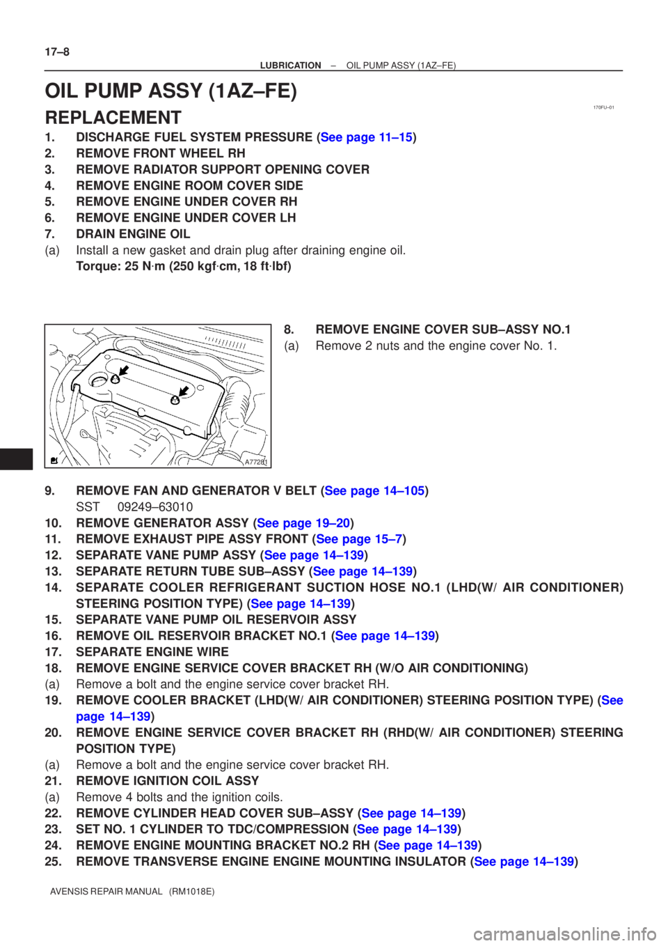
8.REMOVE ENGINE COVER SUB±ASSY NO.1
(a)Remove 2 nuts and the engine cover No. 1.
9.REMOVE FAN AND GENERATOR V BELT (See page 14±105) SST 09249±63010
10.REMOVE GENERATOR ASSY (See page 19±20)
11.REMOVE EXHAUST PIPE ASSY FRONT (See page 15±7)
12.SEPARATE VANE PUMP ASSY (See page 14±139)
13.SEPARATE RETURN TUBE SUB±ASSY (See page 14±139)
14. SEPARATE COOLER REFRIGERANT SUCTION HOSE NO.1 (LHD(W/ AIR CONDITIONER) STEERING POSITION TYPE) (See page 14±139)
15. SEPARATE VANE PUMP OIL RESERVOIR ASSY
16.REMOVE OIL RESERVOIR BRACKET NO.1 (See page 14±139)
17. SEPARATE ENGINE WIRE
18. REMOVE ENGINE SERVICE COVER BRACKET RH (W/O AIR CONDITIONING)
(a) Remove a bolt and the engine service cover bracket RH.
19.REMOVE COOLER BRACKET (LHD(W/ AIR CONDITIONER) STEERING POSITION TYPE\
) (See
page 14±139)
20. REMOVE ENGINE SERVICE COVER BRACKET RH (RHD(W/ AIR CONDITIONER) STEERING POSITION TYPE)
(a) Remove a bolt and the engine service cover bracket RH.
21. REMOVE IGNITION COIL ASSY
(a) Remove 4 bolts and the ignition coils.
22.REMOVE CYLINDER HEAD COVER SUB±ASSY (See page 14±139)
23.SET NO. 1 CYLINDER TO TDC/COMPRESSION (See page 14±139)
24.REMOVE ENGINE MOUNTING BRACKET NO.2 RH (See page 14±139)
25.REMOVE TRANSVERSE ENGINE ENGINE MOUNTING INSULATOR (See page 14±139)
Page 2419 of 5135
1700F±09
A56466
Recommended Viscosity (SAE)
BEFORE NEXT OIL CHANGE TEMPERATURE RANGE ANTICiPATED416 2738
0 20 40 60 80 100 ±29
±20±18 ±7 �C
�F20 W ± 50
15 W ± 40
10 W ± 30
5 W ± 30 PREFERRED
Oil Pressure Switch
B11410
Oil Pressure Switch
Oil Pressure Gauge
B11411
Oil Pressure Gauge 17±6
± LUBRICATIONLUBRICATION SYSTEM (1AZ±FE)
AVENSIS REPAIR MANUAL (RM1018E)
LUBRICATION SYSTEM (1AZ±FE)
ON±VEHICLE INSPECTION
1. CHECK ENGINE OIL LEVEL
(a) After warm up the engine and then 5 minutes after the engine stop, oil level should be between the
low level and full level marks of the dipstick.
If low, check for leakage and add oil up to the full level mark.
NOTICE:
Do not fill with engine oil above the full level mark.
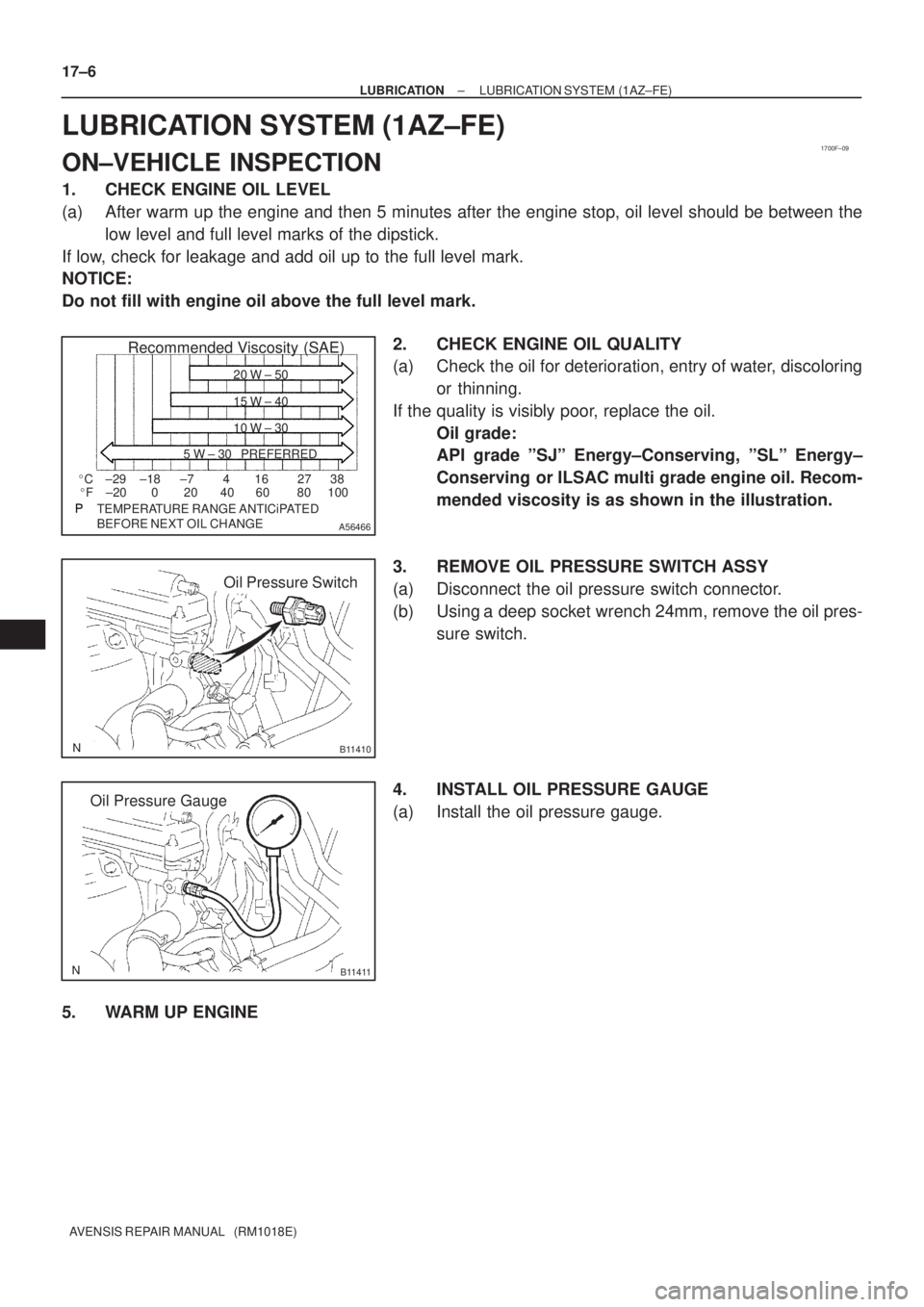
2. CHECK ENGINE OIL QUALITY
(a) Check the oil for deterioration, entry of water, discoloring
or thinning.
If the quality is visibly poor, replace the oil.
Oil grade:
API grade ºSJº Energy±Conserving, ºSLº Energy±
Conserving or ILSAC multi grade engine oil. Recom-
mended viscosity is as shown in the illustration.
3. REMOVE OIL PRESSURE SWITCH ASSY
(a) Disconnect the oil pressure switch connector.
(b) Using a deep socket wrench 24mm, remove the oil pres-
sure switch.
4. INSTALL OIL PRESSURE GAUGE
(a) Install the oil pressure gauge.
5. WARM UP ENGINE
Page 2420 of 5135
Adhesive
A50082
± LUBRICATIONLUBRICATION SYSTEM (1AZ±FE)
17±7
AVENSIS REPAIR MANUAL (RM1018E)
6. CHECK OIL PRESSURE
Oil pressure:
At idle29 kPa (0.3 kgf/cm2, 4.3 psi) or more
At 3,000 rpm245 to 539 kPa (2.5 to 5.5 kgf/cm2, 36 to 78 psi) or more
7. REMOVE OIL PRESSURE GAUGE
8. INSTALL OIL PRESSURE SWITCH ASSY
(a) Apply adhesive to 2 or 3 threads of the oil pressure switch.
Adhesive:
Part No. 08833±00080, THREE BOND 1344,
LOCTITE 242 or equivalent
(b) Using a deep socket wrench 24mm, install the oil pres-
sure switch.
Torque: 15 N�m (153 kgf�cm, 11 ft�lbf)
NOTICE:
Do not start the engine within 1 hour after the installation.
(c) Connect the oil pressure switch connector.
9. START ENGINE AND CHECK FOR LEAKS
Page 2424 of 5135
1700F±10
A56466
Recommended Viscosity (SAE)
BEFORE NEXT OIL CHANGE TEMPERATURE RANGE ANTICiPATED416 2738
0 20 40 60 80 100 ±29
±20±18 ±7 �C
�F20 W ± 50
15 W ± 40
10 W ± 30
5 W ± 30 PREFERRED
Oil Pressure
Switch
A80004
Oil Pressure GaugeOil Pressure Gauge
A50711
± LUBRICATIONLUBRICATION SYSTEM (1ZZ±FE/3ZZ±FE)
17±1
AVENSIS REPAIR MANUAL (RM1018E)
LUBRICATION SYSTEM (1ZZ±FE/3ZZ±FE)
ON±VEHICLE INSPECTION
1. CHECK ENGINE OIL LEVEL
(a) After warm up the engine and then 5 minutes after the engine stop, oil level should be between the
low level and full level marks of the dipstick.
If low, check for leakage and add oil up to the full level mark.
NOTICE:
Do not fill with engine oil above the full level mark.
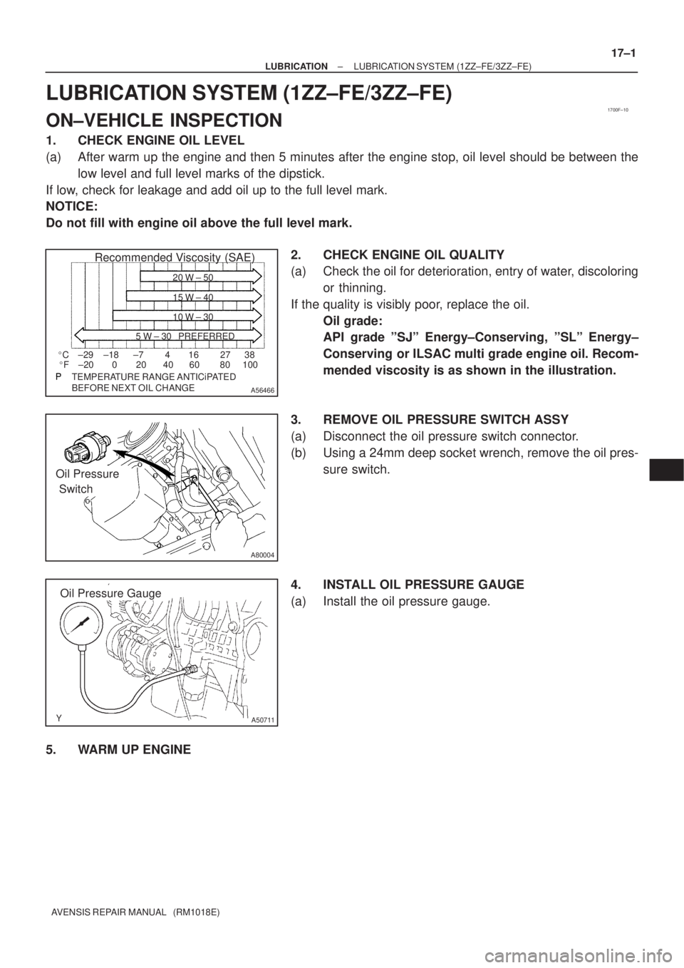
2. CHECK ENGINE OIL QUALITY
(a) Check the oil for deterioration, entry of water, discoloring
or thinning.
If the quality is visibly poor, replace the oil.
Oil grade:
API grade ºSJº Energy±Conserving, ºSLº Energy±
Conserving or ILSAC multi grade engine oil. Recom-
mended viscosity is as shown in the illustration.
3. REMOVE OIL PRESSURE SWITCH ASSY
(a) Disconnect the oil pressure switch connector.
(b) Using a 24mm deep socket wrench, remove the oil pres-
sure switch.
4. INSTALL OIL PRESSURE GAUGE
(a) Install the oil pressure gauge.
5. WARM UP ENGINE
Page 2425 of 5135
Adhesive
A50082
17±2
± LUBRICATIONLUBRICATION SYSTEM (1ZZ±FE/3ZZ±FE)
AVENSIS REPAIR MANUAL (RM1018E)
6. CHECK OIL PRESSURE
Oil pressure:
At idle29 kPa (0.3 kgf/cm2, 4.3 psi) or more
At 3,000 rpm294 to 539 kPa (3.0 to 5.5 kgf/cm2, 43 to 78 psi) or more
7. REMOVE OIL PRESSURE GAUGE
8. INSTALL OIL PRESSURE SWITCH ASSY
(a) Apply adhesive to 2 or 3 threads of the oil pressure switch.
Adhesive:
Part No. 08833±00080, THREE BOND 1344,
LOCTITE 242 or equivalent
(b) Using a 24mm deep socket wrench, install the oil pres-
sure switch.
Torque: 15 N�m (153 kgf�cm, 11 ft�lbf)
NOTICE:
Do not start the engine within 1 hour of installation.
(c) Connect the oil pressure switch connector.
9. START ENGINE AND CHECK FOR LEAKS
Page 2442 of 5135
A78640
1.0 to 1.1 mm
B62019
± IGNITIONIGNITION SYSTEM (1AZ±FSE)
18±15
AVENSIS REPAIR MANUAL (RM1018E)
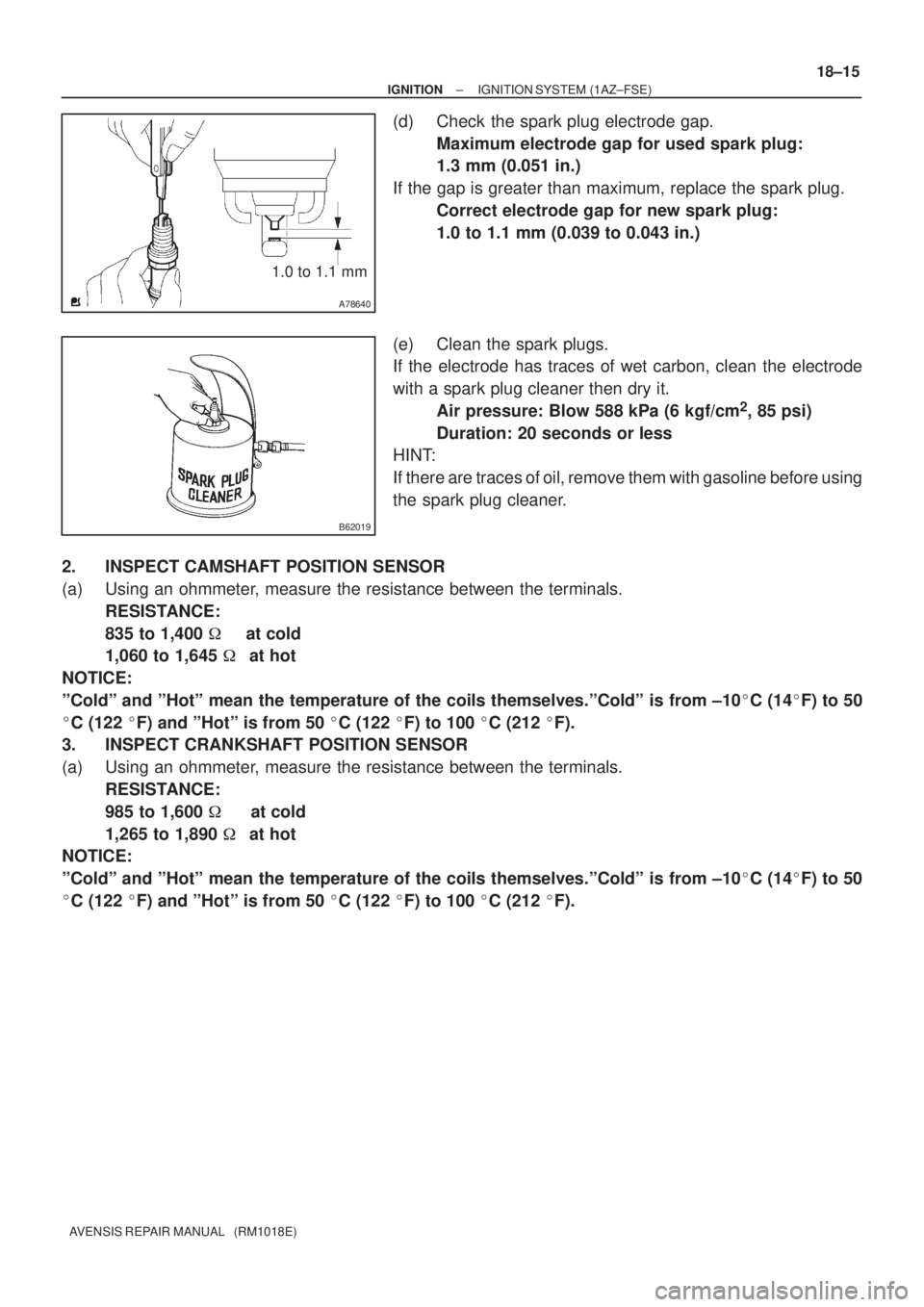
(d) Check the spark plug electrode gap.
Maximum electrode gap for used spark plug:
1.3 mm (0.051 in.)
If the gap is greater than maximum, replace the spark plug.
Correct electrode gap for new spark plug:
1.0 to 1.1 mm (0.039 to 0.043 in.)
(e) Clean the spark plugs.
If the electrode has traces of wet carbon, clean the electrode
with a spark plug cleaner then dry it.
Air pressure: Blow 588 kPa (6 kgf/cm
2, 85 psi)
Duration: 20 seconds or less
HINT:
If there are traces of oil, remove them with gasoline before using
the spark plug cleaner.
2. INSPECT CAMSHAFT POSITION SENSOR
(a) Using an ohmmeter, measure the resistance between the terminals.
RESISTANCE:
835 to 1,400 � at cold
1,060 to 1,645 �at hot
NOTICE:
ºColdº and ºHotº mean the temperature of the coils themselves.ºColdº is from ±10�C (14�F) to 50
�C (122 �F) and ºHotº is from 50 �C (122 �F) to 100 �C (212 �F).
3. INSPECT CRANKSHAFT POSITION SENSOR
(a) Using an ohmmeter, measure the resistance between the terminals.
RESISTANCE:
985 to 1,600 � at cold
1,265 to 1,890 �at hot
NOTICE:
ºColdº and ºHotº mean the temperature of the coils themselves.ºColdº is from ±10�C (14�F) to 50
�C (122 �F) and ºHotº is from 50 �C (122 �F) to 100 �C (212 �F).
Page 2446 of 5135
B01301
IG0316
B02101
1.1 mm
B62019
18±10
± IGNITIONIGNITION SYSTEM (1AZ±FE)
AVENSIS REPAIR MANUAL (RM1018E)
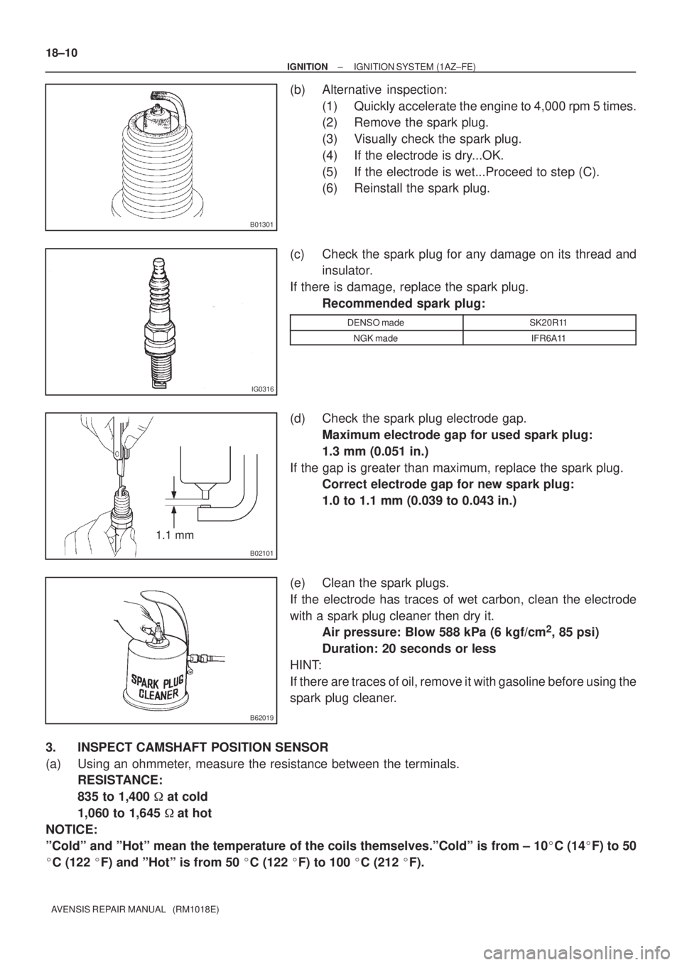
(b) Alternative inspection:
(1) Quickly accelerate the engine to 4,000 rpm 5 times.
(2) Remove the spark plug.
(3) Visually check the spark plug.
(4) If the electrode is dry...OK.
(5) If the electrode is wet...Proceed to step (C).
(6) Reinstall the spark plug.
(c) Check the spark plug for any damage on its thread and
insulator.
If there is damage, replace the spark plug.
Recommended spark plug:
DENSO madeSK20R11
NGK madeIFR6A11
(d) Check the spark plug electrode gap.
Maximum electrode gap for used spark plug:
1.3 mm (0.051 in.)
If the gap is greater than maximum, replace the spark plug.
Correct electrode gap for new spark plug:
1.0 to 1.1 mm (0.039 to 0.043 in.)
(e) Clean the spark plugs.
If the electrode has traces of wet carbon, clean the electrode
with a spark plug cleaner then dry it.
Air pressure: Blow 588 kPa (6 kgf/cm
2, 85 psi)
Duration: 20 seconds or less
HINT:
If there are traces of oil, remove it with gasoline before using the
spark plug cleaner.
3. INSPECT CAMSHAFT POSITION SENSOR
(a) Using an ohmmeter, measure the resistance between the terminals.
RESISTANCE:
835 to 1,400 � at cold
1,060 to 1,645 �at hot
NOTICE:
ºColdº and ºHotº mean the temperature of the coils themselves.ºColdº is from ± 10�C (14�F) to 50
�C (122 �F) and ºHotº is from 50 �C (122 �F) to 100 �C (212 �F).
Page 2452 of 5135
1807P±01
A50033
P03783
P03792
± IGNITIONIGNITION SYSTEM (1ZZ±FE/3ZZ±FE)
18±3
AVENSIS REPAIR MANUAL (RM1018E)
INSPECTION
1. INSPECT SPARK PLUG
(a) Clean the spark plugs.
If the electrode has traces of wet carbon, clean the electrode
with a spark plug cleaner then dry it.
Air pressure: Below 588 kPa (6kg/cm
2, 85 psi)
Duration: 20 seconds or less
(b) Check the spark plug for any damage on its thread and
insulator damage.
If there is damage, replace the spark plug.
Recommended spark plug:
DENSO madeK16R±U11
NGK madeBKR5EYA11
(c) Adjust electrode gap.
Electrode gap: 1.0 to 1.1 mm (0.039 to 0.043 in.)
2. INSPECT CAMSHAFT POSITION SENSOR
(a) Using an ohmmeter, measure the resistance between the terminals.
RESISTANCE:
835 to 1,400 � at cold
1,060 to 1,645 �at hot
NOTICE:
ºColdº and ºHotº mean the temperature of the coils themselves.ºColdº is from ± 10�C (14�F) to 50
�C (122 �F) and ºHotº is from 50 �C (122 �F) to 100 �C (212 �F).