Page 2379 of 5135
160N6±01
A78434
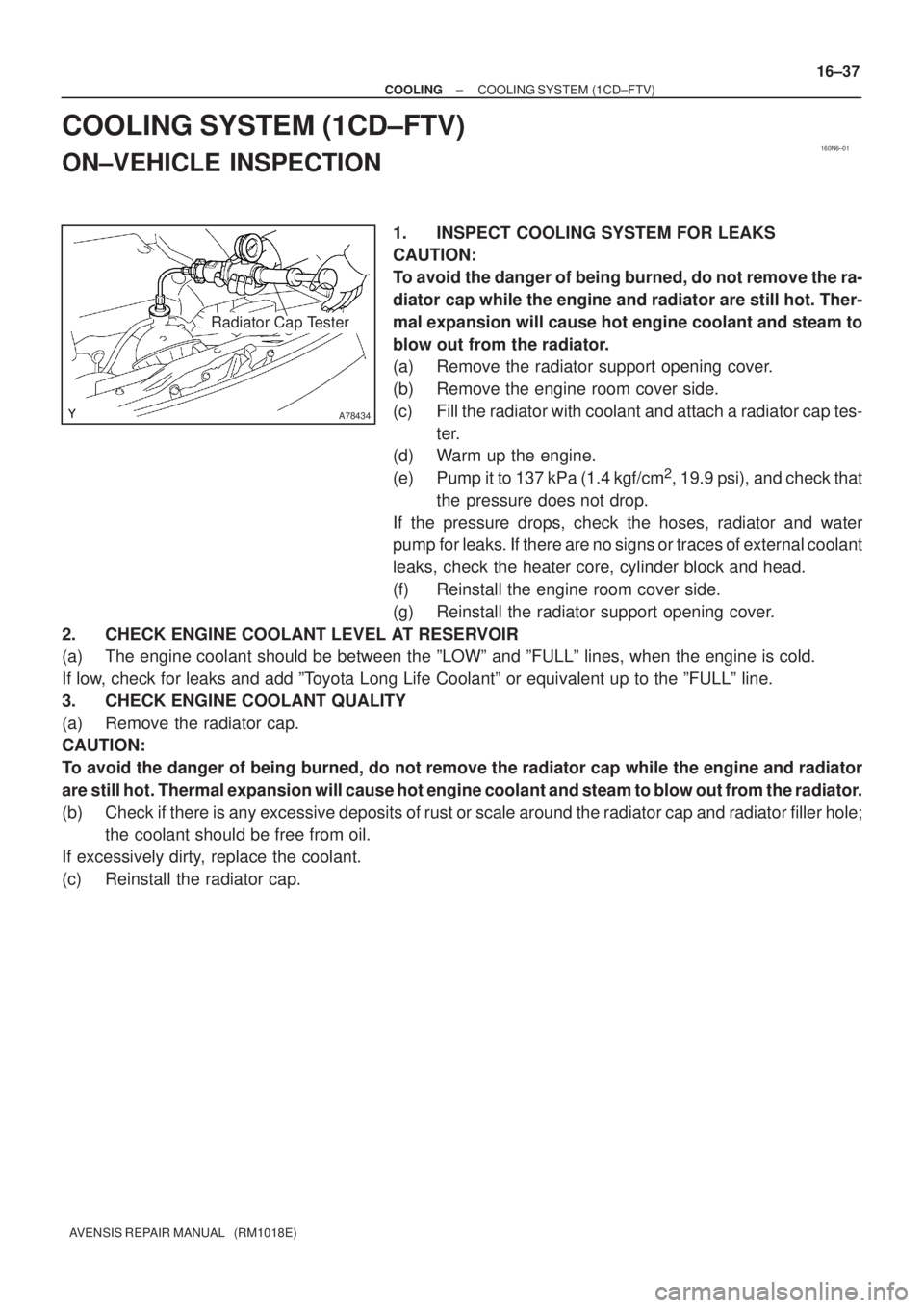
Radiator Cap Tester
± COOLINGCOOLING SYSTEM (1CD±FTV)
16±37
AVENSIS REPAIR MANUAL (RM1018E)
COOLING SYSTEM (1CD±FTV)
ON±VEHICLE INSPECTION
1. INSPECT COOLING SYSTEM FOR LEAKS
CAUTION:
To avoid the danger of being burned, do not remove the ra-
diator cap while the engine and radiator are still hot. Ther-
mal expansion will cause hot engine coolant and steam to
blow out from the radiator.
(a) Remove the radiator support opening cover.
(b) Remove the engine room cover side.
(c) Fill the radiator with coolant and attach a radiator cap tes-
ter.
(d) Warm up the engine.
(e) Pump it to 137 kPa (1.4 kgf/cm
2, 19.9 psi), and check that
the pressure does not drop.
If the pressure drops, check the hoses, radiator and water
pump for leaks. If there are no signs or traces of external coolant
leaks, check the heater core, cylinder block and head.
(f) Reinstall the engine room cover side.
(g) Reinstall the radiator support opening cover.
2. CHECK ENGINE COOLANT LEVEL AT RESERVOIR
(a) The engine coolant should be between the ºLOWº and ºFULLº lines, when the engine is cold.
If low, check for leaks and add ºToyota Long Life Coolantº or equivalent up to the ºFULLº line.
3. CHECK ENGINE COOLANT QUALITY
(a) Remove the radiator cap.
CAUTION:
To avoid the danger of being burned, do not remove the radiator cap while the engine and radiator
are still hot. Thermal expansion will cause hot engine coolant and steam to blow out from the radiator.
(b) Check if there is any excessive deposits of rust or scale around the radiator cap and radiator filler hole;
the coolant should be free from oil.
If excessively dirty, replace the coolant.
(c) Reinstall the radiator cap.
Page 2391 of 5135
160MY±01
A78433
± COOLINGCOOLING SYSTEM (1AZ±FSE)
16±25
AVENSIS REPAIR MANUAL (RM1018E)
COOLING SYSTEM (1AZ±FSE)
ON±VEHICLE INSPECTION
1. INSPECT COOLING SYSTEM FOR LEAKS
CAUTION:
To avoid the danger of being burned, do not remove the ra-
diator cap while the engine and radiator are still hot. Ther-
mal expansion will cause hot engine coolant and steam to
blow out from the radiator.
(a) Remove the radiator support opening cover.
(b) Remove the engine room cover side.
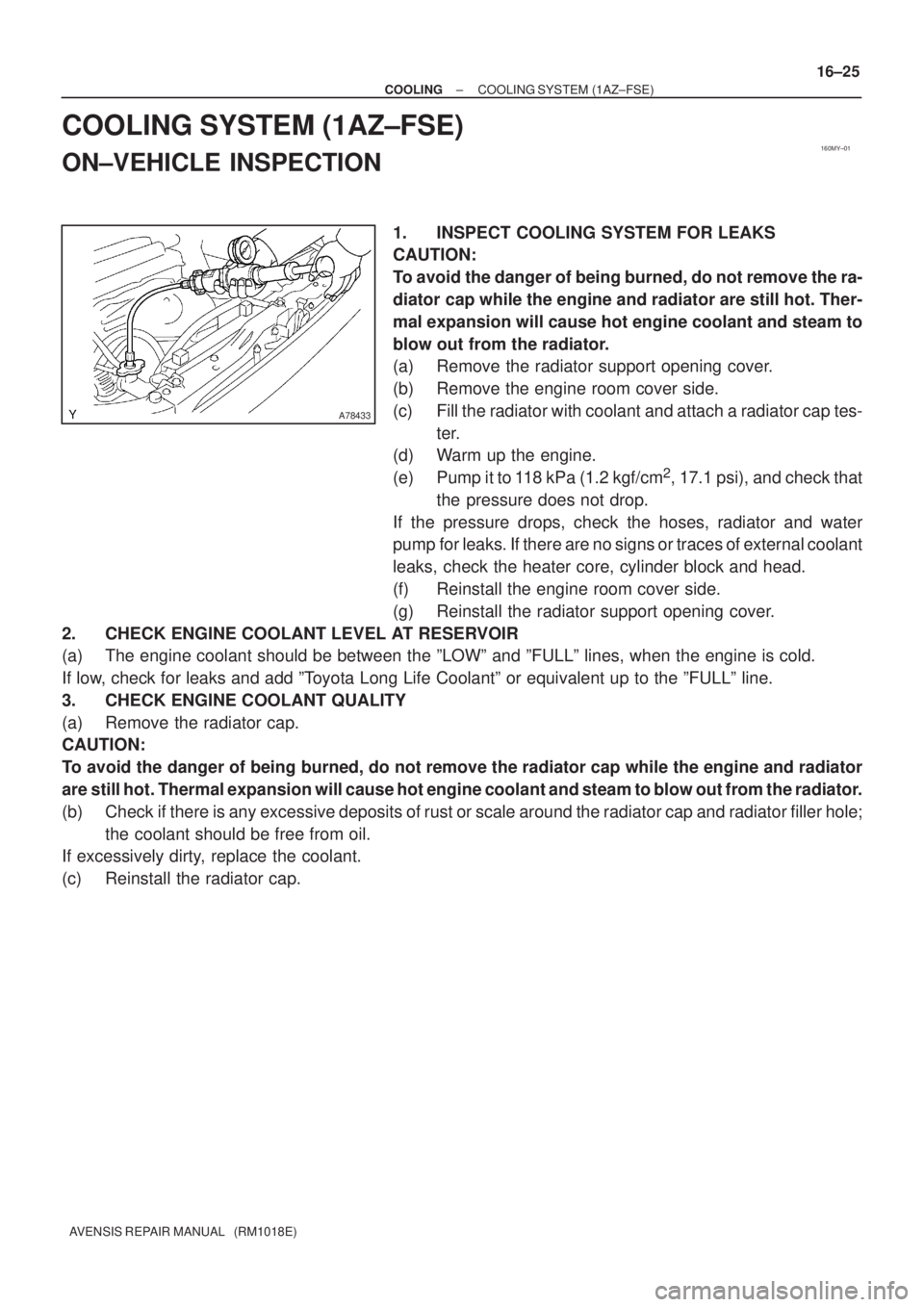
(c) Fill the radiator with coolant and attach a radiator cap tes-
ter.
(d) Warm up the engine.
(e) Pump it to 118 kPa (1.2 kgf/cm
2, 17.1 psi), and check that
the pressure does not drop.
If the pressure drops, check the hoses, radiator and water
pump for leaks. If there are no signs or traces of external coolant
leaks, check the heater core, cylinder block and head.
(f) Reinstall the engine room cover side.
(g) Reinstall the radiator support opening cover.
2. CHECK ENGINE COOLANT LEVEL AT RESERVOIR
(a) The engine coolant should be between the ºLOWº and ºFULLº lines, when the engine is cold.
If low, check for leaks and add ºToyota Long Life Coolantº or equivalent up to the ºFULLº line.
3. CHECK ENGINE COOLANT QUALITY
(a) Remove the radiator cap.
CAUTION:
To avoid the danger of being burned, do not remove the radiator cap while the engine and radiator
are still hot. Thermal expansion will cause hot engine coolant and steam to blow out from the radiator.
(b) Check if there is any excessive deposits of rust or scale around the radiator cap and radiator filler hole;
the coolant should be free from oil.
If excessively dirty, replace the coolant.
(c) Reinstall the radiator cap.
Page 2405 of 5135
17045±03
A56466
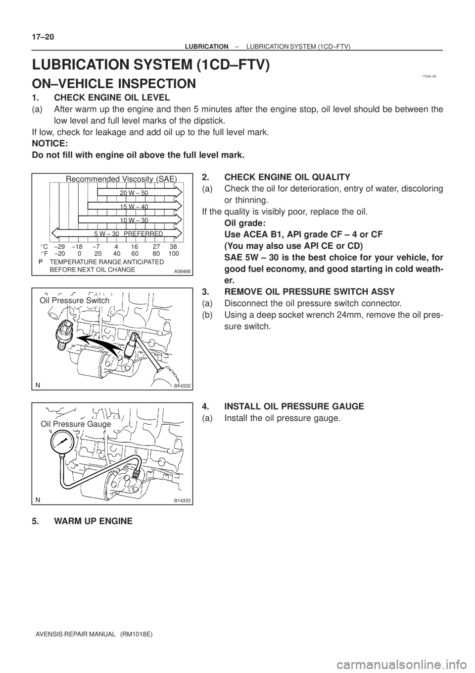
Recommended Viscosity (SAE)
BEFORE NEXT OIL CHANGE TEMPERATURE RANGE ANTICiPATED416 2738
0 20 40 60 80 100 ±29
±20±18 ±7 �C
�F20 W ± 50
15 W ± 40
10 W ± 30
5 W ± 30 PREFERRED
B14332
Oil Pressure Switch
B14333
Oil Pressure Gauge 17±20
± LUBRICATIONLUBRICATION SYSTEM (1CD±FTV)
AVENSIS REPAIR MANUAL (RM1018E)
LUBRICATION SYSTEM (1CD±FTV)
ON±VEHICLE INSPECTION
1. CHECK ENGINE OIL LEVEL
(a) After warm up the engine and then 5 minutes after the engine stop, oil level should be between the
low level and full level marks of the dipstick.
If low, check for leakage and add oil up to the full level mark.
NOTICE:
Do not fill with engine oil above the full level mark.
2. CHECK ENGINE OIL QUALITY
(a) Check the oil for deterioration, entry of water, discoloring
or thinning.
If the quality is visibly poor, replace the oil.
Oil grade:
Use ACEA B1, API grade CF ± 4 or CF
(You may also use API CE or CD)
SAE 5W ± 30 is the best choice for your vehicle, for
good fuel economy, and good starting in cold weath-
er.
3. REMOVE OIL PRESSURE SWITCH ASSY
(a) Disconnect the oil pressure switch connector.
(b) Using a deep socket wrench 24mm, remove the oil pres-
sure switch.
4. INSTALL OIL PRESSURE GAUGE
(a) Install the oil pressure gauge.
5. WARM UP ENGINE
Page 2406 of 5135
P13638
Adhesive
± LUBRICATIONLUBRICATION SYSTEM (1CD±FTV)
17±21
AVENSIS REPAIR MANUAL (RM1018E)
6. CHECK OIL PRESSURE
Oil pressure:
At idle29 kPa (0.3 kgf/cm2, 4.3 psi) or more
At 4,500 rpm245 to 588 kPa (2.5 to 6.0 kgf/cm2, 36 to 85 psi) or more
7. REMOVE OIL PRESSURE GAUGE
8. INSTALL OIL PRESSURE SWITCH ASSY
(a) Apply adhesive to 2 or 3 threads of the oil pressure switch.
Adhesive:
Part No. 08833 ± 00080, THREE BOND 1344,
LOCTITE 242 or equivalent
(b) Using a deep socket wrench 24mm, install the oil pres-
sure switch.
Torque: 15 N�m (153 kgf�cm, 11 ft�lbf)
NOTICE:
Do not start the engine within 1 hour after the installation.
(c) Connect the oil pressure switch connector.
9. START ENGINE AND CHECK FOR LEAKS
Page 2408 of 5135
170FX±01
A77339
±
LUBRICATION OIL PUMP ASSY(1AZ±FSE)
17±15
AVENSIS REPAIR MANUAL (RM1018E)
OIL PUMP ASSY(1AZ±FSE)
REPLACEMENT
1.DISCHARGE FUEL SYSTEM PRESSURE (See page 11±30)
2.REMOVE FRONT WHEEL RH
3.REMOVE RADIATOR SUPPORT OPENING COVER
4.REMOVE ENGINE ROOM COVER SIDE
5.REMOVE ENGINE UNDER COVER RH
6.REMOVE ENGINE UNDER COVER LH
7.DRAIN ENGINE OIL
(a)Install a new gasket and drain plug after draining engine oil.
Torque: 25 N �m (250 kgf �cm,18 ft �lbf)
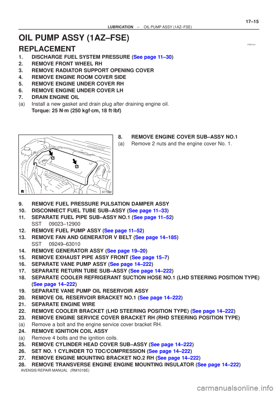
8.REMOVE ENGINE COVER SUB±ASSY NO.1
(a)Remove 2 nuts and the engine cover No. 1.
9.REMOVE FUEL PRESSURE PULSATION DAMPER ASSY
10.DISCONNECT FUEL TUBE SUB±ASSY (See page 11±33)
11.SEPARATE FUEL PIPE SUB±ASSY NO.1 (See page 11±52) SST 09023±12900
12.REMOVE FUEL PUMP ASSY (See page 11±52)
13.REMOVE FAN AND GENERATOR V BELT (See page 14±185) SST 09249±63010
14.REMOVE GENERATOR ASSY (See page 19±20)
15.REMOVE EXHAUST PIPE ASSY FRONT (See page 15±7)
16.SEPARATE VANE PUMP ASSY (See page 14±222)
17.SEPARATE RETURN TUBE SUB±ASSY (See page 14±222)
18. SEPARATE COOLER REFRIGERANT SUCTION HOSE NO.1 (LHD STEERING POSITION TYPE) (See page 14±222)
19. SEPARATE VANE PUMP OIL RESERVOIR ASSY
20.REMOVE OIL RESERVOIR BRACKET NO.1 (See page 14±222)
21. SEPARATE ENGINE WIRE
22.REMOVE COOLER BRACKET (LHD STEERING POSITION TYPE) (See page 14±222)
23. REMOVE ENGINE SERVICE COVER BRACKET RH (RHD STEERING POSITION TYPE)
(a) Remove a bolt and the engine service cover bracket RH.
24. REMOVE IGNITION COIL ASSY
(a) Remove 4 bolts and the ignition coils.
25.REMOVE CYLINDER HEAD COVER SUB±ASSY (See page 14±222)
26.SET NO. 1 CYLINDER TO TDC/COMPRESSION (See page 14±222)
27.REMOVE ENGINE MOUNTING BRACKET NO.2 RH (See page 14±222)
28.REMOVE TRANSVERSE ENGINE ENGINE MOUNTING INSULATOR (See page 14±222)
Page 2411 of 5135
17±18
±
LUBRICATION OIL PUMP ASSY(1AZ±FSE)
AVENSIS REPAIR MANUAL (RM1018E)
64.INSTALL OIL RESERVOIR BRACKET NO.1 Torque: 8.0 N �m (82 kgf �cm,71 in. �lbf)
65.INSTALL COOLER REFRIGERANT SUCTION HOSE NO.1 (LHD STEERING POSITION TYPE)
Torque: 9.0 N �m (92 kgf �cm,80 in. �lbf)
66.INSTALL RETURN TUBE SUB±ASSY Torque: 8.0 N �m (82 kgf �cm,71 in. �lbf)
67.INSTALL IGNITION COIL ASSY
Torque: 9.0 N �m (92 kgf �cm,80 in. �lbf)
68.INSTALL VANE PUMP ASSY Torque: 37 N �m (377 kgf �cm,27 ft �lbf)
69.INSTALL EXHAUST PIPE ASSY FRONT (See page 15±7)
70.INSTALL GENERATOR ASSY (See page 19±20)
71.INSTALL FAN AND GENERATOR V BELT (See page 14±185) SST 09249±63010
72.INSTALL FUEL PUMP ASSY (See page 11±52)
73.INSTALL FUEL PIPE SUB±ASSY NO.1 (See page 11±52) SST 09023±12900
74.INSTALL FUEL TUBE SUB±ASSY (See page 11±33)
75.INSTALL FUEL PRESSURE PULSATION DAMPER ASSY (See page 11±52)
76. ADD ENGINE OIL
77. CHECK FOR ENGINE OIL LEAKS
78. CHECK FUEL LEAK
79. INSTALL ENGINE COVER SUB±ASSY NO.1 Torque: 7.0 N �m (71 kgf �cm, 62 in. �lbf)
80. INSTALL FRONT WHEEL RH
Torque: 103 N �m (1,050 kgf �cm, 76 ft �lbf)
Page 2412 of 5135
1700E±07
A56466
Recommended Viscosity (SAE)
BEFORE NEXT OIL CHANGE TEMPERATURE RANGE ANTICiPATED416 2738
0 20 40 60 80 100 ±29
±20±18 ±7 �C
�F20 W ± 50
15 W ± 40
10 W ± 30
5 W ± 30 PREFERRED
B67536
B67537Oil Pressure Gauge
± LUBRICATIONLUBRICATION SYSTEM (1AZ±FSE)
17±13
AVENSIS REPAIR MANUAL (RM1018E)
LUBRICATION SYSTEM (1AZ±FSE)
ON±VEHICLE INSPECTION
1. CHECK ENGINE OIL LEVEL
(a) After warm up the engine and then 5 minutes after the engine stop, oil level should be between the
low level and full level marks of the dipstick.
If low, check for leakage and add oil up to the full level mark.
NOTICE:
Do not fill with engine oil above the full level mark.
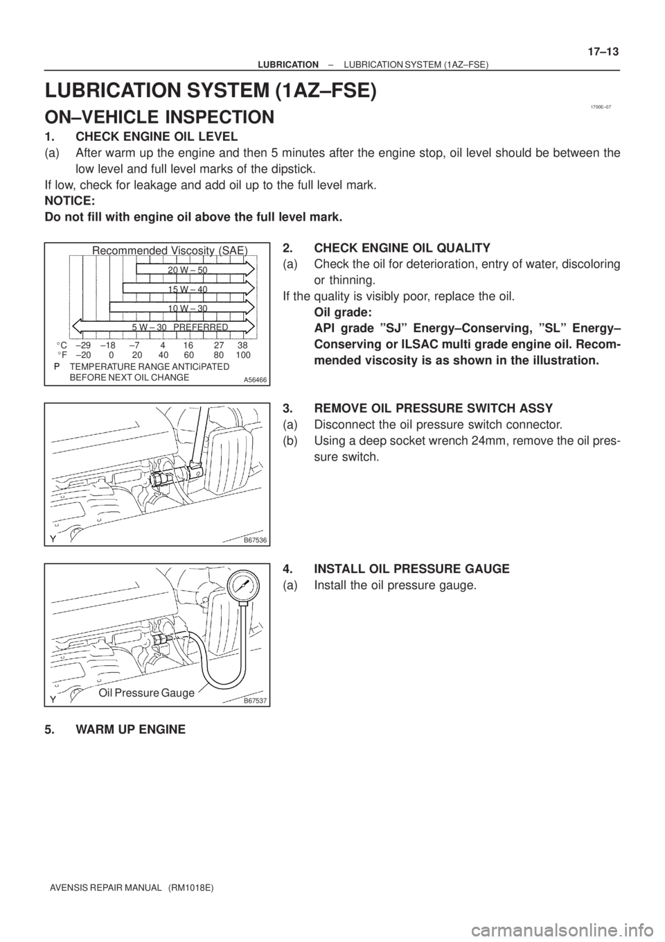
2. CHECK ENGINE OIL QUALITY
(a) Check the oil for deterioration, entry of water, discoloring
or thinning.
If the quality is visibly poor, replace the oil.
Oil grade:
API grade ºSJº Energy±Conserving, ºSLº Energy±
Conserving or ILSAC multi grade engine oil. Recom-
mended viscosity is as shown in the illustration.
3. REMOVE OIL PRESSURE SWITCH ASSY
(a) Disconnect the oil pressure switch connector.
(b) Using a deep socket wrench 24mm, remove the oil pres-
sure switch.
4. INSTALL OIL PRESSURE GAUGE
(a) Install the oil pressure gauge.
5. WARM UP ENGINE
Page 2413 of 5135
Adhesive
A50082
17±14
± LUBRICATIONLUBRICATION SYSTEM (1AZ±FSE)
AVENSIS REPAIR MANUAL (RM1018E)
6. CHECK OIL PRESSURE
Oil pressure:
At idle29 kPa (0.3 kgf/cm2, 4.3 psi) or more
At 3,000 rpm245 to 539 kPa (2.5 to 5.5 kgf/cm2, 36 to 78 psi) or more
7. REMOVE OIL PRESSURE GAUGE
8. INSTALL OIL PRESSURE SWITCH ASSY
(a) Apply adhesive to 2 or 3 threads of the oil pressure switch.
Adhesive:
Part No. 08833±00080, THREE BOND 1344,
LOCTITE 242 or equivalent
(b) Using a deep socket wrench 24mm, install the oil pres-
sure switch.
Torque: 15 N�m (153 kgf�cm, 11 ft�lbf)
NOTICE:
Do not start the engine within 1 hour after the installation.
(c) Connect the oil pressure switch connector.
9. START ENGINE AND CHECK FOR LEAKS