Page 2018 of 5135

A62191
Advanced
Side Path Retard
Side Path
A62192
Hold Pressure
DecompressAdvanced
Side Path Retard
Side Path
A62193
Straight Pin Fringe Bolt
A62194
Straight Pin
Key Groove
14±70
± ENGINE MECHANICALCAMSHAFT (1ZZ±FE/3ZZ±FE)
AVENSIS REPAIR MANUAL (RM1018E)
(c) Put air pressure into two broken paths (the advance side
path and the retard side path) with about 150 kPa {1.5
kgf�cm}.
CAUTION:
Cover the paths with shop rag to avoid oil splashing.
(d) Confirm if the camshaft timing gear assembly revolves in
the timing advance direction when weakening the air
pressure of the timing retard path.
HINT:
When the lock pin is released, the camshaft timing gear re-
volves in the advance direction.
(e) When the camshaft timing gear comes to the most ad-
vanced position, take out the air pressure of the timing re-
tard side path, next, take out that of timing advance side
path.
CAUTION:
Camshaft timing gear assembly occasionally shifts to the
retard side abruptly, if the air compression of the advanced
side path is released first. It often causes the breakage of
the lock pin.
(f) Remove the fringe bolt of camshaft timing gear assembly.
NOTICE:
�Be sure not to remove the other 4 bolts.
�In case of reusing the camshaft timing gear, release
the straight pin lock first, and then install the gear.
17. INSTALL CAMSHAFT TIMING GEAR ASSY
(a) Put the camshaft timing gear assembly and the camshaft
together with the straight pin off the key groove.
(b) Turn the camshaft timing gear assembly clockwise (as
shown in the illustration) while pushing it lightly against
the camshaft. Push further at the position where the pin
gets into the groove.
CAUTION:
Be sure not to turn the camshaft timing gear to the retard
angle side (to the right angle).
Page 2051 of 5135
A64027
A64028
B00084
A76692
A64029
±
ENGINE MECHANICAL PARTIAL ENGINE ASSY (1ZZ±FE/3ZZ±FE)
14±35
AVENSIS REPAIR MANUAL (RM1018E)
73. REMOVE WATER BY±PASS PIPE NO.1
(a) Disconnect the knock sensor cramp.
(b) Remove the 2 bolts and 2 nuts, then detach the water by±
pass pipe and the gasket.
74. REMOVE WATER INLET
(a) Remove the 2 nuts and the water inlet.
75. REMOVE THERMOSTAT
76. REMOVE ENGINE OIL PRESSURE SWITCH ASSY (See page 17±1)
77. REMOVE CAMSHAFT POSITION SENSOR
(a) Remove the bolt and the camshaft position sensor.
78. REMOVE CRANKSHAFT POSITION SENSOR
(a) Remove the 2 bolts and the crankshaft position sensor.
79. REMOVE KNOCK SENSOR
(a) Remove the nut and the knock sensor.
Page 2067 of 5135
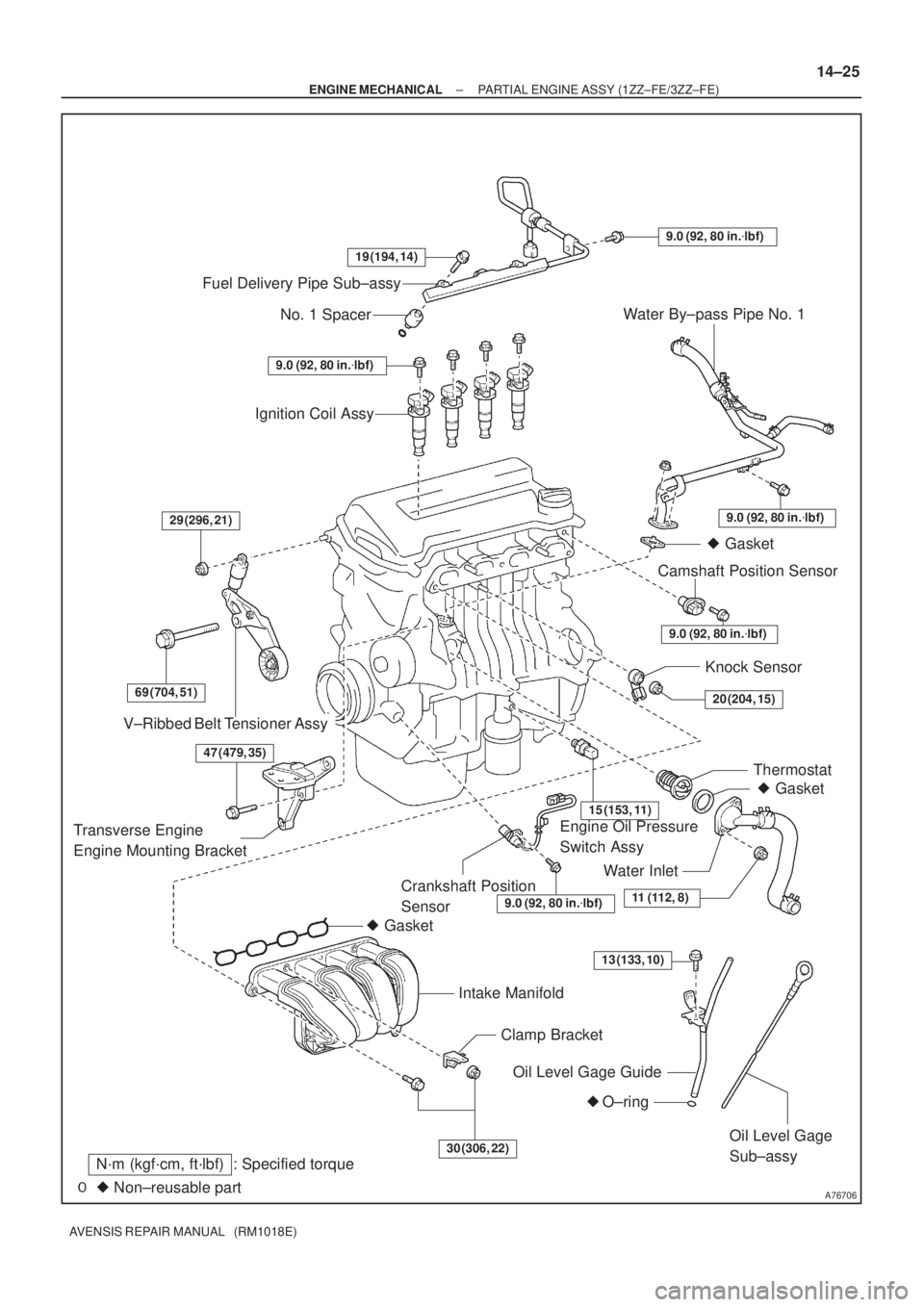
A76706
Fuel Delivery Pipe Sub±assy
No. 1 Spacer
Ignition Coil Assy
V±Ribbed Belt Tensioner Assy
� Gasket
Intake Manifold
Clamp Bracket
Oil Level Gage Guide
� O±ring
Oil Level Gage
Sub±assy
Crankshaft Position
Sensor� Gasket Thermostat Knock Sensor
Engine Oil Pressure
Switch AssyCamshaft Position Sensor� Gasket Water By±pass Pipe No. 1
� Non±reusable part
N´m (kgf´cm, ft´lbf) : Specified torque
Water Inlet
19 (194, 14)
9.0 (92, 80 in.�lbf)
9.0 (92, 80 in.�lbf)
9.0 (92, 80 in.�lbf)
9.0 (92, 80 in.�lbf)29 (296, 21)
69 (704, 51)
15 (153, 11)
20 (204, 15)
11 (112, 8)
30 (306, 22)
9.0 (92, 80 in.�lbf)
Transverse Engine
Engine Mounting Bracket
13 (133, 10)
47 (479, 35)
± ENGINE MECHANICALPARTIAL ENGINE ASSY (1ZZ±FE/3ZZ±FE)
14±25
AVENSIS REPAIR MANUAL (RM1018E)
Page 2069 of 5135

14±121
AVENSIS REPAIR MANUAL (RM1018E)
REPLACEMENT
1.DISCHARGE FUEL SYSTEM PRESSURE (See page 11±19)
2.REMOVE FRONT WHEELS")
141BF±01
A77281
A77301
±
ENGINE MECHANICAL PARTIAL ENGINE ASSY(1AZ±FE)
14±121
AVENSIS REPAIR MANUAL (RM1018E)
REPLACEMENT
1.DISCHARGE FUEL SYSTEM PRESSURE (See page 11±19)
2.REMOVE FRONT WHEELS
3.REMOVE RADIATOR SUPPORT OPENING COVER
4.REMOVE ENGINE ROOM COVER SIDE
5.REMOVE ENGINE UNDER COVER RH
6.REMOVE ENGINE UNDER COVER LH
7.DRAIN COOLANT (See page 16±19)
8.DRAIN ENGINE OIL
(a)Install a new gasket and the drain plug after draining engine oil.
Torque: 25 N �m (255 kgf �cm,18 ft �lbf)
9.DRAIN MANUAL TRANSAXLE OIL (M/T TRANSAXLE) Torque: 49 N �m (500 kgf �cm,36 ft �lbf)
10.DRAIN AUTOMATIC TRANSAXLE FLUID (A/T TRANSAXLE) (See page 40±2)
11.REMOVE ENGINE COVER SUB±ASSY NO.1
(a)Remove 2 nuts and the cylinder head cover No. 1.
12.DISCONNECT RADIATOR HOSE INLET
13.DISCONNECT RADIATOR HOSE OUTLET 14.SEPARATE RADIATOR RELAY BLOCK
(a)Remove 2 bolts and separate the radiator relay block.
15.SEPARATE COOLER REFRIGERANT SUCTION HOSE NO.1 (RHD(W/ AIR CONDITIONER) STEERING POSITION TYPE)
(a)Remove a bolt and separate the suction hose No. 1.
16.REMOVE RADIATOR ASSY (See page 16±24)
17.REMOVE FAN AND GENERATOR V BELT (See page 14±105)
18.REMOVE GENERATOR ASSY (See page 19±20)
19. REMOVE COMPRESSOR AND MAGNETIC CLUTCH (W/ AIR CONDITIONING)
(a) Remove 4 bolts and separate the compressor and magnetic clutch.
HINT:
Secure the hoses off to the side instead of detaching.
Page 2075 of 5135

14±127
AVENSIS REPAIR MANUAL (RM1018E)
63.SEPARATE VANE PUMP ASSY
(a)Disconnect the PS oil pressure switch connector.
(b)Remove th")
A77402SST
A56446
±
ENGINE MECHANICAL PARTIAL ENGINE ASSY(1AZ±FE)
14±127
AVENSIS REPAIR MANUAL (RM1018E)
63.SEPARATE VANE PUMP ASSY
(a)Disconnect the PS oil pressure switch connector.
(b)Remove the 2 bolts and separate the vane pump from the engine.
64.REMOVE STARTER ASSY (See page 19±12)
65.REMOVE FRONT SUSPENSION CROSSMEMBER W/CENTER MEMBER
(a)Remove the through bolt and nut from the engine mounting insulator FR.
(b)Remove the through bolt and nut from the engine mounting insulator RR.
66.REMOVE FRONT DRIVE SHAFT ASSY LH (See page 30±6)
67.REMOVE FRONT DRIVE SHAFT ASSY RH (See page 30±6)
68.REMOVE MANUAL TRANSAXLE ASSY (M/T TRANSAXLE) (See page 41±24)
69.REMOVE AUTOMATIC TRANSAXLE ASSY (A/T TRANSAXLE) (See page 40±25)
70.REMOVE CLUTCH COVER ASSY (M/T TRANSAXLE) (See page 42±26)
71.REMOVE CLUTCH DISC ASSY (M/T TRANSAXLE) (See page 42±26)
72. REMOVE DRIVE PLATE AND RING GEAR ORFLYWHEEL
(a) Using SST, fix the crankshaft pulley and remove the drive plate and ring gear or flywheel.
SST 09213±54015 (91651±60855), 09330±00021
73. REMOVE CAMSHAFT TIMING OIL CONTROL VALVE ASSY (W/ VVT±i)
(a) Remove a bolt, O±ring and the camshaft timing oil control valve. 74. REMOVE INTAKE MANIFOLD
(a) Remove the 5 bolts and 2 nuts, and then remove the in-take manifold.
75. REMOVE VENTILATION HOSE
76. REMOVE VENTILATION HOSE NO.2
77. REMOVE ENGINE WIRE
78. REMOVE INTAKE MANIFOLD INSULATOR NO.1
79. REMOVE OIL LEVEL GAGE SUB±ASSY
80. REMOVE OIL LEVEL GAGE GUIDE
81. REMOVE MANIFOLD CONVERTER INSULATOR NO.1
(a) Remove the 4 bolts and the manifold converter insulator No. 1.
Page 2076 of 5135

AVENSIS REPAIR MANUAL (RM1018E)
82.REMOVE EXHAUST MANIFOLD CONVERTER SUB±ASSY
(a)Remove the")
A60067
A52497
A32676
A78645
Oil Pressure Switch
14±128
±
ENGINE MECHANICAL PARTIAL ENGINE ASSY(1AZ±FE)
AVENSIS REPAIR MANUAL (RM1018E)
82.REMOVE EXHAUST MANIFOLD CONVERTER SUB±ASSY
(a)Remove the 3 bolts and 2 nuts, and then detach the No.
1 and No. 2 exhaust manifold stays.
(b)Remove the 5 nuts, and then remove the exhaust man- ifold converter and gasket.
83.REMOVE WATER INLET
(a)Remove the 2 nuts and the water inlet.
84.REMOVE THERMOSTAT
85.REMOVE IGNITION COIL ASSY
(a)Remove the 4 bolts and the 4 ignition coils. 86.REMOVE V±RIBBED BELT TENSIONER ASSY
(a)Remove the bolt and nut, and then remove the V±ribbedbelt tensioner.
87.REMOVE DRIVE SHAFT BEARING BRACKET
(a)Remove the 3 bolts and the drive shaft bearing bracket.
88.REMOVE FUEL DELIVERY PIPE W/INJECTOR (See page 11±26)
89. REMOVE WATER BY±PASS PIPE NO.1
(a) Remove the bolt and 2 nuts, and then detach the water by±pass pipe No\
. 1. 90. REMOVE ENGINE OIL PRESSURE SWITCH ASSY
(a) Using SST, remove the engine oil pressure switch.SST 09268±46021
Page 2077 of 5135

14±129
AVENSIS REPAIR MANUAL (RM1018E)
91.REMOVE KNOCK SENSOR
(a)Remove the nut and the knock sensor.
92.REMOVE ENGINE COOLANT TEMPER")
A77332
23
145
±
ENGINE MECHANICAL PARTIAL ENGINE ASSY(1AZ±FE)
14±129
AVENSIS REPAIR MANUAL (RM1018E)
91.REMOVE KNOCK SENSOR
(a)Remove the nut and the knock sensor.
92.REMOVE ENGINE COOLANT TEMPERATURE SENSOR
(a)Using SST, remove the engine coolant temperature sensor.
SST09817±33190
93.REPLACE PARTIAL ENGINE ASSY
94.INSTALL ENGINE COOLANT TEMPERATURE SENSOR
(a)Install a new gasket to the engine coolant temperature sensor.
(b)Install the engine coolant temperature sensor. Torque: 20 N �m (208 kgf �cm,15 ft �lbf)
SST09817±33190
95.INSTALL KNOCK SENSOR
Torque: 20 N �m (208 kgf �cm,15 ft �lbf)
96.INSTALL ENGINE OIL PRESSURE SWITCH ASSY
(a)Clean the threads of the oil pressure switch, apply adhesive there. Adhesive: Part No. 08833±00080 THREE BOND 1344 or equivalent
(b)Install the oil pressure switch. Torque: 15 N �m (153 kgf �cm,11 ft �lbf)
97.INSTALL WATER BY±PASS PIPE NO.1
(a)Install a new gasket and the water by±pass pipe No. 1 with the bolt a\
nd 2 nuts. Torque: 9.0 N �m (92 kgf �cm,80 in. �lbf)
98.INSTALL FUEL DELIVERY PIPE W/INJECTOR (See page 11±26)
99.INSTALL DRIVE SHAFT BEARING BRACKET Torque: 54 N �m (551 kgf �cm,40 ft �lbf)
100.INSTALL V±RIBBED BELT TENSIONER ASSY
Torque: 60 N �m (607 kgf �cm,44 ft �lbf)
101.INSTALL IGNITION COIL ASSY Torque: 9.0 N �m (92 kgf �cm,80 in. �lbf)
102.INSTALL THERMOSTAT (See page 16±23)
103. INSTALL WATER INLET
Torque: 9.0 N �m (92 kgf �cm, 80 in. �lbf)
104. I N S TA L L E X HAUST MANIFOLD CONVERTER
SUB±ASSY
(a) Install a new gasket and the exhaust manifold converter
with the 5 nuts.
Torque: 37 N �m (378 kgf �cm, 27 ft �lbf)
Page 2092 of 5135
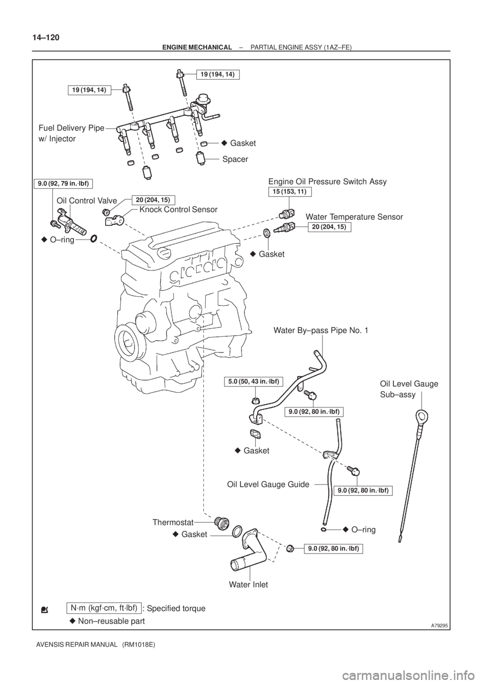
A79295
N´m (kgf´cm, ft´lbf)
: Specified torque
� Non±reusable part
5.0 (50, 43 in.�lbf)
� O±ring
� Gasket� Gasket� Gasket � Gasket
� O±ring
15 (153, 11)
20 (204, 15)
9.0 (92, 80 in.�lbf)
9.0 (92, 80 in.�lbf)
Fuel Delivery Pipe
w/ Injector
Oil Control Valve
Knock Control SensorSpacer
Water By±pass Pipe No. 1
Oil Level Gauge
Sub±assy
Oil Level Gauge Guide
Water Inlet
9.0 (92, 79 in.�lbf)Engine Oil Pressure Switch Assy
Water Temperature Sensor
Thermostat
9.0 (92, 80 in.�lbf)
19 (194, 14)
19 (194, 14)
20 (204, 15)
14±120
± ENGINE MECHANICALPARTIAL ENGINE ASSY (1AZ±FE)
AVENSIS REPAIR MANUAL (RM1018E)

14±35
AVENSIS REPAIR MANUAL (RM1018E)
73. REMOVE WATER BY±PASS PIPE NO.1
(a) Disconnect the knock sens")