Page 2206 of 5135

AVENSIS REPAIR MANUAL (RM1018E)
61.SEPARATE VANE PUMP ASSY
(a)Disconnect the PS oil pressure switch connector.
(b)Remove")
A77331
SST
A77353
14±210
±
ENGINE MECHANICAL PARTIAL ENGINE ASSY(1AZ±FSE)
AVENSIS REPAIR MANUAL (RM1018E)
61.SEPARATE VANE PUMP ASSY
(a)Disconnect the PS oil pressure switch connector.
(b)Remove the 2 bolts and separate the vane pump from the engine.
62.REMOVE STARTER ASSY (See page 19±12)
63. REMOVE FRONT SUSPENSION CROSSMEMBER W/CENTER MEMBER
(a) Remove the through bolt and nut from the engine mounting insulator FR.
(b) Remove the through bolt and nut from the engine mounting insulator RR.
64.REMOVE FRONT DRIVE SHAFT ASSY LH (See page 30±6)
65.REMOVE FRONT DRIVE SHAFT ASSY RH (See page 30±6)
66.REMOVE MANUAL TRANSAXLE ASSY (M/T TRANSAXLE) (See page 41±24)
67.REMOVE AUTOMATIC TRANSAXLE ASSY (A/T TRANSAXLE) (See page 40±25)
68.REMOVE CLUTCH COVER ASSY (M/T TRANSAXLE) (See page 42±26)
69.REMOVE CLUTCH DISC ASSY (M/T TRANSAXLE) (See page 42±26) 70. REMOVE DRIVE PLATE AND RING GEAR ORFLYWHEEL
(a) Using SST, fix the crankshaft pulley and remove the drive plate and ring gear or flywheel.
SST 09213±54015 (91651±60855), 09330±00021
71. REMOVE CAMSHAFT TIMING OIL CONTROL VALVE ASSY
(a) Remove the bolt, O±ring and the camshaft timing oil control valve.
72. REMOVE THROTTLE BODY BRACKET
(a) Separate the engine wire.
(b) Remove the 4 bolts and the throttle body bracket.
73.REMOVE THROTTLE BODY ASSY (See page 10±44)
74. REMOVE FUEL PRESSURE PULSATION DAMPER ASSY
75. DISCONNECT FUEL TUBE SUB±ASSY
76.REMOVE FUEL PIPE SUB±ASSY NO.1 (See page 11±52)
77.REMOVE FUEL PUMP ASSY (See page 11±52)
78. REMOVE WATER BY±PASS HOSE 79. REMOVE INTAKE MANIFOLD
(a) Remove the 5 bolts and 2 nuts.
(b) Remove the intake manifold and the insulator.
Page 2208 of 5135

AVENSIS REPAIR MANUAL (RM1018E)
94.REMOVE WATER BY±PASS PIPE NO.1
(a)Remove the 2 bolts and 2 nuts.
(b)Remove t")
A78645
Oil Pressure Switch
14±212
±
ENGINE MECHANICAL PARTIAL ENGINE ASSY(1AZ±FSE)
AVENSIS REPAIR MANUAL (RM1018E)
94.REMOVE WATER BY±PASS PIPE NO.1
(a)Remove the 2 bolts and 2 nuts.
(b)Remove the water by±pass pipe No. 1 and a gasket.
95.REMOVE KNOCK SENSOR
(a)Remove the nut and the knock sensor. 96.REMOVE ENGINE OIL PRESSURE SWITCH ASSY
(a)Using SST, remove the engine oil pressure switch.SST09268±46021
97.REMOVE E.F.I. ENGINE COOLANT TEMPERATURE SENSOR
(a)Using a SST, remove the coolant temperature sensor SST09817±33190
98.REPLACE PARTIAL ENGINE ASSY
99.INSTALL E.F.I. ENGINE COOLANT TEMPERATURE SENSOR
(a)Install a new gasket to the engine coolant temperature sensor.
(b)Using SST, install the engine coolant temperature sensor. SST09817±33190
Torque: 20 N �m (208 kgf �cm,15 ft �lbf)
100.INSTALL ENGINE OIL PRESSURE SWITCH ASSY
(a)Clean the threads of the oil pressure switch, apply adhesive there.
Adhesive: Part No. 08833 ± 00080 THREE BOND 1344 or equivalent.
(b)Install the oil pressure switch. Torque: 15 N �m (153 kgf �cm,11 ft �lbf)
SST09268±46021
101.INSTALL KNOCK SENSOR Torque: 20 N �m (208 kgf �cm,15 ft �lbf)
102.INSTALL WATER BY±PASS PIPE NO.1
(a)Install the water by±pass pipe No. 1 and a new gasket.
(b)Install the 2 bolts and 2 nuts. Torque: 9.0 N �m (92 kgf �cm,80 in. �lbf)
103.INSTALL THERMOSTAT (See page 16±35)
104. INSTALL WATER INLET Torque: 9.0 N �m (92 kgf �cm, 80 in. �lbf)
105. INSTALL OIL LEVEL GAGE GUIDE
(a) Apply a light coat of engine oil to the O±ring, install it to the oil\
level gauge guide.
(b) Install the oil level gauge and guide with the bolt. Torque: 9.0 N �m (92 kgf �cm, 80 in. �lbf)
Page 2209 of 5135

14±213
AVENSIS REPAIR MANUAL (RM1018E)
106.INSTALL EXHAUST MANIFOLD CONVERTER
SUB±ASSY
(a)Install a new gasket and the exhau")
A77332
23
145
A77350
±
ENGINE MECHANICAL PARTIAL ENGINE ASSY(1AZ±FSE)
14±213
AVENSIS REPAIR MANUAL (RM1018E)
106.INSTALL EXHAUST MANIFOLD CONVERTER
SUB±ASSY
(a)Install a new gasket and the exhaust manifold converter
with the 5 nuts.
Torque: 37 N �m (378 kgf �cm, 27 ft �lbf)
(b)Install the No. 1 and No. 2 exhaust manifold stays with the 2 bolts and 2 nuts.
Torque: 44 N �m (449 kgf �cm, 32 ft �lbf)
107.INSTALL EXHAUST MANIFOLD HEAT INSULATOR NO.1 Torque: 12 N �m (122 kgf �cm,9.0 ft �lbf)
108.INSTALL V±RIBBED BELT TENSIONER ASSY Torque: 60 N �m (607 kgf �cm,44 ft �lbf)
109.INSTALL IGNITION COIL ASSY
Torque: 9.0 N �m (92 kgf �cm,80 in. �lbf)
110.INSTALL FUEL INJECTOR ASSY (See page 11±42)
111.INSTALL FUEL DELIVERY PIPE SUB±ASSY (See page 11±42)
112.INSTALL NOZZLE HOLDER CLAMP (See page 11±42)
113. INSTALL SURGE TANK STAY NO.1
(a) Install the surge tank stay with insulator No. 2. Torque: 21 N �m (210 kgf �cm, 15 ft �lbf)
114. INSTALL INTAKE MANIFOLD
(a) Install a new gasket on the cylinder head.
(b) Install the intake manifold with the 5 bolts and 2 nuts. Torque: 30 N �m (306 kgf �cm, 22 ft �lbf)
115.INSTALL FUEL PUMP ASSY (See page 11±52)
116.INSTALL FUEL PIPE SUB±ASSY NO.1 (See page 11±52) SST 09023±12900
117.INSTALL FUEL PRESSURE PULSATION DAMPER ASSY (See page 11±49)
118.INSTALL THROTTLE BODY ASSY (See page 10±44)
119. INSTALL THROTTLE BODY BRACKET Torque: 21 N �m (210 kgf �cm, 15 ft �lbf)
120. INSTALL CAMSHAFT TIMING OIL CONTROL VALVE ASSY
(a) Apply a light coat of engine oil to the new O±ring and install it to the c\
amshaft timing oil control valve.
(b) Install the camshaft oil control valve with the bolt. Torque: 9.0 N �m (92 kgf �cm, 79 in. �lbf)
Page 2223 of 5135
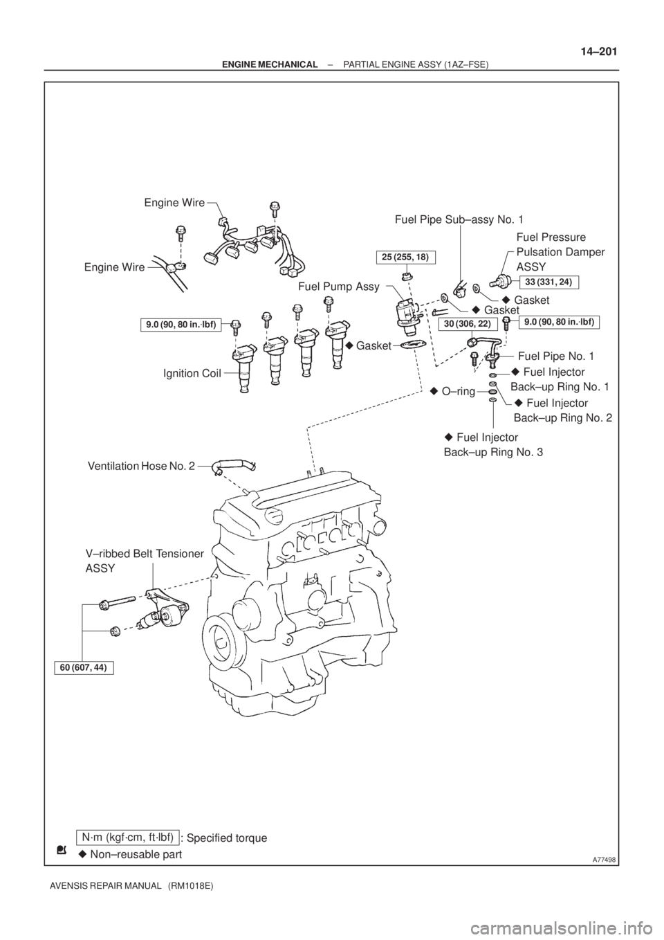
A77498
Engine Wire
Engine Wire
Ignition Coil
Ventilation Hose No. 2
V±ribbed Belt Tensioner
ASSYFuel Pipe Sub±assy No. 1
� Gasket
� Gasket
� Gasket Fuel Pump AssyFuel Pressure
Pulsation Damper
ASSY
9.0 (90, 80 in.�lbf)
60 (607, 44)
25 (255, 18)
33 (331, 24)
9.0 (90, 80 in.�lbf)
Fuel Pipe No. 1
� Fuel Injector
Back±up Ring No. 1
� O±ring
� Fuel Injector
Back±up Ring No. 3� Fuel Injector
Back±up Ring No. 2
N´m (kgf´cm, ft´lbf)
: Specified torque
� Non±reusable part
30 (306, 22)
± ENGINE MECHANICALPARTIAL ENGINE ASSY (1AZ±FSE)
14±201
AVENSIS REPAIR MANUAL (RM1018E)
Page 2225 of 5135
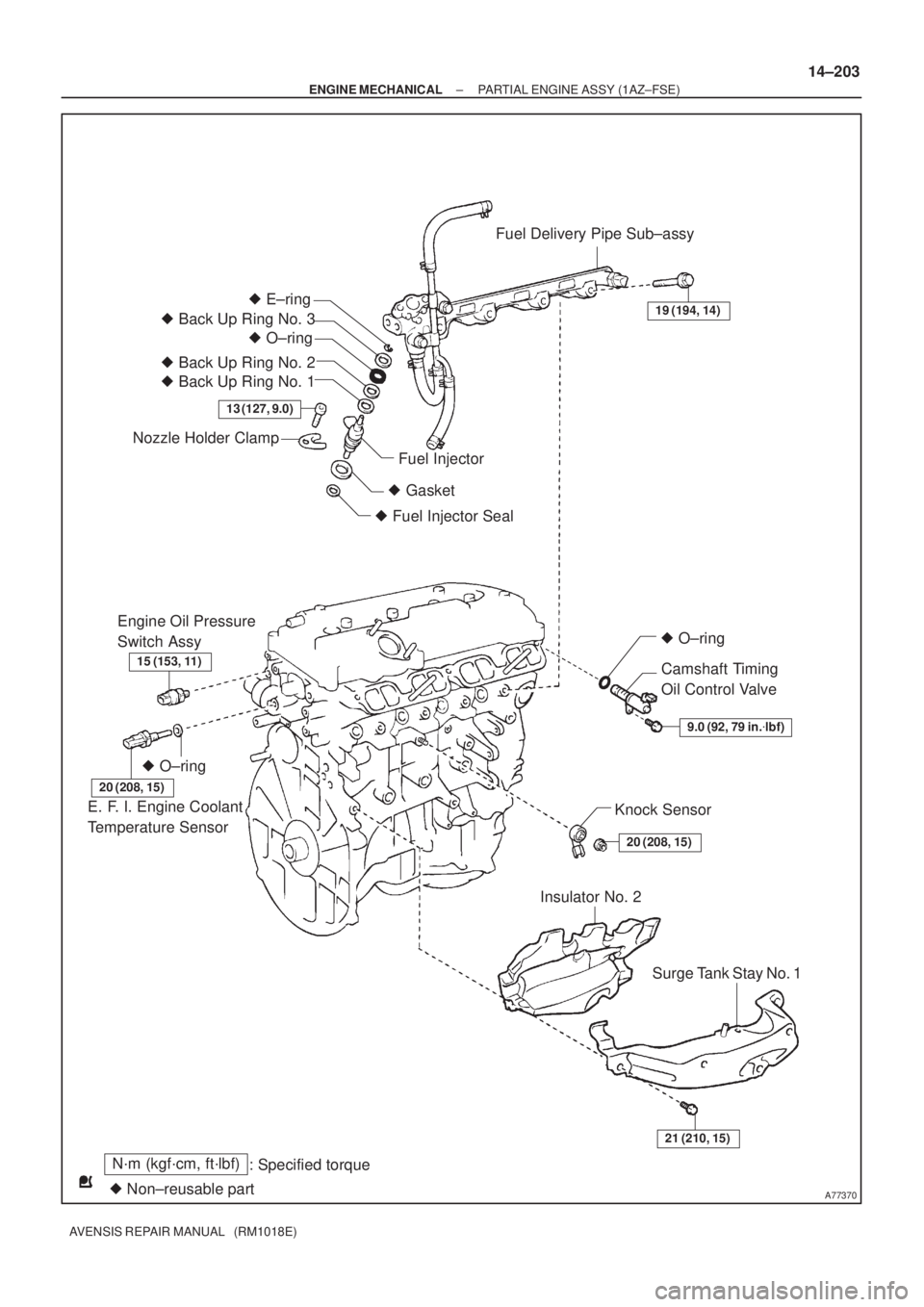
A77370
N´m (kgf´cm, ft´lbf)
: Specified torque
� Non±reusable part� O±ring
13 (127, 9.0)
� E±ring
� O±ring
Nozzle Holder Clamp
Fuel Injector
� Gasket
� Fuel Injector Seal
Fuel Delivery Pipe Sub±assy
19 (194, 14)
Camshaft Timing
Oil Control Valve
� O±ring
20 (208, 15)
Knock Sensor
Insulator No. 2
15 (153, 11)
Engine Oil Pressure
Switch Assy
20 (208, 15)
E. F. I. Engine Coolant
Temperature Sensor
Surge Tank Stay No. 1
9.0 (92, 79 in.�lbf)
21 (210, 15)
� Back Up Ring No. 3
� Back Up Ring No. 2
� Back Up Ring No. 1
± ENGINE MECHANICALPARTIAL ENGINE ASSY (1AZ±FSE)
14±203
AVENSIS REPAIR MANUAL (RM1018E)
Page 2226 of 5135

AVENSIS REPAIR MANUAL (RM1018E)
VALVE CLEARANCE(1AZ±FSE)
ADJUSTMENT
1.DISCHARGE")
141BL±01
A77339
A77343
No. 1 Cylinder TDC / CompressionIN
EX
14±186
±
ENGINE MECHANICAL VALVE CLEARANCE(1AZ±FSE)
AVENSIS REPAIR MANUAL (RM1018E)
VALVE CLEARANCE(1AZ±FSE)
ADJUSTMENT
1.DISCHARGE FUEL SYSTEM PRESSURE (See page 11±33)
2.REMOVE RADIATOR SUPPORT OPENING COVER
3.REMOVE ENGINE ROOM COVER SIDE
4.REMOVE ENGINE UNDER COVER RH 5.REMOVE ENGINE COVER SUB±ASSY NO.1
(a)Remove the 2 nuts and the engine cover No. 1.
6.REMOVE FUEL PRESSURE PULSATION DAMPER ASSY
7.REMOVE FUEL TUBE SUB±ASSY (See page 11±33)
8.REMOVE FUEL PIPE SUB±ASSY NO.1 (See page 11±52) SST 09023±12900
9. REMOVE IGNITION COIL ASSY
(a) Remove the 4 bolts and the ignition coils.
10.REMOVE CYLINDER HEAD COVER SUB±ASSY (See page 14±240)
11.SET NO. 1 CYLINDER TO TDC/COMPRESSION (See page 14±240)
12. INSPECT VALVE CLEARANCE
HINT:
Inspect and adjust the valve clearance when the engine is cold.
(a) Check only the valve indicated in the illustration.(1) Using a feeler gauge, measure the clearance be-tween the valve lifter and the camshaft.
(2) Record the out±of specification valve clearance measurements. They will be used later to determine
the required replacement adjusting shim.
Valve clearance (Cold):
Intake 0.19 to 0.29 mm (0.0075 to 0.0114 in.)
Exhaust 0.30 to 0.40 mm (0.0118 to 0.0157 in.)
(b) Turn the crankshaft clockwise 1 revolution (360 �) and set
No. 4 cylinder to TDC/compression.
Page 2231 of 5135
±
ENGINE MECHANICAL VALVE CLEARANCE(1AZ±FSE)
14±191
AVENSIS REPAIR MANUAL (RM1018E)
(h)Install the camshafts. (See page 14±240)
(i)Install the chain tensioner. (See page 14±240)
14.INSTALL CYLINDER HEAD COVER SUB±ASSY (See page 14±240)
15.INSTALL IGNITION COIL ASSY
Torque: 9.0 N �m (92 kgf �cm,80 in. �lbf)
16.INSTALL FUEL PIPE SUB±ASSY NO.1 (See page 11±52) SST09023±12900
17.INSTALL FUEL TUBE SUB±ASSY (See page 11±33)
18.INSTALL FUEL PRESSURE PULSATION DAMPER ASSY (See page 11±52)
19.CHECK FOR ENGINE OIL LEAKS
20.CHECK FOR FUEL LEAKS (
See page 11±33)
21. INSTALL ENGINE COVER SUB±ASSY NO.1 Torque: 7.0 N �m (71 kgf �cm, 62 in. �lbf)
Page 2252 of 5135

AVENSIS REPAIR MANUAL (RM1018E)
(2) Connect SST (compression gauge) to the SST (at-
tachment).
SST 09992±00025 (09992±")
A61174
SST
Compression Gauge
14±268
± ENGINE MECHANICALENGINE (1CD±FTV)
AVENSIS REPAIR MANUAL (RM1018E)
(2) Connect SST (compression gauge) to the SST (at-
tachment).
SST 09992±00025 (09992±00211)
(3) Fully open the throttle valve, and start the engine.
(4) While cranking the engine, measure the compres-
sion pressure.
NOTICE:
�Always use a fully charged battery to obtain engine
speed of 250 rpm or more.
�Check other cylinder compression pressure in the
same way.
�This measurement must be done in as short a time as
possible.
Compression pressure:
2,628 kPa (26.8 kgf/cm
2, 381 psi) or more
Minimum pressure:
2,157 kPa (22.0 kgf/cm
2, 312 psi) or more
Difference between each cylinder:
490 kPa (5.0 kgf/cm
2, 71 psi) or less
(5) If the cylinder compression is low, pour a small
amount of engine oil into the cylinder through the
glow plug hole and inspect again.
HINT:
�If adding oil raises the compression, there are chances of
the piston rings and/or cylinder bore wear or damage.
�If pressure stays low, a valve may be sticking or seating
improperly, or there may be leakage past the gasket.

14±191
AVENSIS REPAIR MANUAL (RM1018E)
(h)Install the camshafts. (See page 14±240)
(i)Install the chain tensioner. (See page 14±240)
14.INSTALL CYLI")