Page 2868 of 5135

51±26
±
POWER STEERING VANE PUMP ASSY (1CD±FTV)
AVENSIS REPAIR MANUAL (RM1018E)
28. INSTALL FLOW CONTROL VALVE ASSY
(a) Coat the compressi")
������D30361
D30580
B
B
B
A
D30581
Fulcrum
Length
SST(s)
51±26
±
POWER STEERING VANE PUMP ASSY (1CD±FTV)
AVENSIS REPAIR MANUAL (RM1018E)
28. INSTALL FLOW CONTROL VALVE ASSY
(a) Coat the compression spring and the flow control valve assy with power steering fluid.
(b) Install the compression spring and the flow control valve assy.
(c) Coat a new O±ring with power steering fluid and install it onto the pressure port union sub±assy.
(d) Install the pressure port union sub±assy. Torque: 69 N �m (704 kgf �cm, 51 ft �lbf)
29. INSTALL POWER STEERING SUCTION PORT UNION
(a) Coat a new O±ring with power steering fluid, and install it to the su\
ction port union.
(b) Install the suction port union with the bolt. Torque: 12 N �m (122 kgf �cm, 9 ft �lbf)
30. INSTALL VANE PUMP ASSY
(a) Install the vane pump assy and vane pump bracket rear with the 4 bolts.
Torque:
Bolt A: 72 N �m (734 kgf �cm, 53 ft �lbf)
Bolt B: 39 N �m (398 kgf �cm, 29 ft �lbf)
31. CONNECT PRESSURE FEED TUBE ASSY
(a) Using SST(s), connect the pressure feed tube assy. SST 09023±12700
Torque: 41 N �m (414 kgf �cm, 30 ft �lbf)
HINT:
�Use a torque wrench with a fulcrum length of 345 mm
(13.58 in.).
�This torque value is effective when SST(s) is parallel to a
torque wrench.
(b) Install the tube clamp with the bolt. Torque: 8.0 N �m (82 kgf �cm, 71 in. �lbf)
32. CONNECT OIL RESERVOIR TO PUMP HOSE NO.1
(a) Connect the oil reservoir to pump hose No. 1 with the clip.
NOTICE:
Take care not to spill fluid on the V belt.
33. INSTALL V (COOLER COMPRESSOR TO CRANKSHAFT PULLEY) BELT NO.1 (See page 55±46)
34. ADJUST V (COOLER COMPRESSOR TO CRANKSHAFT PULLEY) BELT NO.1
(See page 55±46)
35.ADD POWER STEERING FLUID (See page 51±4)
36.BLEED POWER STEERING FLUID (See page 51±4)
37.CHECK POWER STEERING FULUID LEVEL IN RESERVER (See page 51±4)
38. INSPECT FLUID LEAK
Page 2869 of 5135
5106Z±04
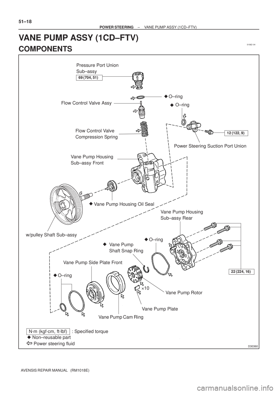
D30360
�
12 (122, 9)Flow Control Valve
Compression Spring
Power Steering Suction Port Union
Vane Pump Housing Oil Seal �
Vane Pump
Shaft Snap Ring
Vane Pump Side Plate Front
Vane Pump Rotor
Vane Pump Plate
Vane Pump Cam Ring
N�m (kgf�cm, ft�lbf) : Specified torque
� Non±reusable part
Power steering fluid
�
�
�
22 (224, 16)
�10
Pressure Port Union
Sub±assy
Flow Control Valve Assy
Vane Pump Housing
Sub±assy Front
�
Vane Pump Housing
Sub±assy Rear
69 (704, 51)
O±ring
O±ring
O±ring
O±ring w/pulley Shaft Sub±assy
51±18
± POWER STEERINGVANE PUMP ASSY (1CD±FTV)
AVENSIS REPAIR MANUAL (RM1018E)
VANE PUMP ASSY (1CD±FTV)
COMPONENTS
Page 2870 of 5135

A
B
F40247
SST(s)
±
POWER STEERING VANE PUMP ASSY (AZ Series)
51±9
AVENSIS REPAIR MANUAL (RM1018E)
OVERHAUL
NOTICE:
�When using a vise, do not over tighten")
510DG±02
F40529
Turn
Hold
D30330
SST(s)
A
B
F40247
SST(s)
±
POWER STEERING VANE PUMP ASSY (AZ Series)
51±9
AVENSIS REPAIR MANUAL (RM1018E)
OVERHAUL
NOTICE:
�When using a vise, do not over tighten.
�When installing, coat the parts indicated by the arrows with power steer\
ing fluid
(See page 51±8).
1. REMOVE FRONT WHEEL RH
2. REMOVE ENGINE UNDER COVER RH
3. REMOVE FAN AND GENERATOR V BELT 1AZ±FE: (See page 14±105)
1AZ±FSE: (See page 14±185)
4. DISCONNECT OIL RESERVOIR TO PUMP HOSE NO.1
(a) Remove the clip and disconnect the oil reservoir to pump hose No.1.
NOTICE:
Take care not to spill fluid on the V belt.
5. DISCONNECT PRESSURE FEED TUBE ASSY
(a) Remove the bolt and separate the pressure feed tubeassy from the pump bracket rear.
(b) Using a spanner (27 mm) to hold the pressure port union, remove the union bolt and gasket.
6. REMOVE VANE PUMP ASSY
(a) Disconnect the connector from the oil pressure switch.
(b) Using SST(s) and a deep socket (14 mm), loosen the bolt A.
SST 09249±63010
(c) Remove the bolt B and vane pump assy.
7. FIX VANE PUMP ASSY
(a) Using SST(s), hold the vane pump assy in a vise. SST 09630±00014 (09631±00132)
8. REMOVE PUMP BRACKET REAR
(a) Remove the bolt and vane pump bracket rear.
Page 2871 of 5135

AVENSIS REPAIR MANUAL (RM1018E)
9. REMOVE POWER STEERING SUCTION PORT UNION
(a) Remove the bolt and the suction port union.
(b")
F42475
C84483
C57767
51±10
± POWER STEERINGVANE PUMP ASSY (AZ Series)
AVENSIS REPAIR MANUAL (RM1018E)
9. REMOVE POWER STEERING SUCTION PORT UNION
(a) Remove the bolt and the suction port union.
(b) Remove the O±ring from the suction port union.
10. REMOVE FLOW CONTROL VALVE ASSY
(a) Remove the pressure port union sub±assy.
(b) Remove the O±ring from the pressure port union sub±
assy.
(c) Remove the flow control valve assy and the compression
spring.
11. REMOVE POWER STEERING OIL PRESSURE SWITCH
NOTICE:
If the oil pressure switch is dropped or damaged, replace it with a new one.
12. REMOVE VANE PUMP HOUSING SUB±ASSY REAR
(a) Remove the 4 bolts and housing sub±assy rear from the
housing sub±assy front.
(b) Remove the O±ring from the housing sub±assy rear.
13. REMOVE W/PULLEY SHAFT SUB±ASSY
(a) Using 2 screwdrivers, remove the snap ring from the w/
pulley shaft sub±assy.
(b) Remove the w/pulley shaft sub±assy.
14. REMOVE VANE PUMP ROTOR
(a) Remove the 10 vane pump plates.
(b) Remove the vane pump rotor.
15. REMOVE VANE PUMP CAM RING
Page 2874 of 5135

Oil Seal
������D30334
Vinyl Tape
± POWER STEERINGVANE PUMP ASSY (AZ Series)
51±13
AVENSIS REPAIR MANUAL (RM1018E)
If necessary, replace")
D31004
Inscribed Mark
R08702
Vernier Calipers
F08480
SST(s)
Oil Seal
������D30334
Vinyl Tape
± POWER STEERINGVANE PUMP ASSY (AZ Series)
51±13
AVENSIS REPAIR MANUAL (RM1018E)
If necessary, replace the flow control valve assy with the one
having the same letter as inscribed on the housing sub±assy
front.
Inscribed mark: A, B, C, D, E or F
HINT:
There are 6 different marks for flow control valve assy.
MarkPart number
A44330±05130
B44330±05140
C44330±05150
D44330±05160
E44330±05170
F44330±05180
21. INSPECT FLOW CONTROL VALVE COMPRESSION
SPRING
(a) Using vernier calipers, measure the free length of the
compression spring.
Minimum free length: 36.9 mm ( 1.453 in.)
If it is less than the minimum, replace the compression spring.
22. INSPECT PRESSURE PORT UNION SUB±ASSY
(a) If the union seat in the pressure port union sub±assy is remarkably damaged, it may cause fluid leak-
age. Replace the pressure port union sub±assy.
23. INSTALL VANE PUMP HOUSING OIL SEAL
(a) Coat a new housing oil seal lip with power steering fluid.
(b) Using SST(s) and a press, install a new housing oil seal.
SST 09950±60010 (09951±00280), 09950±70010
(09951±07100)
NOTICE:
Make sure that the oil seal is installed facing in the correct
direction.
24. INSTALL W/PULLEY SHAFT SUB±ASSY
(a) Coat inside bushing surface of the housing sub±assy
front with power steering fluid.
(b) Gradually insert the w/pulley shaft sub±assy.
NOTICE:
Do not damage the oil seal lip.
HINT:
Tape the shaft before inserting.
Page 2876 of 5135

51±15
AVENSIS REPAIR MANUAL (RM1018E)
(b) Coat 10 vane pump plates with power steerin")
������D30335
Inward
Outward
������D30336
C70126
C53369
Service Bolt
± POWER STEERINGVANE PUMP ASSY (AZ Series)
51±15
AVENSIS REPAIR MANUAL (RM1018E)
(b) Coat 10 vane pump plates with power steering fluid.
(c) Install the vane pump plates with the round end facing
outward.
28. INSTALL VANE PUMP SHAFT SNAP RING
(a) Using a screwdriver and a snap ring expander, install a
new snap ring to the w/pulley shaft sub±assy.
29. INSTALL VANE PUMP HOUSING SUB±ASSY REAR
(a) Coat a new O±ring with power steering fluid and install it
onto the housing sub±assy rear.
(b) Align the straight pin of the housing sub±assy rear with
the dents of the cam ring, side plate front and housing
sub±assy front, and install the vane pump housing sub±
assy rear with the 4 bolts.
Torque: 22 N�m (224 kgf�cm, 16 ft�lbf)
30. INSPECT PRELOAD
(a) Check that the pump rotates smoothly without abnormal
noise.
(b) Temporarily install the service bolt.
Recommended service bolt:
Thread diameter: 10 mm (0.39 in.)
Thread pitch: 1.25 mm (0.0492 in.)
Bolt length: 50 mm (1.97 in.)
(c) Using a torque wrench, check the pump rotating torque.
Rotating torque:
0.27 N�m (2.8 kgf�cm, 2.4 ft�lbf) or less
If the rotating torque is not as specified, check the housing oil
seal.
31. INSTALL POWER STEERING OIL PRESSURE SWITCH
(a) Coat a new O±ring with power steering fluid and install it to the oil pressure switch.
(b) Install the oil pressure switch onto the vane pump assy.
Torque: 21 N�m (214 kgf�cm, 15 ft�lbf)
Page 2877 of 5135

BFulcrum Length
F41596
Pressure Feed
Tube Assy
Stopper
51±16
± POWER STEERINGVANE PUMP ASSY (AZ Series)
AVENSIS REPAIR MANUAL (RM1018E)
32. INSTALL FLOW CONTROL VALVE ASSY")
F42475
F40330
A
SST(s)
BFulcrum Length
F41596
Pressure Feed
Tube Assy
Stopper
51±16
± POWER STEERINGVANE PUMP ASSY (AZ Series)
AVENSIS REPAIR MANUAL (RM1018E)
32. INSTALL FLOW CONTROL VALVE ASSY
(a) Coat the compression spring and the flow control valve
assy with power steering fluid.
(b) Install the compression spring and the flow control valve
assy.
(c) Coat a new O±ring with power steering fluid and install it
onto the pressure port union sub±assy.
(d) Install the pressure port union sub±assy.
Torque: 69 N�m (704 kgf�cm, 51 ft�lbf)
33. INSTALL POWER STEERING SUCTION PORT UNION
(a) Coat a new O±ring with power steering fluid, and install it to the suction port union.
(b) Install the suction port union with the bolt.
Torque: 12 N�m (122 kgf�cm, 9 ft�lbf)
34. INSTALL PUMP BRACKET REAR
(a) Install the vane pump bracket rear with the bolt.
Torque: 44 N�m (449 kgf�cm, 32 ft�lbf)
HINT:
Make sure that the stopper of the bracket touches the vane pump body, then torque the bolt.
35. INSTALL VANE PUMP ASSY
(a) Temporarily tighten the bolt A to the vane pump assy.
(b) Install the vane pump assy and the bolt B.
Torque: 37 N�m (377 kgf�cm, 27 ft�lbf)
(c) Using SST(s) and a deep socket (14 mm), tighten the bolt
A.
SST 09249±63010
Torque: 26 N�m (264 kgf�cm, 19 ft�lbf)
HINT:
�Use a torque wrench with a fulcrum length of 345 mm
(13.58 in.).
�This torque value is effective when SST(s) is parallel to a
torque wrench.
(d) Connect the connector to the oil pressure switch.
36. CONNECT PRESSURE FEED TUBE ASSY
(a) Install the pressure feed tube assy and gasket to the vane
pump assy with the union bolt.
HINT:
Make sure the stopper of the pressure feed tube assy touches
the pump housing front as shown in the illustration.
(b) Using a spanner (27 mm) to hold the pressure port union,
torque the union bolt.
Torque: 52 N�m (525 kgf�cm, 38 ft�lbf)
(c) Install the pressure feed tube assy with bolt to the pump
bracket rear.
Torque: 8.0 N�m (82 kgf�cm, 71 in.�lbf)
Page 2879 of 5135
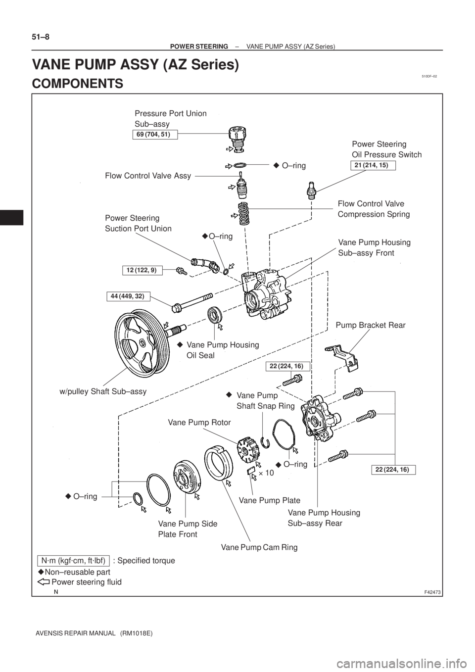
510DF±02
F42473
Power Steering
Suction Port Union
O±ring �
w/pulley Shaft Sub±assy
Vane Pump Side
Plate Front
Vane Pump Cam Ring�10
�
N�m (kgf�cm, ft�lbf) : Specified torque
Non±reusable part �
Power steering fluid
Pump Bracket Rear
Flow Control Valve Assy
�
Flow Control Valve
Compression Spring
44 (449, 32)
Vane Pump Housing
Sub±assy RearVane Pump Housing
Sub±assy Front
�
Vane Pump Rotor
Vane Pump Plate
22 (224, 16)
Vane Pump Housing
Oil Seal �
Power Steering
Oil Pressure Switch
21 (214, 15)
69 (704, 51)
Vane Pump
Shaft Snap Ring �O±ring
O±ring
O±ring
22 (224, 16)
Pressure Port Union
Sub±assy
12 (122, 9)
51±8
± POWER STEERINGVANE PUMP ASSY (AZ Series)
AVENSIS REPAIR MANUAL (RM1018E)
VANE PUMP ASSY (AZ Series)
COMPONENTS