Page 3434 of 5135
B67164
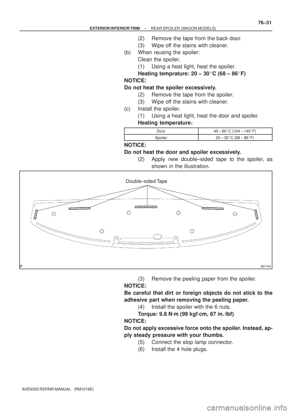
Double±sided Tape
± EXTERIOR/INTERIOR TRIMREAR SPOILER (WAGON MODELS)
76±31
AVENSIS REPAIR MANUAL (RM1018E)
(2) Remove the tape from the back door.
(3) Wipe off the stains with cleaner.
(b) When reusing the spoiler:
Clean the spoiler.
(1) Using a heat light, heat the spoiler.
Heating temprature: 20 ± 30�C (68 ± 86�F)
NOTICE:
Do not heat the spoiler excessively.
(2) Remove the tape from the spoiler.
(3) Wipe off the stains with cleaner.
(c) Install the spoiler.
(1) Using a heat light, heat the door and spoiler.
Heating temperature:
Door40 ± 60�C (104 ± 140�F)
Spoiler20 ± 30�C (68 ± 86�F)
NOTICE:
Do not heat the door and spoiler excessively.
(2) Apply new double±sided tape to the spoiler, as
shown in the illustration.
(3) Remove the peeling paper from the spoiler.
NOTICE:
Be careful that dirt or foreign objects do not stick to the
adhesive part when removing the peeling paper.
(4) Install the spoiler with the 6 nuts.
Torque: 9.8 N�m (99 kgf�cm, 87 in.�lbf)
NOTICE:
Do not apply excessive force onto the spoiler. Instead, ap-
ply steady pressure with your thumbs.
(5) Connect the stop lamp connector.
(6) Install the 4 hole plugs.
Page 3609 of 5135
C68212
D25110
C68213
C67875
C67876
40±60
± AUTOMATIC TRANSMISSION / TRANSINTERMEDIATE SHAFT ASSY (U34#E Series)
U340E A/T REPAIR MANUAL (RM824E)
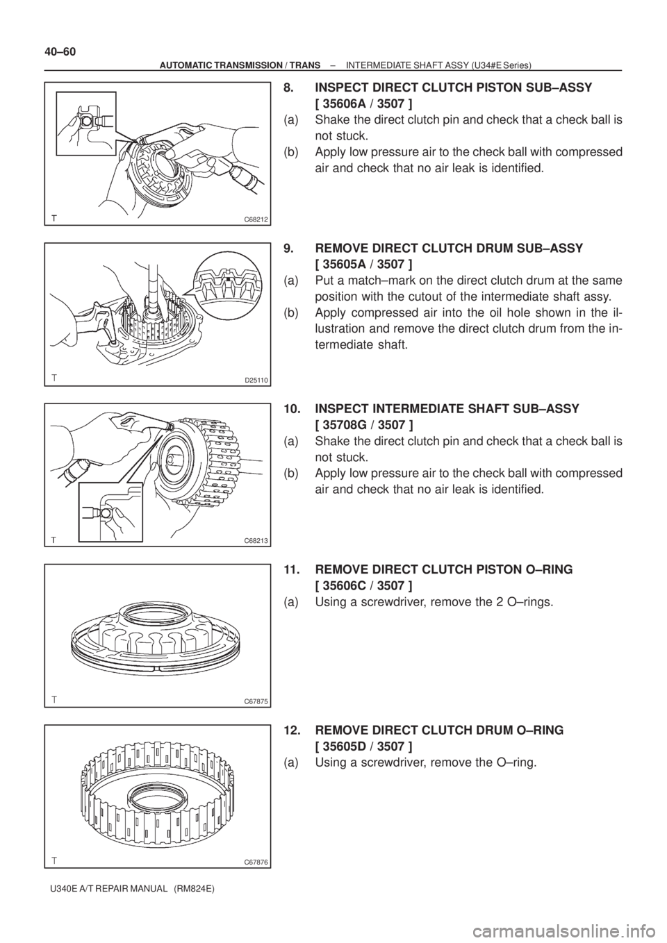
8. INSPECT DIRECT CLUTCH PISTON SUB±ASSY
[ 35606A / 3507 ]
(a) Shake the direct clutch pin and check that a check ball is
not stuck.
(b) Apply low pressure air to the check ball with compressed
air and check that no air leak is identified.
9. REMOVE DIRECT CLUTCH DRUM SUB±ASSY
[ 35605A / 3507 ]
(a) Put a match±mark on the direct clutch drum at the same
position with the cutout of the intermediate shaft assy.
(b) Apply compressed air into the oil hole shown in the il-
lustration and remove the direct clutch drum from the in-
termediate shaft.
10. INSPECT INTERMEDIATE SHAFT SUB±ASSY
[ 35708G / 3507 ]
(a) Shake the direct clutch pin and check that a check ball is
not stuck.
(b) Apply low pressure air to the check ball with compressed
air and check that no air leak is identified.
11. REMOVE DIRECT CLUTCH PISTON O±RING
[ 35606C / 3507 ]
(a) Using a screwdriver, remove the 2 O±rings.
12. REMOVE DIRECT CLUTCH DRUM O±RING
[ 35605D / 3507 ]
(a) Using a screwdriver, remove the O±ring.
Page 3681 of 5135
D03807
SST
D03630Seal Bend Width 1.2 mm (0.047 in.) FIPG
C50259
C
C
C
CA
AA B
BB
C83145
± AUTOMATIC TRANSMISSION / TRANSAUTOMATIC TRANSAXLE ASSY (U241E)
40±59
U241E A/T REPAIR MANUAL (RM840U)
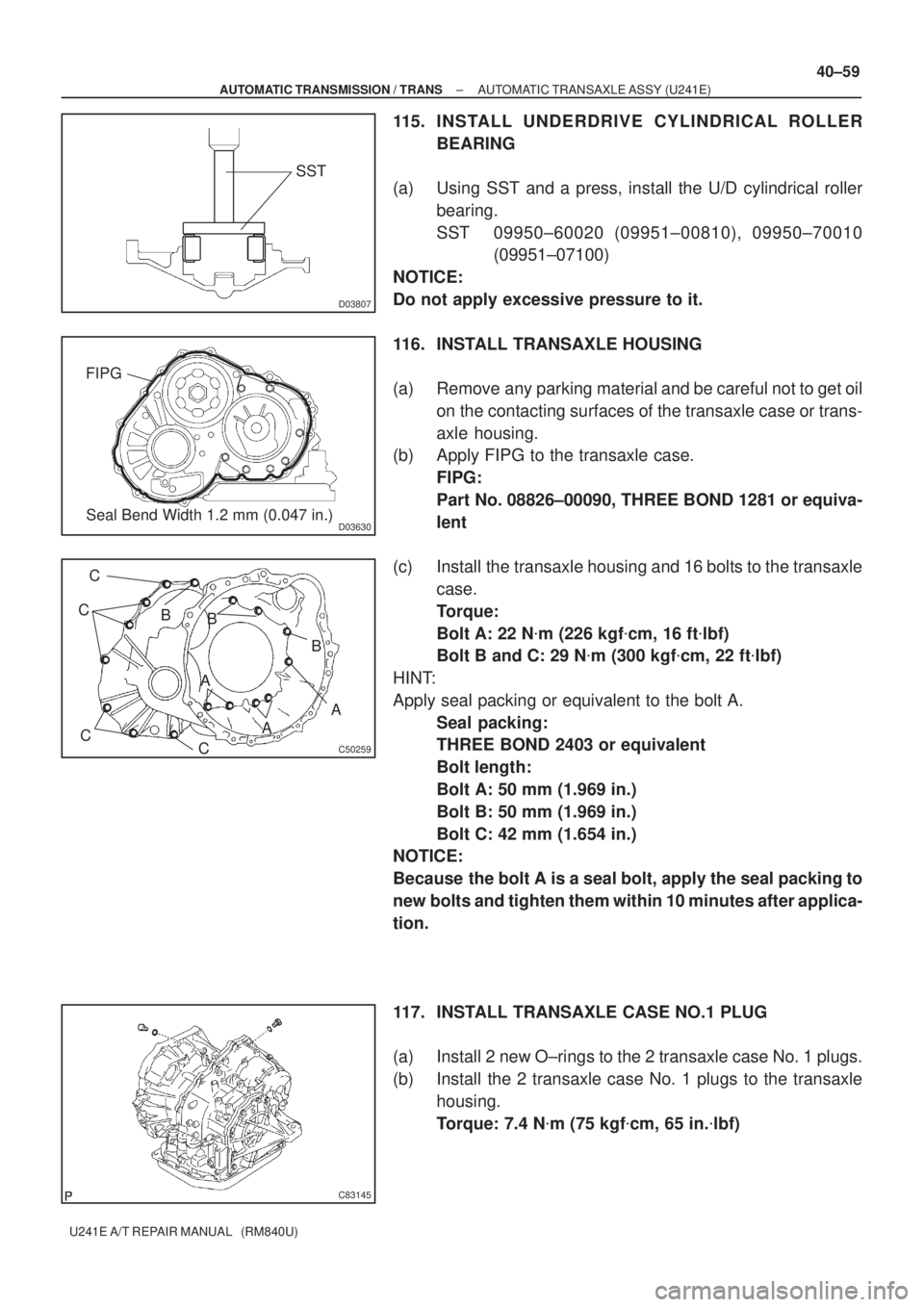
115. INSTALL UNDERDRIVE CYLINDRICAL ROLLER
BEARING
(a) Using SST and a press, install the U/D cylindrical roller
bearing.
SST 09950±60020 (09951±00810), 09950±70010
(09951±07100)
NOTICE:
Do not apply excessive pressure to it.
116. INSTALL TRANSAXLE HOUSING
(a) Remove any parking material and be careful not to get oil
on the contacting surfaces of the transaxle case or trans-
axle housing.
(b) Apply FIPG to the transaxle case.
FIPG:
Part No. 08826±00090, THREE BOND 1281 or equiva-
lent
(c) Install the transaxle housing and 16 bolts to the transaxle
case.
Torque:
Bolt A: 22 N�m (226 kgf�cm, 16 ft�lbf)
Bolt B and C: 29 N�m (300 kgf�cm, 22 ft�lbf)
HINT:
Apply seal packing or equivalent to the bolt A.
Seal packing:
THREE BOND 2403 or equivalent
Bolt length:
Bolt A: 50 mm (1.969 in.)
Bolt B: 50 mm (1.969 in.)
Bolt C: 42 mm (1.654 in.)
NOTICE:
Because the bolt A is a seal bolt, apply the seal packing to
new bolts and tighten them within 10 minutes after applica-
tion.
117. INSTALL TRANSAXLE CASE NO.1 PLUG
(a) Install 2 new O±rings to the 2 transaxle case No. 1 plugs.
(b) Install the 2 transaxle case No. 1 plugs to the transaxle
housing.
Torque: 7.4 N�m (75 kgf�cm, 65 in.�lbf)
Page 3784 of 5135
A62191
Advanced
Side Path Retard
Side Path
A62192
Hold Pressure
DecompressAdvanced
Side Path Retard
Side Path
± ENGINE MECHANICALPARTIAL ENGINE ASSY (1ZZ±FE/3ZZ±FE)
14±7
1ZZ±FE,3ZZ±FE ENGINE REPAIR MANUAL
(RM923E)
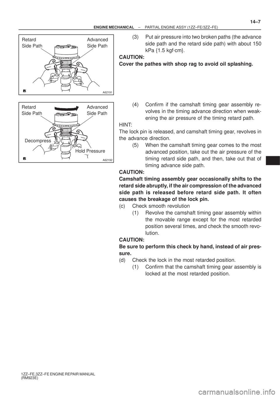
(3) Put air pressure into two broken paths (the advance
side path and the retard side path) with about 150
kPa {1.5 kgf�cm}.
CAUTION:
Cover the pathes with shop rag to avoid oil splashing.
(4) Confirm if the camshaft timing gear assembly re-
volves in the timing advance direction when weak-
ening the air pressure of the timing retard path.
HINT:
The lock pin is released, and camshaft timing gear, revolves in
the advance direction.
(5) When the camshaft timing gear comes to the most
advanced position, take out the air pressure of the
timing retard side path, and then, take out that of
timing advance side path.
CAUTION:
Camshaft timing assembly gear occasionally shifts to the
retard side abruptly, if the air compression of the advanced
side path is released before retard side path. It often
causes the breakage of the lock pin.
(c) Check smooth revolution
(1) Revolve the camshaft timing gear assembly within
the movable range except for the most retarded
position several times, and check the smooth revo-
lution.
CAUTION:
Be sure to perform this check by hand, instead of air pres-
sure.
(d) Check the lock in the most retarded position.
(1) Confirm that the camshaft timing gear assembly is
locked at the most retarded position.
Page 3785 of 5135
A62190
Advance
Side Path Retard Side
Path
Open
Close
Rubber Vinyl Tape Open Close
A62191
Advanced
Side Path Retard
Side Path
A62192
Hold Pressure
DecompressAdvanced
Side Path Retard
Side Path
14±8
± ENGINE MECHANICALPARTIAL ENGINE ASSY (1ZZ±FE/3ZZ±FE)
1ZZ±FE,3ZZ±FE ENGINE REPAIR MANUAL
(RM923E)
19. REMOVE CAMSHAFT TIMING GEAR ASSY
(a) Grip the camshaft with a vice, and confirm that the gear
is locked.
CAUTION:
Be careful not to damage the camshaft.
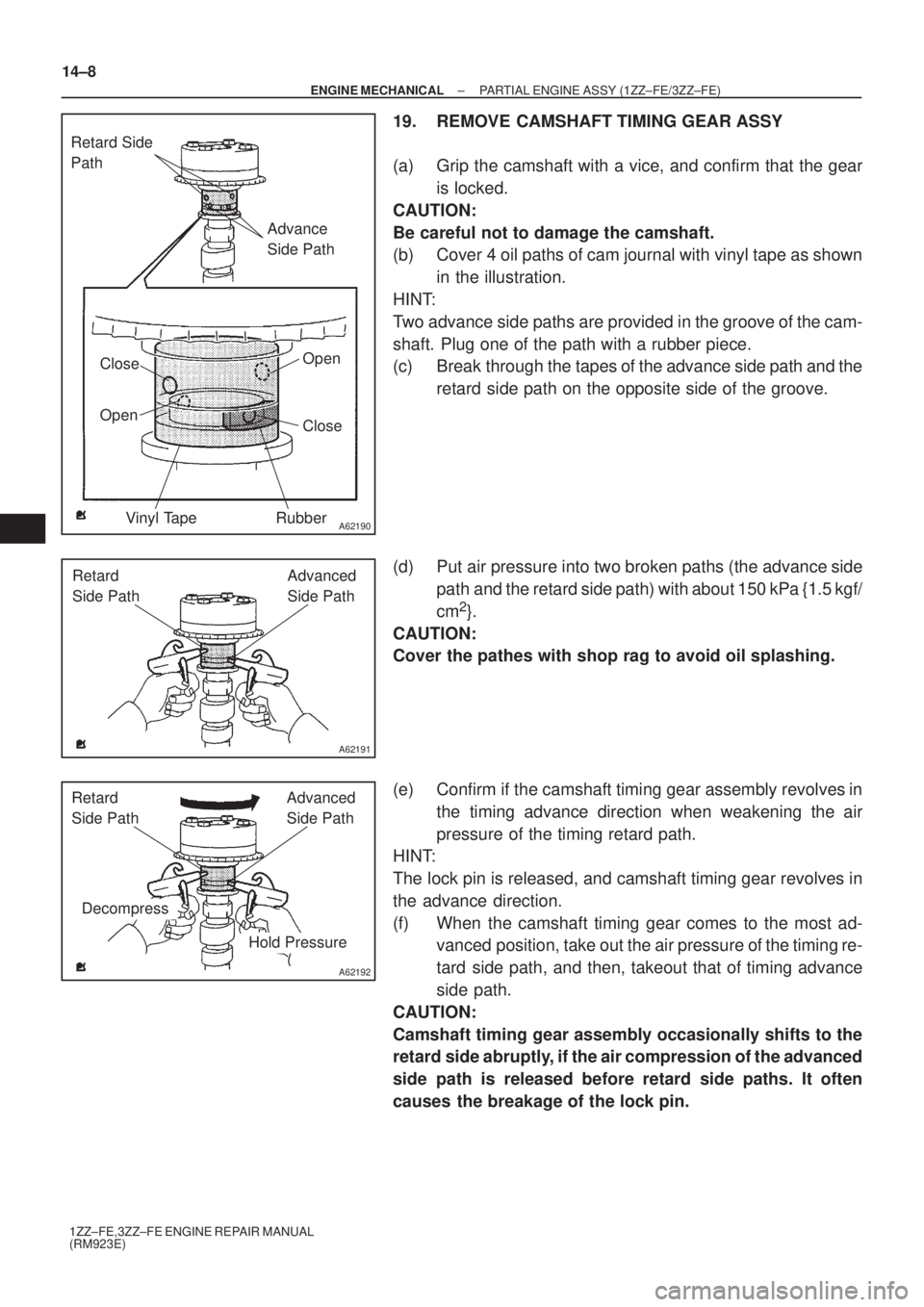
(b) Cover 4 oil paths of cam journal with vinyl tape as shown
in the illustration.
HINT:
Two advance side paths are provided in the groove of the cam-
shaft. Plug one of the path with a rubber piece.
(c) Break through the tapes of the advance side path and the
retard side path on the opposite side of the groove.
(d) Put air pressure into two broken paths (the advance side
path and the retard side path) with about 150 kPa {1.5 kgf/
cm
2}.
CAUTION:
Cover the pathes with shop rag to avoid oil splashing.
(e) Confirm if the camshaft timing gear assembly revolves in
the timing advance direction when weakening the air
pressure of the timing retard path.
HINT:
The lock pin is released, and camshaft timing gear revolves in
the advance direction.
(f) When the camshaft timing gear comes to the most ad-
vanced position, take out the air pressure of the timing re-
tard side path, and then, takeout that of timing advance
side path.
CAUTION:
Camshaft timing gear assembly occasionally shifts to the
retard side abruptly, if the air compression of the advanced
side path is released before retard side paths. It often
causes the breakage of the lock pin.
Page 3849 of 5135
A56697
A56698
A56699
A09518
A09519
Hexagon
Wrench
(8mm)
± ENGINE MECHANICALPARTIAL ENGINE ASSY (1CD±FTV)
14±7
1CD±FTV ENGINE REPAIR MANUAL (RM927E)
18. REMOVE OIL PAN SUB±ASSY
(a) Remove the 19 bolts and 3 nuts.
(b) Using a screwdriver, remove the oil pan by prying the por-
tions between the cylinder block and No. 1 oil pan.
NOTICE:
Be careful not to damage the contact surfaces of the cylin-
der block and No. 1 oil pan.
19. REMOVE OIL PUMP ASSY
(a) Remove the 9 bolts.
(b) Remove the oil pump by prying a screwdriver between the
oil pump and main bearing cap.
(c) Remove the gasket.
20. REMOVE ENGINE REAR OIL SEAL RETAINER
(a) Remove the 6 bolts.
(b) Using a screwdriver, remove the oil seal retainer by prying
the portions between the oil seal retainer and main bear-
ing cap.
21. REMOVE OIL CHECK VALVE SUB±ASSY
(a) Using hexagon wrench (8mm), remove the pressure
valve and gasket.
Page 3852 of 5135
A09519
Hexagon
Wrench
(8mm)
A09476
Seal Width
2 ± 3 mm
A56701
Seal Width
2 ± 4 mm
Seal
PackingNew Gasket
14±10
± ENGINE MECHANICALPARTIAL ENGINE ASSY (1CD±FTV)
1CD±FTV ENGINE REPAIR MANUAL (RM927E)
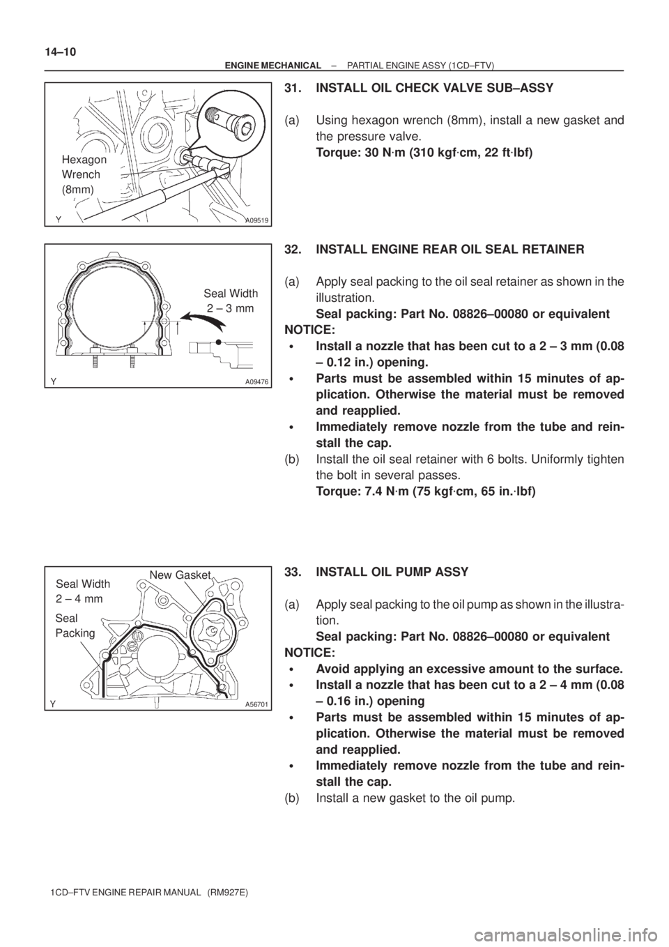
31. INSTALL OIL CHECK VALVE SUB±ASSY
(a) Using hexagon wrench (8mm), install a new gasket and
the pressure valve.
Torque: 30 N�m (310 kgf�cm, 22 ft�lbf)
32. INSTALL ENGINE REAR OIL SEAL RETAINER
(a) Apply seal packing to the oil seal retainer as shown in the
illustration.
Seal packing: Part No. 08826±00080 or equivalent
NOTICE:
�Install a nozzle that has been cut to a 2 ± 3 mm (0.08
± 0.12 in.) opening.
�Parts must be assembled within 15 minutes of ap-
plication. Otherwise the material must be removed
and reapplied.
�Immediately remove nozzle from the tube and rein-
stall the cap.
(b) Install the oil seal retainer with 6 bolts. Uniformly tighten
the bolt in several passes.
Torque: 7.4 N�m (75 kgf�cm, 65 in.�lbf)
33. INSTALL OIL PUMP ASSY
(a) Apply seal packing to the oil pump as shown in the illustra-
tion.
Seal packing: Part No. 08826±00080 or equivalent
NOTICE:
�Avoid applying an excessive amount to the surface.
�Install a nozzle that has been cut to a 2 ± 4 mm (0.08
± 0.16 in.) opening
�Parts must be assembled within 15 minutes of ap-
plication. Otherwise the material must be removed
and reapplied.
�Immediately remove nozzle from the tube and rein-
stall the cap.
(b) Install a new gasket to the oil pump.
Page 3937 of 5135
A78640
1.0 to 1.1 mm
(0.039 to 0.043 in.)
±
DIAGNOSTICS SFI SYSTEM(1AZ±FSE)
05±423
AVENSIS REPAIR MANUAL (RM1018E)
5CHECK SPARK PLUG AND SPARK OF MISFIRING CYLINDER
(a)Remove the ignition coil with igniter assy.
(b)Remove the spark plug.
(c)Check the spark plug type.
Recommended spark plug:
DENSO madeSK20BR11
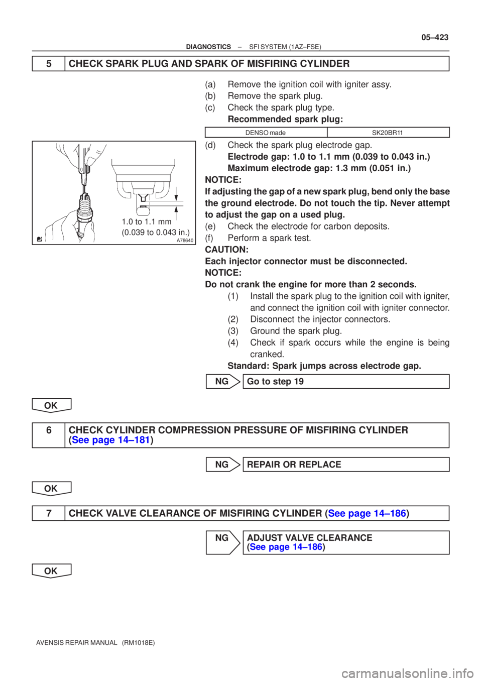
(d)Check the spark plug electrode gap.Electrode gap: 1.0 to 1.1 mm (0.039 to 0.043 in.)
Maximum electrode gap: 1.3 mm (0.051 in.)
NOTICE:
If adjusting the gap of a new spark plug, bend only the base
the ground electrode. Do not touch the tip. Never attempt
to adjust the gap on a used plug.
(e)Check the electrode for carbon deposits.
(f)Perform a spark test.
CAUTION:
Each injector connector must be disconnected.
NOTICE:
Do not crank the engine for more than 2 seconds. (1)Install the spark plug to the ignition coil with igniter,and connect the ignition coil with igniter connector.
(2)Disconnect the injector connectors.
(3)Ground the spark plug.
(4)Check if spark occurs while the engine is being
cranked.
Standard: Spark jumps across electrode gap.
NGGo to step 19
OK
6CHECK CYLINDER COMPRESSION PRESSURE OF MISFIRING CYLINDER (See page 14±181)
NGREPAIR OR REPLACE
OK
7CHECK VALVE CLEARANCE OF MISFIRING CYLINDER (See page 14±186)
NG ADJUST VALVE CLEARANCE (See page 14±186)
OK