Page 2135 of 4555
SERVICE DATA AND SPECIFICATIONS (SDS)
ACC-3
C
D
E
F
G
H
I
J
K
L
MA
ACC
SERVICE DATA AND SPECIFICATIONS (SDS)PFP:00030
Tightening TorqueEBS00KP6
Unit: N·m (kg-m, in-lb)
Accelerator pedal assembly 5.1 (0.52, 45)
Page 2139 of 4555
PREPARATION
CL-3
D
E
F
G
H
I
J
K
L
MA
B
CL
PREPARATIONPFP:00002
Special Service ToolsECS008B7
Commercial Service ToolsECS00CRA
Tool number
Tool nameDescription
ST20050240
Diaphragm adjusting wrenchAdjusting unevenness of diaphragm spring of
clutch cover
KV30101600
Clutch aligning bar
a: 15.9 mm (0.626 in) dia.
b: 17.9 mm (0.705 in) dia.
c: 40 mm (1.57 in) dia.Installing clutch cover and clutch disc
(For QR engine models)
KV30100100
Clutch aligning bar
a: 15.7 mm (0.618 in) dia.
b: 22.8 mm (0.898 in) dia.Installing clutch cover and clutch disc
(For YD engine models)
ZZA0508D
S-NT405
ZZA1178D
Tool nameDescription
Pin punch
Tip diameter: 4.5 mm (0.177 in) dia.Removing and installing master cylinder
spring pin
GG94310000
Flare nut torque wrench
a: 10 mm (0.39 in)Removing and installing clutch piping
ZZA0515D
S-NT406
Page 2143 of 4555
CLUTCH PEDAL
CL-7
D
E
F
G
H
I
J
K
L
MA
B
CL
4. Remove clutch pedal assembly mounting nuts and bolt, and then remove clutch pedal assembly from the
vehicle.
INSPECTION AFTER REMOVAL
�Check clutch pedal for bend, damage or a cracked weld. If bend, damage or a cracked weld is found,
replace clutch pedal.
�Check assist spring for settling. If settling is found, replace assist spring.
INSTALLATION
Installation is the reverse order of removal.
NOTE:
Tighten pedal stopper bolt lock nut or ASCD clutch switch lock nut to the specified torque after installing clutch
pedal assembly in vehicle and adjusting the pedal free play.
Page 2144 of 4555

CL-8
CLUTCH FLUID
CLUTCH FLUIDPFP:00017
Air Bleeding ProcedureECS008B9
NOTE:
Do not use a vacuum assist or any other type of power bleeder on this system. Use of a vacuum assist or
power bleeder will not purge all the air from the system.
CAUTION:
�Monitor clutch fluid level in reservoir tank to make sure it
does not empty.
�Keep painted surface on the body or other parts free of
clutch fluid. If it spills, wipe up immediately and wash the
affected area with water.
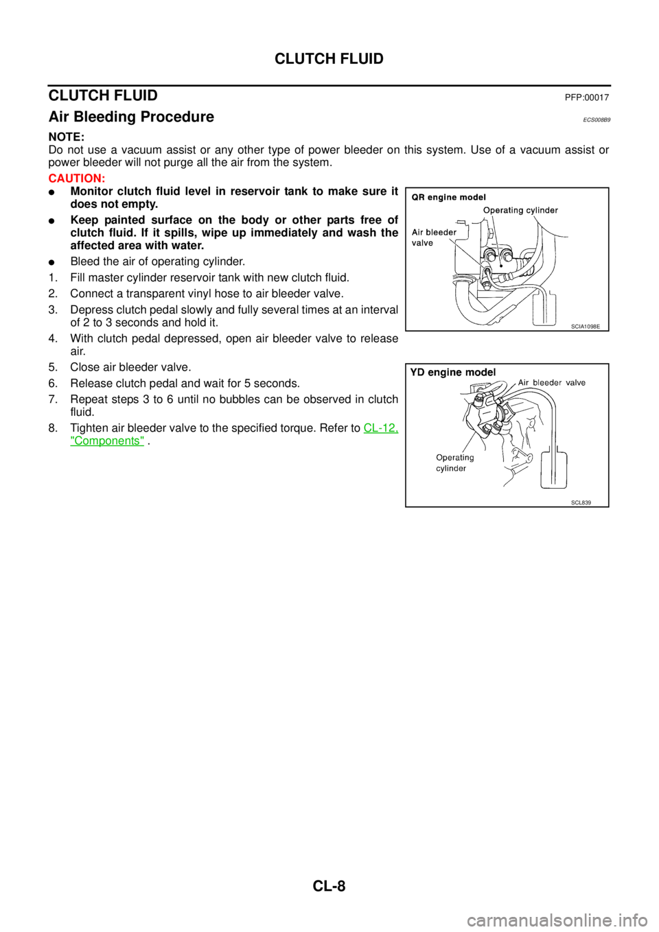
�Bleed the air of operating cylinder.
1. Fill master cylinder reservoir tank with new clutch fluid.
2. Connect a transparent vinyl hose to air bleeder valve.
3. Depress clutch pedal slowly and fully several times at an interval
of 2 to 3 seconds and hold it.
4. With clutch pedal depressed, open air bleeder valve to release
air.
5. Close air bleeder valve.
6. Release clutch pedal and wait for 5 seconds.
7. Repeat steps 3 to 6 until no bubbles can be observed in clutch
fluid.
8. Tighten air bleeder valve to the specified torque. Refer to CL-12,
"Components" .
SCIA1098E
SCL839
Page 2146 of 4555

CL-10
CLUTCH MASTER CYLINDER
Removal and InstallationECS008BA
REMOVAL
1. Using one of the following methods, remove hose from nipple.
�Drain clutch fluid from reservoir tank and remove hose.
�Remove hose from nipple. Immediately plug hose and reservoir tank to prevent clutch fluid from drip-
ping.
CAUTION:
Keep painted surface on the body or other parts free of clutch fluid. If it spills, wipe up immediately
and wash the affected area with water.
2. Remove clutch tube using a flare nut torque wrench.
3. Remove snap pin and clevis pin on clevis in passenger compartment to separate clutch pedal.
4. Remove mounting nuts on master cylinder assembly, and then master cylinder assembly from vehicle.
INSTALLATION
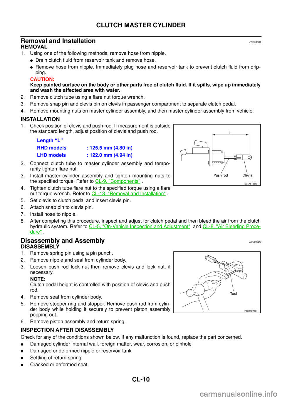
1. Check position of clevis and push rod. If measurement is outside
the standard length, adjust position of clevis and push rod.
2. Connect clutch tube to master cylinder assembly and tempo-
rarily tighten flare nut.
3. Install master cylinder assembly and tighten mounting nuts to
the specified torque. Refer to CL-9, "
Components" .
4. Tighten clutch tube flare nut to the specified torque using a flare
nut torque wrench. Refer to CL-13, "
Removal and Installation" .
5. Set clevis to clutch pedal and insert clevis pin.
6. Attach snap pin to clevis pin.
7. Install hose to nipple.
8. After completing this procedure, inspect and adjust for clutch pedal and then bleed the air from the clutch
hydraulic system. Refer to CL-5, "
On-Vehicle Inspection and Adjustment" and CL-8, "Air Bleeding Proce-
dure" .
Disassembly and AssemblyECS008BB
DISASSEMBLY
1. Remove spring pin using a pin punch.
2. Remove nipple and seal from cylinder body.
3. Loosen push rod lock nut then remove clevis and lock nut, if
necessary.
NOTE:
Clutch pedal height is controlled with position of clevis and push
rod.
4. Remove seat from cylinder body.
5. Remove stopper ring and stopper. Remove push rod from cylin-
der body while holding it securely to prevent piston assembly
popping out.
6. Remove piston assembly and return spring.
INSPECTION AFTER DISASSEMBLY
Check for any of the conditions shown below. If any malfunction is found, replace the part concerned.
�Damaged cylinder internal wall, foreign matter, wear, corrosion, or pinhole
�Damaged or deformed nipple or reservoir tank
�Settling of return spring
�Cracked or deformed seatLength “L”
RHD models : 125.5 mm (4.80 in)
LHD models : 122.0 mm (4.94 in)
SCIA5158E
PCIB0274E
Page 2147 of 4555
CLUTCH MASTER CYLINDER
CL-11
D
E
F
G
H
I
J
K
L
MA
B
CL
ASSEMBLY
1. Apply rubber lubricant to the internal surface of cylinder body, the sliding surface of piston assembly, and
piston cup. Insert return spring and piston assembly to cylinder body.
2. Apply silicon grease to push rod and install stopper. Install stopper ring while holding down push rod by
hand to prevent piston assembly from popping out.
3. Install seat to cylinder body.
4. Install seal and nipple to cylinder body. Install spring pin using a pin punch.
5. Install clevis to push rod.
6. Check and adjust the positions of clevis and push rod. After
adjusting “L”, tighten lock nut to the specified torque. Refer to
CL-9, "
Components" .
Length “L”
RHD models : 125.5 mm (4.80 in)
LHD models : 122.0 mm (4.94 in)
SCIA5158E
Page 2149 of 4555
CLUTCH PIPING
CL-13
D
E
F
G
H
I
J
K
L
MA
B
CL
CLUTCH PIPINGPFP:30650
Removal and InstallationECS008BE
Carefully observe the following steps during clutch tube removal and installation.
CAUTION:
Keep painted surface on the body or other parts free of clutch fluid. If it spills, wipe up immediately
and wash the affected area with water.
�To fix clutch hose on bracket, position clutch hose clasp on the
emboss of bracket and drive lock plate vertically from above. Be
careful not to bend or twist clutch hose. Do not scratch or dam-
age clutch hose.
�Tighten clutch tube flare nut to the specified torque.
�Tighten clutch hose union bolt to the specified torque.
CAUTION:
Do not reuse copper washer.
�After installation, bleed the air from the clutch hydraulic system.
Refer to CL-8, "
Air Bleeding Procedure" .
1. Clutch tube 2. Lock plate 3. Clutch hose
4. Operating cylinder 5. Clutch pedal 6. Master cylinder
PCIB0813E
PCIB0681E
Page 2168 of 4555

MT-12
M/T OIL
M/T OILPFP:KLD20
Changing M/T OilECS008BR
DRAINING
1. Start engine and let it run to warm up transaxle.
2. Stop engine. Remove drain plug and then drain oil.
3. Set a gasket on drain plug and install it to transaxle case. Tighten drain plug to the specified torque. Refer
to MT-22, "
Case and Housing Components" (RS5F51A) or MT-40, "Case and Housing Components"
(RS6F51A).
CAUTION:
Do not reuse gasket.
FILLING
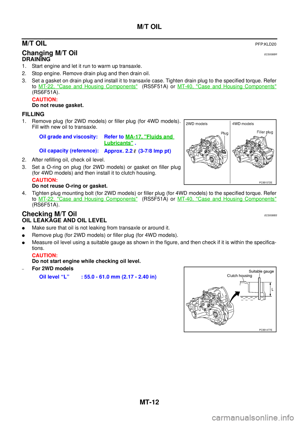
1. Remove plug (for 2WD models) or filler plug (for 4WD models).
Fill with new oil to transaxle.
2. After refilling oil, check oil level.
3. Set a O-ring on plug (for 2WD models) or gasket on filler plug
(for 4WD models) and then install it to clutch housing.
CAUTION:
Do not reuse O-ring or gasket.
4. Tighten plug mounting bolt (for 2WD models) or filler plug (for 4WD models) to the specified torque. Refer
to MT-22, "
Case and Housing Components" (RS5F51A) or MT-40, "Case and Housing Components"
(RS6F51A).
Checking M/T OilECS008BS
OIL LEAKAGE AND OIL LEVEL
�Make sure that oil is not leaking from transaxle or around it.
�Remove plug (for 2WD models) or filler plug (for 4WD models).
�Measure oil level using a suitable gauge as shown in the figure, and then check if it is within the specifica-
tions.
CAUTION:
Do not start engine while checking oil level.
–For 2WD modelsOil grade and viscosity: Refer to MA-17, "
Fluids and
Lubricants" .
Oil capacity (reference):
Approx. 2.2 (3-7/8 lmp pt)
PCIB1572E
Oil level “L” : 55.0 - 61.0 mm (2.17 - 2.40 in)
PCIB1477E