Page 2278 of 4555
AT-14
PREPARATION
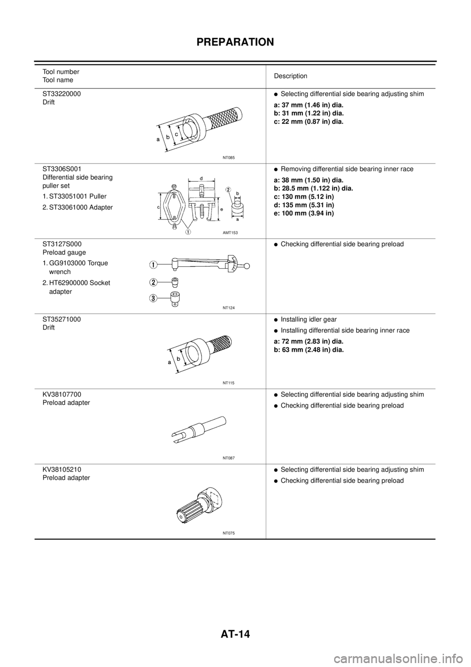
ST33220000
Drift �Selecting differential side bearing adjusting shim
a: 37 mm (1.46 in) dia.
b: 31 mm (1.22 in) dia.
c: 22 mm (0.87 in) dia.
ST3306S001
Differential side bearing
puller set
1. ST33051001 Puller
2. ST33061000 Adapter
�Removing differential side bearing inner race
a: 38 mm (1.50 in) dia.
b: 28.5 mm (1.122 in) dia.
c: 130 mm (5.12 in)
d: 135 mm (5.31 in)
e: 100 mm (3.94 in)
ST3127S000
Preload gauge
1. GG9103000 Torque
wrench
2. HT62900000 Socket
adapter
�Checking differential side bearing preload
ST35271000
Drift
�Installing idler gear
�Installing differential side bearing inner race
a: 72 mm (2.83 in) dia.
b: 63 mm (2.48 in) dia.
KV38107700
Preload adapter
�Selecting differential side bearing adjusting shim
�Checking differential side bearing preload
KV38105210
Preload adapter
�Selecting differential side bearing adjusting shim
�Checking differential side bearing preload Tool number
Tool nameDescription
NT085
AMT153
NT124
NT115
NT087
NT075
Page 2281 of 4555
A/T FLUID
AT-17
D
E
F
G
H
I
J
K
L
MA
B
AT
6. Check A/T fluid condition.
�If A/T fluid is very dark or smells burned, checking operation
of A/T. Flush cooling system after repair of A/T.
�If A/T fluid contains frictional material (clutches, bands, etc.),
replace radiator and flush cooler line using cleaning solvent
and compressed air after repair of A/T. Refer to CO-12,
"RADIATOR" , CO-15, "RADIATOR (ALUMINUM TYPE)" .
7. Install the removed A/T fluid level gauge in the A/T fluid charging
pipe.
CAUTION:
Firmly fix the A/T fluid level gauge to the A/T fluid charging
pipe using a stopper attached.
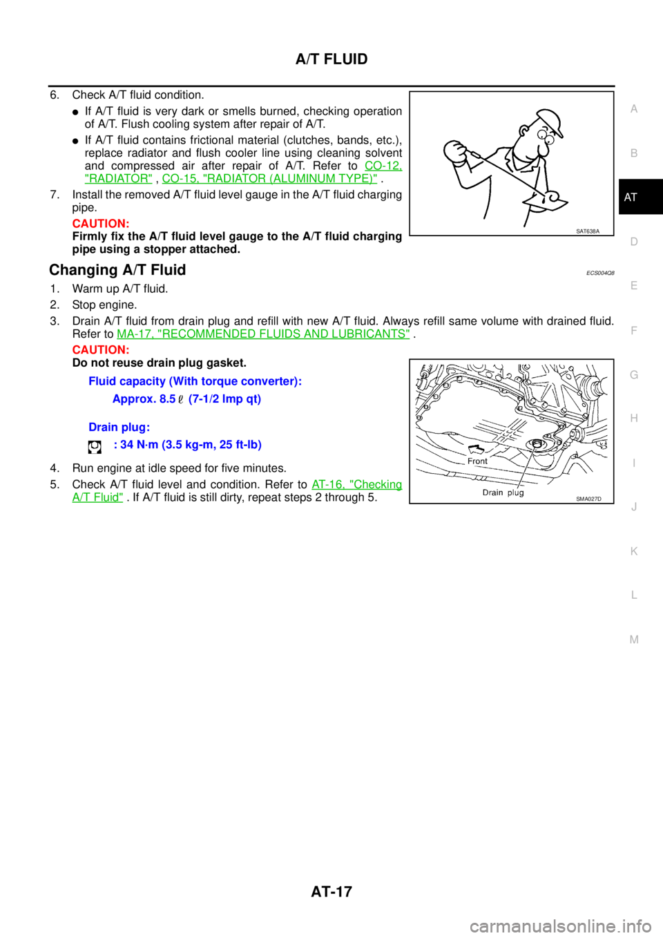
Changing A/T FluidECS004Q8
1. Warm up A/T fluid.
2. Stop engine.
3. Drain A/T fluid from drain plug and refill with new A/T fluid. Always refill same volume with drained fluid.
Refer to MA-17, "
RECOMMENDED FLUIDS AND LUBRICANTS" .
CAUTION:
Do not reuse drain plug gasket.
4. Run engine at idle speed for five minutes.
5. Check A/T fluid level and condition. Refer to AT- 1 6 , "
Checking
A/T Fluid" . If A/T fluid is still dirty, repeat steps 2 through 5.
SAT638A
Fluid capacity (With torque converter):
Approx. 8.5 (7-1/2 lmp qt)
Drain plug:
: 34 N·m (3.5 kg-m, 25 ft-lb)
SMA027D
Page 2282 of 4555
AT-18
OVERALL SYSTEM
OVERALL SYSTEMPFP:00000
Cross-Sectional View ECS00CTA
SCIA0688E
1. Band servo piston 2. Reverse clutch drum 3. Converter housing
4. Oil pump 5. Brake band 6. Reverse clutch
7. High clutch 8. Front planetary gear 9. Low one-way clutch
10. Rear planetary gear 11. Forward clutch 12. Overrun clutch
13. Low & reverse brake 14. Output gear 15. Idler gear
16. Forward one-way clutch 17. Pinion reduction gear 18. Final gear
19. Differential case 20. Input shaft 21. Torque converter
22. Side cover
Page 2286 of 4555
AT-22
OVERALL SYSTEM
Shift MechanismECS004QD
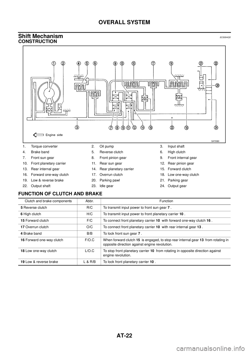
CONSTRUCTION
FUNCTION OF CLUTCH AND BRAKE
1. Torque converter 2. Oil pump 3. Input shaft
4. Brake band 5. Reverse clutch 6. High clutch
7. Front sun gear 8. Front pinion gear 9. Front internal gear
10. Front planetary carrier 11. Rear sun gear 12. Rear pinion gear
13. Rear internal gear 14. Rear planetary carrier 15. Forward clutch
16. Forward one-way clutch 17. Overrun clutch 18. Low one-way clutch
19. Low & reverse brake 20. Parking pawl 21. Parking gear
22. Output shaft 23. Idle gear 24. Output gear
SAT998I
Clutch and brake components Abbr. Function
5 Reverse clutch R/C To transmit input power to front sun gear 7 .
6 High clutch H/C To transmit input power to front planetary carrier 10 .
15 Forward clutch F/C To connect front planetary carrier 10 with forward one-way clutch 16 .
17 Overrun clutch O/C To connect front planetary carrier 10 with rear internal gear 13 .
4 Brake band B/B To lock front sun gear 7 .
16 Forward one-way clutch F/O.C When forward clutch 15 is engaged, to stop rear internal gear 13 from rotating in
opposite direction against engine revolution.
18 Low one-way clutch L/O.C To stop front planetary carrier 10 from rotating in opposite direction against
engine revolution.
19 Low & reverse brake L & R/B To lock front planetary carrier 10 .
Page 2295 of 4555
OVERALL SYSTEM
AT-31
D
E
F
G
H
I
J
K
L
MA
B
AT
TCM FunctionECS004QE
The function of the TCM is to:
�Receive input signals sent from various switches and sensors.
�Determine required line pressure, shifting point, lock-up operation, and engine brake operation.
�Send required output signals to the respective solenoids.
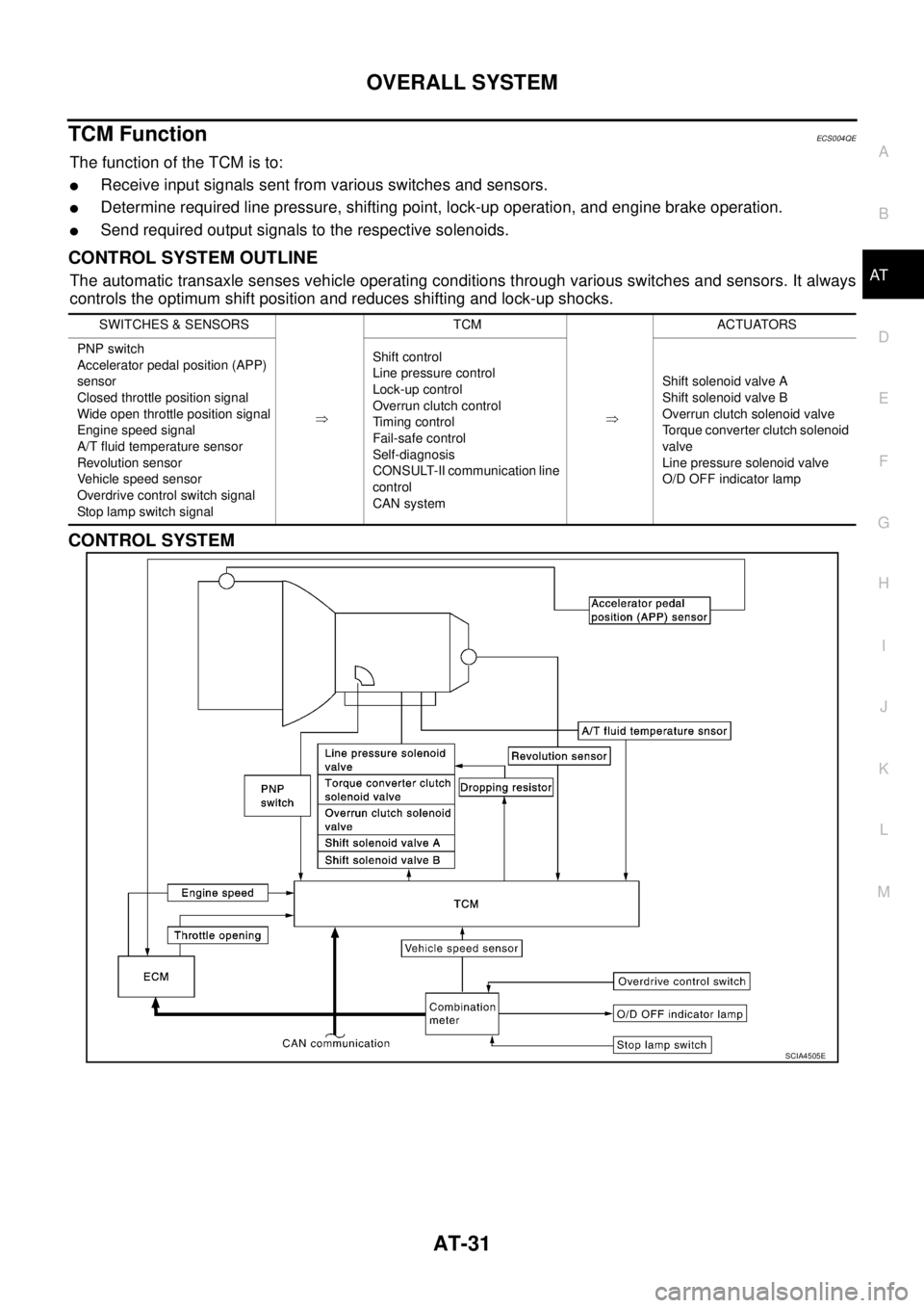
CONTROL SYSTEM OUTLINE
The automatic transaxle senses vehicle operating conditions through various switches and sensors. It always
controls the optimum shift position and reduces shifting and lock-up shocks.
CONTROL SYSTEM
SWITCHES & SENSORS
�TCM
�ACTUATORS
PNP switch
Accelerator pedal position (APP)
sensor
Closed throttle position signal
Wide open throttle position signal
Engine speed signal
A/T fluid temperature sensor
Revolution sensor
Vehicle speed sensor
Overdrive control switch signal
Stop lamp switch signalShift control
Line pressure control
Lock-up control
Overrun clutch control
Timing control
Fail-safe control
Self-diagnosis
CONSULT-II communication line
control
CAN systemShift solenoid valve A
Shift solenoid valve B
Overrun clutch solenoid valve
Torque converter clutch solenoid
valve
Line pressure solenoid valve
O/D OFF indicator lamp
SCIA4505E
Page 2298 of 4555
AT-34
OVERALL SYSTEM
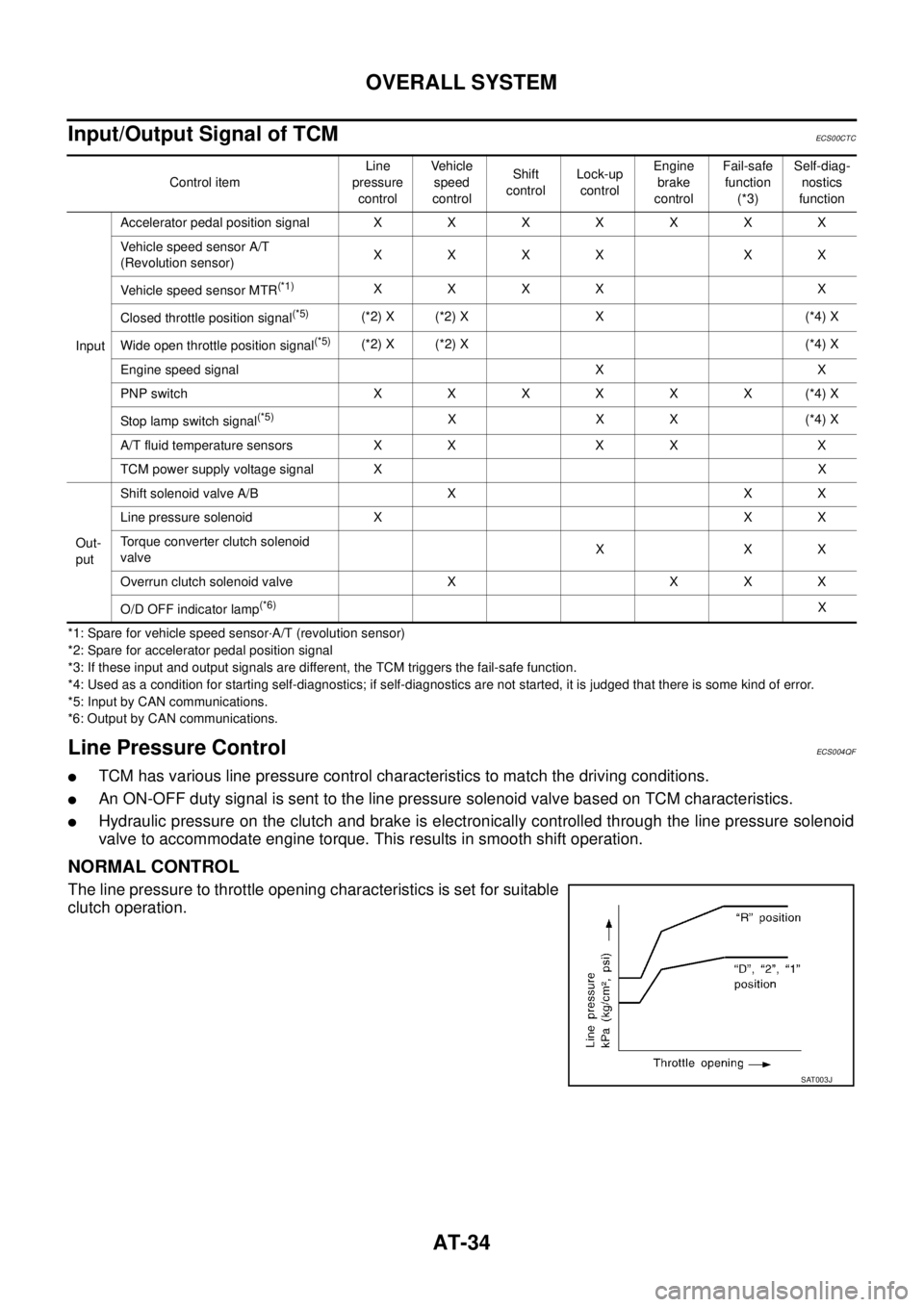
Input/Output Signal of TCMECS00CTC
*1: Spare for vehicle speed sensor·A/T (revolution sensor)
*2: Spare for accelerator pedal position signal
*3: If these input and output signals are different, the TCM triggers the fail-safe function.
*4: Used as a condition for starting self-diagnostics; if self-diagnostics are not started, it is judged that there is some kind of error.
*5: Input by CAN communications.
*6: Output by CAN communications.
Line Pressure ControlECS004QF
�TCM has various line pressure control characteristics to match the driving conditions.
�An ON-OFF duty signal is sent to the line pressure solenoid valve based on TCM characteristics.
�Hydraulic pressure on the clutch and brake is electronically controlled through the line pressure solenoid
valve to accommodate engine torque. This results in smooth shift operation.
NORMAL CONTROL
The line pressure to throttle opening characteristics is set for suitable
clutch operation.
Control itemLine
pressure
controlVehicle
speed
controlShift
controlLock-up
controlEngine
brake
controlFail-safe
function
(*3)Self-diag-
nostics
function
InputAccelerator pedal position signalXXXXXXX
Vehicle speed sensor A/T
(Revolution sensor)XXXX XX
Vehicle speed sensor MTR
(*1)XXXX X
Closed throttle position signal
(*5)(*2) X (*2) X X (*4) X
Wide open throttle position signal
(*5)(*2) X (*2) X (*4) X
Engine speed signal X X
PNP switch XXXXXX(*4) X
Stop lamp switch signal
(*5)XXX(*4) X
A/T fluid temperature sensors X X X X X
TCM power supply voltage signal XX
Out-
putShift solenoid valve A/B X X X
Line pressure solenoid X X X
Torque converter clutch solenoid
valveXXX
Overrun clutch solenoid valve X X X X
O/D OFF indicator lamp
(*6)X
SAT003J
Page 2299 of 4555
OVERALL SYSTEM
AT-35
D
E
F
G
H
I
J
K
L
MA
B
AT
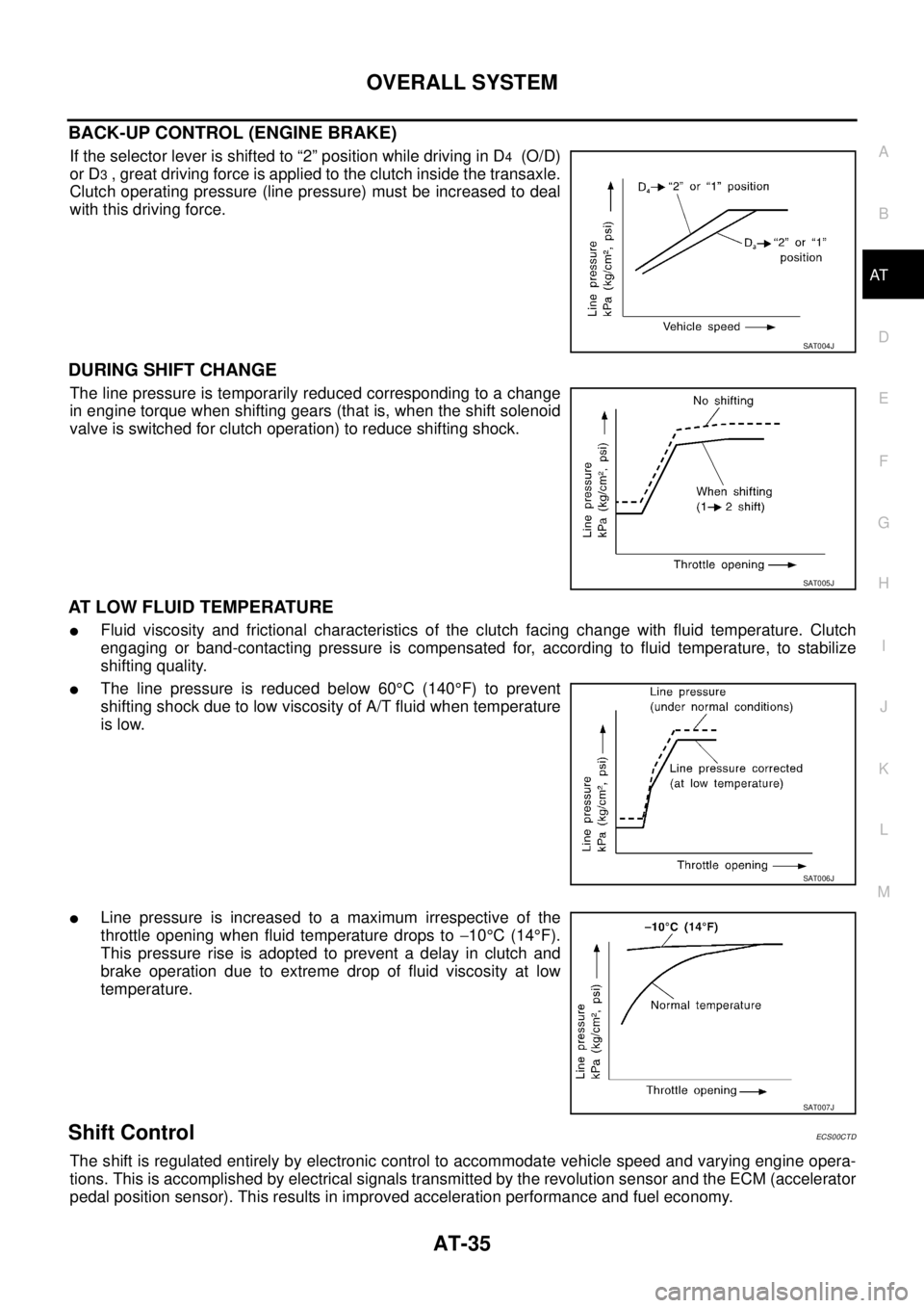
BACK-UP CONTROL (ENGINE BRAKE)
If the selector lever is shifted to “2” position while driving in D4 (O/D)
or D
3 , great driving force is applied to the clutch inside the transaxle.
Clutch operating pressure (line pressure) must be increased to deal
with this driving force.
DURING SHIFT CHANGE
The line pressure is temporarily reduced corresponding to a change
in engine torque when shifting gears (that is, when the shift solenoid
valve is switched for clutch operation) to reduce shifting shock.
AT LOW FLUID TEMPERATURE
�Fluid viscosity and frictional characteristics of the clutch facing change with fluid temperature. Clutch
engaging or band-contacting pressure is compensated for, according to fluid temperature, to stabilize
shifting quality.
�The line pressure is reduced below 60°C (140°F) to prevent
shifting shock due to low viscosity of A/T fluid when temperature
is low.
�Line pressure is increased to a maximum irrespective of the
throttle opening when fluid temperature drops to −10°C (14°F).
This pressure rise is adopted to prevent a delay in clutch and
brake operation due to extreme drop of fluid viscosity at low
temperature.
Shift ControlECS00CTD
The shift is regulated entirely by electronic control to accommodate vehicle speed and varying engine opera-
tions. This is accomplished by electrical signals transmitted by the revolution sensor and the ECM (accelerator
pedal position sensor). This results in improved acceleration performance and fuel economy.
SAT004J
SAT005J
SAT006J
SAT007J
Page 2300 of 4555
AT-36
OVERALL SYSTEM
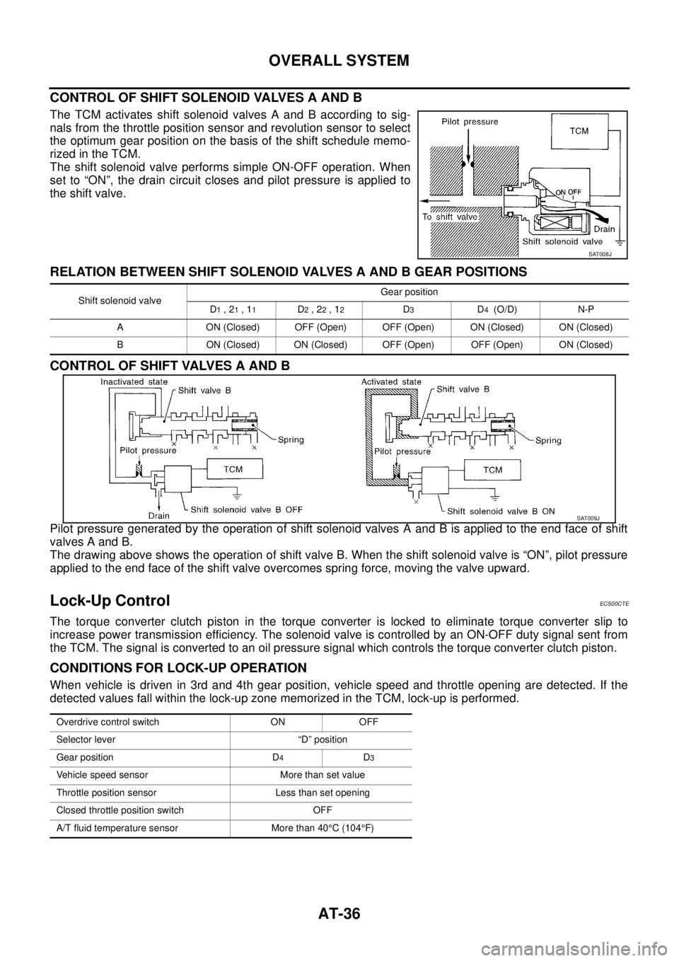
CONTROL OF SHIFT SOLENOID VALVES A AND B
The TCM activates shift solenoid valves A and B according to sig-
nals from the throttle position sensor and revolution sensor to select
the optimum gear position on the basis of the shift schedule memo-
rized in the TCM.
The shift solenoid valve performs simple ON-OFF operation. When
set to “ON”, the drain circuit closes and pilot pressure is applied to
the shift valve.
RELATION BETWEEN SHIFT SOLENOID VALVES A AND B GEAR POSITIONS
CONTROL OF SHIFT VALVES A AND B
Pilot pressure generated by the operation of shift solenoid valves A and B is applied to the end face of shift
valves A and B.
The drawing above shows the operation of shift valve B. When the shift solenoid valve is “ON”, pilot pressure
applied to the end face of the shift valve overcomes spring force, moving the valve upward.
Lock-Up ControlECS00CTE
The torque converter clutch piston in the torque converter is locked to eliminate torque converter slip to
increase power transmission efficiency. The solenoid valve is controlled by an ON-OFF duty signal sent from
the TCM. The signal is converted to an oil pressure signal which controls the torque converter clutch piston.
CONDITIONS FOR LOCK-UP OPERATION
When vehicle is driven in 3rd and 4th gear position, vehicle speed and throttle opening are detected. If the
detected values fall within the lock-up zone memorized in the TCM, lock-up is performed.
SAT008J
Shift solenoid valveGear position
D1 , 21 , 11D2 , 22 , 12D3D4 (O/D) N-P
A ON (Closed) OFF (Open) OFF (Open) ON (Closed) ON (Closed)
B ON (Closed) ON (Closed) OFF (Open) OFF (Open) ON (Closed)
SAT009J
Overdrive control switch ON OFF
Selector lever “D” position
Gear position D
4D3
Vehicle speed sensor More than set value
Throttle position sensor Less than set opening
Closed throttle position switch OFF
A/T fluid temperature sensor More than 40°C (104°F)