Page 1 of 4555

MODEL T30 SERIES
2005 NISSAN EUROPE S.A.S.
All rights reserved. No part of this Electronic Service Manual may be reproduced or stored in a retrieval system, or transmitted in any
form, or by any means, electronic, mechanical, photocopying, recording or otherwise, without the prior written permission of Nissan
Europe S.A.S., Paris, France.
A GENERAL INFORMATION
B ENGINE
C TRANSMISSION/TRANSAXLE
D DRIVELINE/AXLE
E SUSPENSION F BRAKES
G STEERING H RESTRAINTS
I BODY
J AIR CONDITIONER
K ELECTRICAL
L MAINTENANCE
M INDEXGI General Information
EM Engine Mechanical
LU Engine Lubrication System
CO Engine Cooling System
EC Engine Control System
FL Fuel System
EX Exhaust System
ACC Accelerator Control System
CL Clutch
MT Manual Transaxle
AT Automatic Transaxle
TF Transfer
PR Propeller Shaft
RFD Rear Final Drive
FAX Front Axle
RAX Rear Axle
FSU Front Suspension
RSU Rear Suspension
WT Road Wheels & Tires
BR Brake System
PB Parking Brake System
BRC Brake Control System
PS Power Steering System
SB Seat Belts
SRS Supplemental Restraint System (SRS)
BL Body, Lock & Security System
GW Glasses, Window System & Mirrors
RF Roof
EI Exterior & Interior
IP Instrument Panel
SE Seat
ATC Automatic Air Conditioner
MTC Manual AIr Conditioner
SC Starting & Charging System
LT Lighting System
DI Driver Information System
WW Wiper, Washer & Horn
BCS Body Control System
LAN LAN System
AV Audio Visual, Navigation & Telephone System
ACS Auto Cruise Control System
PG Power Supply, Ground & Circuit Elements
MA Maintenance
IDX Alphabetical Index
QUICK REFERENCE INDEX
A
B
C
D
E
F
G
H
I
J
K
L
M
Page 6 of 4555

GI-4
PRECAUTIONS
General PrecautionsEAS000FQ
�Do not operate the engine for an extended period of time without
proper exhaust ventilation.
Keep the work area well ventilated and free of any inflammable
materials. Special care should be taken when handling any
inflammable or poisonous materials, such as gasoline, refriger-
ant gas, etc. When working in a pit or other enclosed area, be
sure to properly ventilate the area before working with hazard-
ous materials.
Do not smoke while working on the vehicle.
�Before jacking up the vehicle, apply wheel chocks or other tire
blocks to the wheels to prevent the vehicle from moving. After
jacking up the vehicle, support the vehicle weight with safety
stands at the points designated for proper lifting before working
on the vehicle.
These operations should be done on a level surface.
�When removing a heavy component such as the engine or tran-
saxle/transmission, be careful not to lose your balance and drop
them. Also, do not allow them to strike adjacent parts, especially
the brake tubes and master cylinder.
�Before starting repairs which do not require battery power:
Turn off ignition switch.
Disconnect the negative battery terminal.
�If the battery terminals are disconnected, recorded memory of
radio and each control unit is erased.
�To prevent serious burns:
Avoid contact with hot metal parts.
Do not remove the radiator cap when the engine is hot.
�Dispose of drained oil or the solvent used for cleaning parts in
an appropriate manner.
�Do not attempt to top off the fuel tank after the fuel pump nozzle
shuts off automatically.
Continued refueling may cause fuel overflow, resulting in fuel
spray and possibly a fire.
�Clean all disassembled parts in the designated liquid or solvent
prior to inspection or assembly.
�Replace oil seals, gaskets, packings, O-rings, locking washers, cotter pins, self-locking nuts, etc. with new
ones.
�Replace inner and outer races of tapered roller bearings and needle bearings as a set.
�Arrange the disassembled parts in accordance with their assembled locations and sequence.
�Do not touch the terminals of electrical components which use microcomputers (such as ECM).
Static electricity may damage internal electronic components.
�After disconnecting vacuum or air hoses, attach a tag to indicate the proper connection.
�Use only the fluids and lubricants specified in this manual.
SGI285
SGI231
SEF289H
SGI233
Page 11 of 4555

HOW TO USE THIS MANUAL
GI-9
C
D
E
F
G
H
I
J
K
L
MB
GI
ComponentsEAS0015G
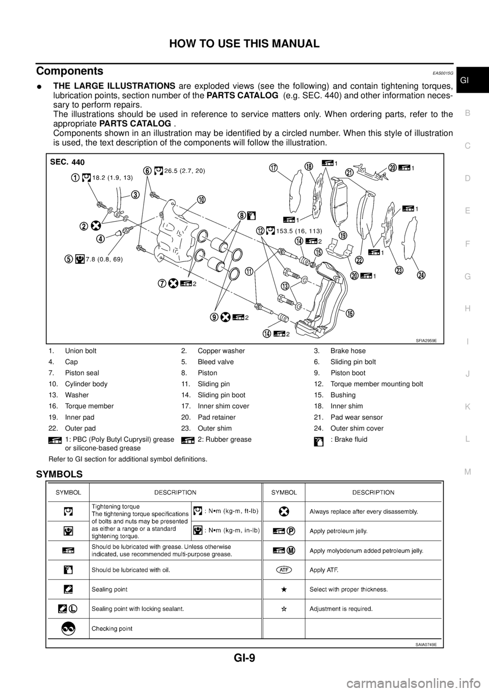
�THE LARGE ILLUSTRATIONS are exploded views (see the following) and contain tightening torques,
lubrication points, section number of the PARTS CATALOG (e.g. SEC. 440) and other information neces-
sary to perform repairs.
The illustrations should be used in reference to service matters only. When ordering parts, refer to the
appropriate PARTS CATALOG .
Components shown in an illustration may be identified by a circled number. When this style of illustration
is used, the text description of the components will follow the illustration.
SYMBOLS
1. Union bolt 2. Copper washer 3. Brake hose
4. Cap 5. Bleed valve 6. Sliding pin bolt
7. Piston seal 8. Piston 9. Piston boot
10. Cylinder body 11. Sliding pin 12. Torque member mounting bolt
13. Washer 14. Sliding pin boot 15. Bushing
16. Torque member 17. Inner shim cover 18. Inner shim
19. Inner pad 20. Pad retainer 21. Pad wear sensor
22. Outer pad 23. Outer shim 24. Outer shim cover
1: PBC (Poly Butyl Cuprysil) grease
or silicone-based grease2: Rubber grease : Brake fluid
Refer to GI section for additional symbol definitions.
SFIA2959E
SAIA0749E
Page 20 of 4555
GI-18
HOW TO USE THIS MANUAL
Harness Indication
�Letter designations next to test meter probe indicate harness
(connector) wire color.
�Connector numbers in a single circle M33 indicate harness con-
nectors.
Component Indication
Connector numbers in a double circle F211 indicate component connectors.
Switch Positions
Switches are shown in wiring diagrams as if the vehicle is in the “normal” condition.
A vehicle is in the “normal” condition when:
�ignition switch is “OFF”,
�doors, hood and trunk lid/back door are closed,
�pedals are not depressed, and
�parking brake is released.
AGI070
SGI860
Page 39 of 4555
LIFTING POINT
GI-37
C
D
E
F
G
H
I
J
K
L
MB
GI
�Place wheel chocks at both front and back of the wheels on the ground.
2-Pole Lift EAS000FJ
WARNING:
When lifting the vehicle, open the lift arms as wide as possible and ensure that the front and rear of
the vehicle are well balanced.
When setting the lift arm, do not allow the arm to contact the brake tubes, brake cable, fuel lines and
sill spoiler.
PAIA0001E
PAIA0002E
Page 42 of 4555

GI-40
TOW TRUCK TOWING
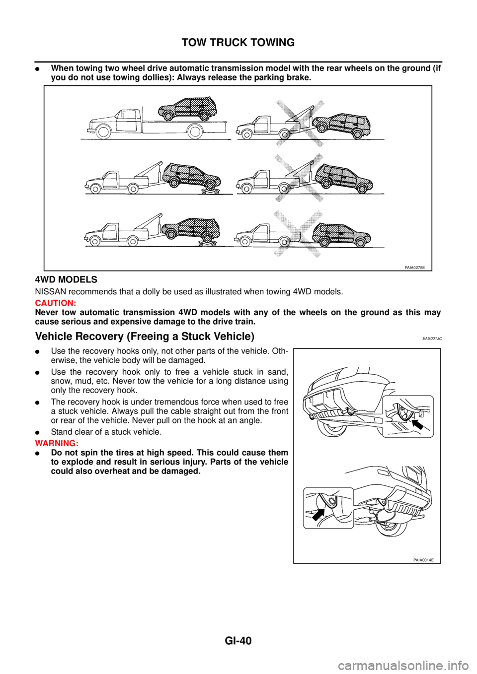
�When towing two wheel drive automatic transmission model with the rear wheels on the ground (if
you do not use towing dollies): Always release the parking brake.
4WD MODELS
NISSAN recommends that a dolly be used as illustrated when towing 4WD models.
CAUTION:
Never tow automatic transmission 4WD models with any of the wheels on the ground as this may
cause serious and expensive damage to the drive train.
Vehicle Recovery (Freeing a Stuck Vehicle) EAS001JC
�Use the recovery hooks only, not other parts of the vehicle. Oth-
erwise, the vehicle body will be damaged.
�Use the recovery hook only to free a vehicle stuck in sand,
snow, mud, etc. Never tow the vehicle for a long distance using
only the recovery hook.
�The recovery hook is under tremendous force when used to free
a stuck vehicle. Always pull the cable straight out from the front
or rear of the vehicle. Never pull on the hook at an angle.
�Stand clear of a stuck vehicle.
WARNING:
�Do not spin the tires at high speed. This could cause them
to explode and result in serious injury. Parts of the vehicle
could also overheat and be damaged.
PAIA0275E
PAIA0014E
Page 109 of 4555
![NISSAN X-TRAIL 2005 Service Repair Manual TIMING CHAIN
EM-55
[QR]
C
D
E
F
G
H
I
J
K
L
MA
EM
INSPECTION AFTER INSTALLATION
Inspection for Leaks
The following are procedures for checking fluids leak, lubricates leak and exhaust gases leak.
�B NISSAN X-TRAIL 2005 Service Repair Manual TIMING CHAIN
EM-55
[QR]
C
D
E
F
G
H
I
J
K
L
MA
EM
INSPECTION AFTER INSTALLATION
Inspection for Leaks
The following are procedures for checking fluids leak, lubricates leak and exhaust gases leak.
�B](/manual-img/5/57403/w960_57403-108.png)
TIMING CHAIN
EM-55
[QR]
C
D
E
F
G
H
I
J
K
L
MA
EM
INSPECTION AFTER INSTALLATION
Inspection for Leaks
The following are procedures for checking fluids leak, lubricates leak and exhaust gases leak.
�Before starting engine, check oil/fluid levels including engine coolant and engine oil. If less than required
quantity, fill to the specified level. Refer to MA-17, "
RECOMMENDED FLUIDS AND LUBRICANTS" .
�Use procedure below to check for fuel leakage.
–Turn ignition switch “ON” (with engine stopped). With fuel pressure applied to fuel piping, check for fuel
leakage at connection points.
–Start engine. With engine speed increased, check again for fuel leakage at connection points.
�Run engine to check for unusual noise and vibration.
NOTE:
If hydraulic pressure inside timing chain tensioner drops after removal/installation, slack in the guide may
generate a pounding noise during and just after engine start. However, this is normal. Noise will stop after
hydraulic pressure rises.
�Warm up engine thoroughly to make sure there is no leakage of fuel, exhaust gases, or any oil/fluids
including engine oil and engine coolant.
�Bleed air from lines and hoses of applicable lines, such as in cooling system.
�After cooling down engine, again check oil/fluid levels including engine oil and engine coolant. Refill to the
specified level, if necessary.
Summary of the inspection items:
* Transmission/transaxle/CVT fluid, power steering fluid, brake fluid, etc.Item Before starting engine Engine running After engine stopped
Engine coolant Level Leakage Level
Engine oil Level Leakage Level
Other oils and fluid* Level Leakage Level
Fuel Leakage Leakage Leakage
Exhaust gases — Leakage —
Page 128 of 4555
![NISSAN X-TRAIL 2005 Service Repair Manual EM-74
[QR]
CYLINDER HEAD
Summary of the inspection items:
* Transmission/transaxle/CVT fluid, power steering fluid, brake fluid, etc.
Disassembly and AssemblyEBS00KNR
DISASSEMBLY
1. Remove spark plu NISSAN X-TRAIL 2005 Service Repair Manual EM-74
[QR]
CYLINDER HEAD
Summary of the inspection items:
* Transmission/transaxle/CVT fluid, power steering fluid, brake fluid, etc.
Disassembly and AssemblyEBS00KNR
DISASSEMBLY
1. Remove spark plu](/manual-img/5/57403/w960_57403-127.png)
EM-74
[QR]
CYLINDER HEAD
Summary of the inspection items:
* Transmission/transaxle/CVT fluid, power steering fluid, brake fluid, etc.
Disassembly and AssemblyEBS00KNR
DISASSEMBLY
1. Remove spark plug with spark plug wrench (commercial service tool).
2. Remove spark plug tube, if necessary.
�Using pliers, remove it from cylinder head.
CAUTION:
�Be careful not to damage cylinder head.
�Do not remove spark plug tube if not necessary. Once removed, spark plug tube cannot be
reused because of deformation.
3. Remove valve lifter.
�Identify installation positions, and store them without mixing them up.
4. Remove valve collet.
Item Before starting engine Engine running After engine stopped
Engine coolant Level Leakage Level
Engine oil Level Leakage Level
Other oils and fluid* Level Leakage Level
Fuel Leakage Leakage Leakage
Exhaust gases — Leakage —
1. Valve collet 2. Valve spring retainer 3. Valve spring (with valve spring seat)
4. Valve oil seal 5. Valve guide 6. Cylinder head
7. Valve seat 8. Valve (INT) 9. Valve (EXH)
10. Spark plug tube 11. Spark plug
PBIC2629E