Page 1 of 4555

MODEL T30 SERIES
2005 NISSAN EUROPE S.A.S.
All rights reserved. No part of this Electronic Service Manual may be reproduced or stored in a retrieval system, or transmitted in any
form, or by any means, electronic, mechanical, photocopying, recording or otherwise, without the prior written permission of Nissan
Europe S.A.S., Paris, France.
A GENERAL INFORMATION
B ENGINE
C TRANSMISSION/TRANSAXLE
D DRIVELINE/AXLE
E SUSPENSION F BRAKES
G STEERING H RESTRAINTS
I BODY
J AIR CONDITIONER
K ELECTRICAL
L MAINTENANCE
M INDEXGI General Information
EM Engine Mechanical
LU Engine Lubrication System
CO Engine Cooling System
EC Engine Control System
FL Fuel System
EX Exhaust System
ACC Accelerator Control System
CL Clutch
MT Manual Transaxle
AT Automatic Transaxle
TF Transfer
PR Propeller Shaft
RFD Rear Final Drive
FAX Front Axle
RAX Rear Axle
FSU Front Suspension
RSU Rear Suspension
WT Road Wheels & Tires
BR Brake System
PB Parking Brake System
BRC Brake Control System
PS Power Steering System
SB Seat Belts
SRS Supplemental Restraint System (SRS)
BL Body, Lock & Security System
GW Glasses, Window System & Mirrors
RF Roof
EI Exterior & Interior
IP Instrument Panel
SE Seat
ATC Automatic Air Conditioner
MTC Manual AIr Conditioner
SC Starting & Charging System
LT Lighting System
DI Driver Information System
WW Wiper, Washer & Horn
BCS Body Control System
LAN LAN System
AV Audio Visual, Navigation & Telephone System
ACS Auto Cruise Control System
PG Power Supply, Ground & Circuit Elements
MA Maintenance
IDX Alphabetical Index
QUICK REFERENCE INDEX
A
B
C
D
E
F
G
H
I
J
K
L
M
Page 4 of 4555
GI-2 IDENTIFICATION PLATE .................................... 46
ENGINE SERIAL NUMBER ................................ 46
AUTOMATIC TRANSAXLE NUMBER ................. 47
MANUAL TRANSAXLE NUMBER ....................... 47Dimensions ............................................................. 47
Wheels & Tires ........................................................ 47
TERMINOLOGY ........................................................ 48
SAE J1930 Terminology List ................................... 48
Page 24 of 4555
GI-22
HOW TO USE THIS MANUAL
AbbreviationsEAS000G5
The following ABBREVIATIONS are used:
ABBREVIATION DESCRIPTION
A/C Air Conditioner
A/T Automatic Transaxle/Transmission
ATF Automatic Transmission Fluid
D
1Drive range 1st gear
D
2Drive range 2nd gear
D
3Drive range 3rd gear
D
4Drive range 4th gear
FR, RR Front, Rear
LH, RH Left-Hand, Right-Hand
M/T Manual Transaxle/Transmission
OD Overdrive
P/S Power Steering
SAE Society of Automotive Engineers, Inc.
SDS Service Data and Specifications
SST Special Service Tools
2WD 2-Wheel Drive
2
22nd range 2nd gear
2
12nd range 1st gear
1
21st range 2nd gear
1
11st range 1st gear
Page 25 of 4555

SERVICE INFORMATION FOR ELECTRICAL INCIDENT
GI-23
C
D
E
F
G
H
I
J
K
L
MB
GI
SERVICE INFORMATION FOR ELECTRICAL INCIDENTPFP:00000
How to Perform Efficient Diagnosis for an Electrical IncidentEAS000G6
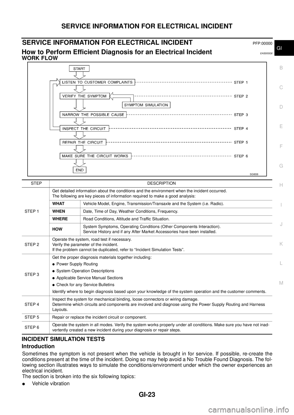
WORK FLOW
INCIDENT SIMULATION TESTS
Introduction
Sometimes the symptom is not present when the vehicle is brought in for service. If possible, re-create the
conditions present at the time of the incident. Doing so may help avoid a No Trouble Found Diagnosis. The fol-
lowing section illustrates ways to simulate the conditions/environment under which the owner experiences an
electrical incident.
The section is broken into the six following topics:
�Vehicle vibration
SGI838
STEP DESCRIPTION
STEP 1Get detailed information about the conditions and the environment when the incident occurred.
The following are key pieces of information required to make a good analysis:
WHATVehicle Model, Engine, Transmission/Transaxle and the System (i.e. Radio).
WHENDate, Time of Day, Weather Conditions, Frequency.
WHERERoad Conditions, Altitude and Traffic Situation.
HOWSystem Symptoms, Operating Conditions (Other Components Interaction).
Service History and if any After Market Accessories have been installed.
STEP 2Operate the system, road test if necessary.
Verify the parameter of the incident.
If the problem cannot be duplicated, refer to “Incident Simulation Tests”.
STEP 3Get the proper diagnosis materials together including:
�Power Supply Routing
�System Operation Descriptions
�Applicable Service Manual Sections
�Check for any Service Bulletins
Identify where to begin diagnosis based upon your knowledge of the system operation and the customer comments.
STEP 4Inspect the system for mechanical binding, loose connectors or wiring damage.
Determine which circuits and components are involved and diagnose using the Power Supply Routing and Harness
Layouts.
STEP 5 Repair or replace the incident circuit or component.
STEP 6Operate the system in all modes. Verify the system works properly under all conditions. Make sure you have not inad-
vertently created a new incident during your diagnosis or repair steps.
Page 46 of 4555

GI-44
IDENTIFICATION INFORMATION
IDENTIFICATION INFORMATIONPFP:00010
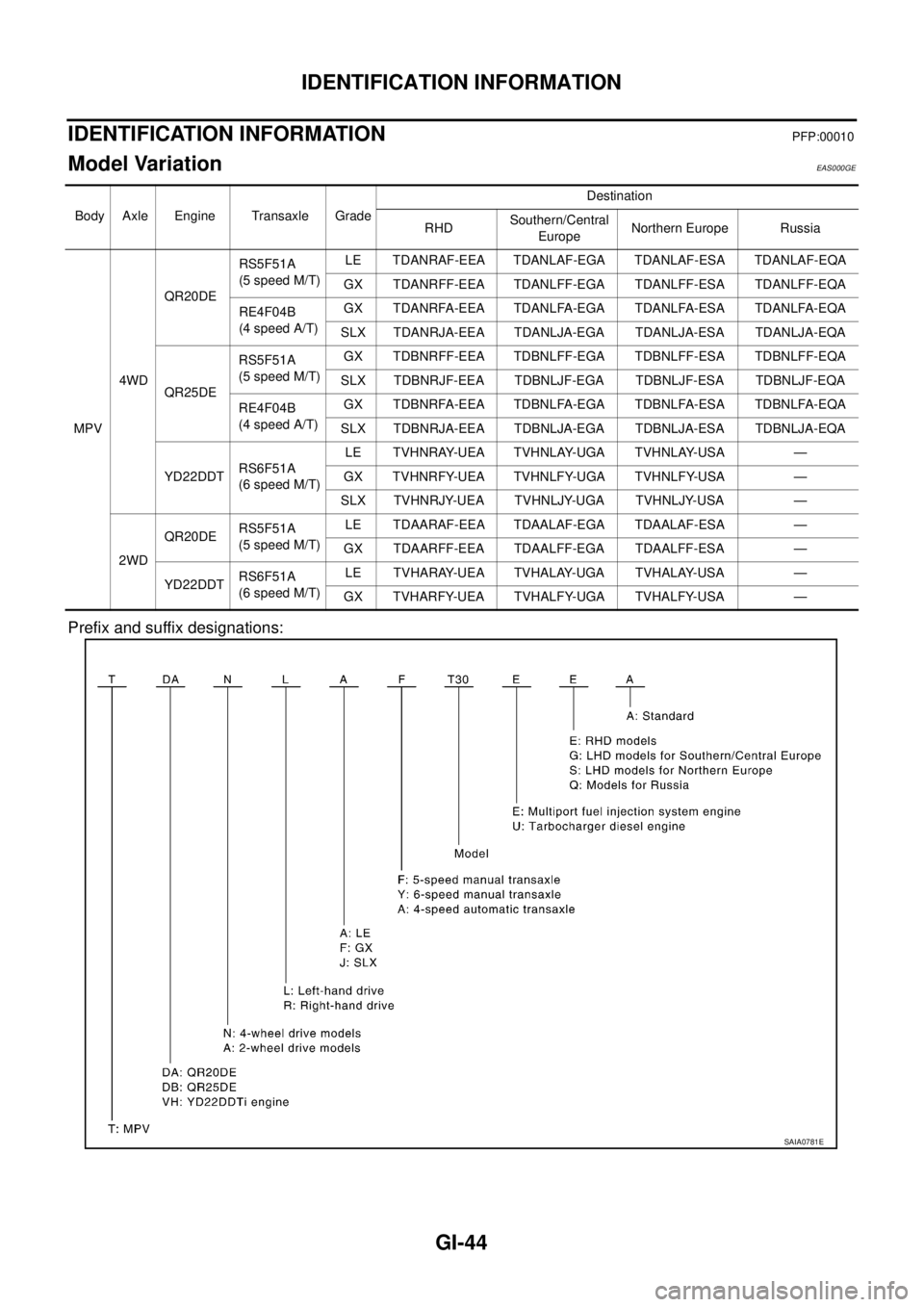
Model Variation EAS000GE
Prefix and suffix designations:
Body Axle Engine Transaxle GradeDestination
RHDSouthern/Central
EuropeNorthern Europe Russia
MPV4WDQR20DERS5F51A
(5 speed M/T)LE TDANRAF-EEA TDANLAF-EGA TDANLAF-ESA TDANLAF-EQA
GX TDANRFF-EEA TDANLFF-EGA TDANLFF-ESA TDANLFF-EQA
RE4F04B
(4 speed A/T)GX TDANRFA-EEA TDANLFA-EGA TDANLFA-ESA TDANLFA-EQA
SLX TDANRJA-EEA TDANLJA-EGA TDANLJA-ESA TDANLJA-EQA
QR25DERS5F51A
(5 speed M/T)GX TDBNRFF-EEA TDBNLFF-EGA TDBNLFF-ESA TDBNLFF-EQA
SLX TDBNRJF-EEA TDBNLJF-EGA TDBNLJF-ESA TDBNLJF-EQA
RE4F04B
(4 speed A/T)GX TDBNRFA-EEA TDBNLFA-EGA TDBNLFA-ESA TDBNLFA-EQA
SLX TDBNRJA-EEA TDBNLJA-EGA TDBNLJA-ESA TDBNLJA-EQA
YD22DDTRS6F51A
(6 speed M/T)LE TVHNRAY-UEA TVHNLAY-UGA TVHNLAY-USA —
GX TVHNRFY-UEA TVHNLFY-UGA TVHNLFY-USA —
SLX TVHNRJY-UEA TVHNLJY-UGA TVHNLJY-USA —
2WDQR20DERS5F51A
(5 speed M/T)LE TDAARAF-EEA TDAALAF-EGA TDAALAF-ESA —
GX TDAARFF-EEA TDAALFF-EGA TDAALFF-ESA —
YD22DDTRS6F51A
(6 speed M/T)LE TVHARAY-UEA TVHALAY-UGA TVHALAY-USA —
GX TVHARFY-UEA TVHALFY-UGA TVHALFY-USA —
SAIA0781E
Page 49 of 4555
IDENTIFICATION INFORMATION
GI-47
C
D
E
F
G
H
I
J
K
L
MB
GI
AUTOMATIC TRANSAXLE NUMBER
MANUAL TRANSAXLE NUMBER
Dimensions EAS000GF
Unit: mm (in)
Wheels & Tires EAS000GG
*: Option
PAIA0008E
PAIA0009E
PAIA0010E
Overall length 4,455 (175.4)
Overall width 1,765 (69.5)
Overall height1,675 (Standard, 65.9)
1,750 (With Rear spoiler or Roof rail with Driving lights, 68.9)
Front tread 1,530 (60.2)
Rear tread 1,530 (60.2)
Wheelbase 2,625 (103.3)
Conventional Spare
Road wheel/offset mm (in)15 × 6JJ Steel/40 (1.57)
16 × 6.5JJ Steel/Aluminum/40 (1.57)
17 × 6.5JJ Aluminum/40 (1.57)*Conventional
Tire size215/70R15
215/65R16
215/60R17*Conventional
Page 82 of 4555
![NISSAN X-TRAIL 2005 Service Repair Manual EM-28
[QR]
OIL PAN AND OIL STRAINER
b. Insert seal cutter (special service tool) between oil pan (upper)
and oil pan (lower).
CAUTION:
Be careful not to damage the mating surface.
4. Remove oil stra NISSAN X-TRAIL 2005 Service Repair Manual EM-28
[QR]
OIL PAN AND OIL STRAINER
b. Insert seal cutter (special service tool) between oil pan (upper)
and oil pan (lower).
CAUTION:
Be careful not to damage the mating surface.
4. Remove oil stra](/manual-img/5/57403/w960_57403-81.png)
EM-28
[QR]
OIL PAN AND OIL STRAINER
b. Insert seal cutter (special service tool) between oil pan (upper)
and oil pan (lower).
CAUTION:
Be careful not to damage the mating surface.
4. Remove oil strainer.
5. Remove oil pan (upper) with the following procedure:
a. Remove drive belt. Refer to EM-13, "
DRIVE BELTS" .
b. Remove A/C compressor with piping connected. And locate it aside temporarily with ropes or equivalent
not to disturb the following work. Refer to ATC-144, "
Removal and Installation of Compressor" .
c. Remove oil level gauge guide.
d. Remove exhaust front tube and its support. Refer to EX-2, "
EXHAUST SYSTEM" .
e. Set a suitable transmission jack under transaxle and hoist
engine with engine slinger, and then remove center member.
Refer to EM-81, "
ENGINE ASSEMBLY" .
f. Remove rear engine mounting bracket (2WD models). Refer to EM-81, "
Removal and Installation (2WD
Models)" .
g. Remove rear plate cover, and four transaxle joint bolts. Refer to MT-19, "
TRANSAXLE ASSEMBLY" (M/T
models) or AT- 4 1 3 , "
REMOVAL AND INSTALLATION" (A/T models).
h. Loosen bolts in reverse order as shown in the figure.
NOTE:
Disregard No.12 and 17 when loosening.
i. Insert seal cutter (special service tool) between oil pan (upper)
and cylinder block, and slide it by tapping on the side of the tool
with a hammer.
CAUTION:
Be careful not to damage the mating surface.
SEM365EA
PBIC0257E
SBIA0233E
SEM365EA
Page 83 of 4555
![NISSAN X-TRAIL 2005 Service Repair Manual OIL PAN AND OIL STRAINER
EM-29
[QR]
C
D
E
F
G
H
I
J
K
L
MA
EM
6. Remove O-rings at front cover side.
INSPECTION AFTER REMOVAL
Clean oil strainer if any object attached.
INSTALLATION
1. Install oil p NISSAN X-TRAIL 2005 Service Repair Manual OIL PAN AND OIL STRAINER
EM-29
[QR]
C
D
E
F
G
H
I
J
K
L
MA
EM
6. Remove O-rings at front cover side.
INSPECTION AFTER REMOVAL
Clean oil strainer if any object attached.
INSTALLATION
1. Install oil p](/manual-img/5/57403/w960_57403-82.png)
OIL PAN AND OIL STRAINER
EM-29
[QR]
C
D
E
F
G
H
I
J
K
L
MA
EM
6. Remove O-rings at front cover side.
INSPECTION AFTER REMOVAL
Clean oil strainer if any object attached.
INSTALLATION
1. Install oil pan (upper) with the following procedure:
a. Use a scraper to remove old liquid gasket from mating surfaces.
�Also remove the old liquid gasket from mating surface of cyl-
inder block.
�Remove old liquid gasket from the bolt holes and threads.
CAUTION:
Do not scratch or damage the mating surfaces when clean-
ing off old liquid gasket.
b. Apply a continuous bead of liquid gasket with a tube presser
(special service tool: WS39930000) as shown in the figure.
Use Genuine Liquid Gasket or equivalent.
CAUTION:
Apply liquid gasket to outside of bolt hole for the positions
shown by arrows.
c. Install new O-rings at front cover side.
CAUTION:
Install avoiding misalignment of O-rings.
d. Tighten bolts in numerical order as shown in the figure.
No. 12 and 17 mean double tightening of bolts No. 1 and 2.
NOTE:
Refer to the following for locating bolts.
e. Tighten transaxle joint bolts. Refer to MT-19, "
TRANSAXLE ASSEMBLY" (M/T models) or AT- 4 1 3 ,
"REMOVAL AND INSTALLATION" (A/T models).
f. Install rear plate cover.
2. Install oil strainer.
3. Install oil pan (lower) with the following procedure:
MEM108A
SBIA0253E
M6 × 20 mm (0.79 in) : No. 18, 19
M8 × 25 mm (0.98 in) : No. 1, 2, 3, 11
M8 × 45 mm (1.77 in) : No. 4, 10, 13, 14, 15, 16
M8 × 100 mm (3.97 in) : No. 5, 6, 7, 8, 9
SBIA0233E