Page 1 of 4555

MODEL T30 SERIES
2005 NISSAN EUROPE S.A.S.
All rights reserved. No part of this Electronic Service Manual may be reproduced or stored in a retrieval system, or transmitted in any
form, or by any means, electronic, mechanical, photocopying, recording or otherwise, without the prior written permission of Nissan
Europe S.A.S., Paris, France.
A GENERAL INFORMATION
B ENGINE
C TRANSMISSION/TRANSAXLE
D DRIVELINE/AXLE
E SUSPENSION F BRAKES
G STEERING H RESTRAINTS
I BODY
J AIR CONDITIONER
K ELECTRICAL
L MAINTENANCE
M INDEXGI General Information
EM Engine Mechanical
LU Engine Lubrication System
CO Engine Cooling System
EC Engine Control System
FL Fuel System
EX Exhaust System
ACC Accelerator Control System
CL Clutch
MT Manual Transaxle
AT Automatic Transaxle
TF Transfer
PR Propeller Shaft
RFD Rear Final Drive
FAX Front Axle
RAX Rear Axle
FSU Front Suspension
RSU Rear Suspension
WT Road Wheels & Tires
BR Brake System
PB Parking Brake System
BRC Brake Control System
PS Power Steering System
SB Seat Belts
SRS Supplemental Restraint System (SRS)
BL Body, Lock & Security System
GW Glasses, Window System & Mirrors
RF Roof
EI Exterior & Interior
IP Instrument Panel
SE Seat
ATC Automatic Air Conditioner
MTC Manual AIr Conditioner
SC Starting & Charging System
LT Lighting System
DI Driver Information System
WW Wiper, Washer & Horn
BCS Body Control System
LAN LAN System
AV Audio Visual, Navigation & Telephone System
ACS Auto Cruise Control System
PG Power Supply, Ground & Circuit Elements
MA Maintenance
IDX Alphabetical Index
QUICK REFERENCE INDEX
A
B
C
D
E
F
G
H
I
J
K
L
M
Page 4 of 4555
GI-2 IDENTIFICATION PLATE .................................... 46
ENGINE SERIAL NUMBER ................................ 46
AUTOMATIC TRANSAXLE NUMBER ................. 47
MANUAL TRANSAXLE NUMBER ....................... 47Dimensions ............................................................. 47
Wheels & Tires ........................................................ 47
TERMINOLOGY ........................................................ 48
SAE J1930 Terminology List ................................... 48
Page 42 of 4555

GI-40
TOW TRUCK TOWING
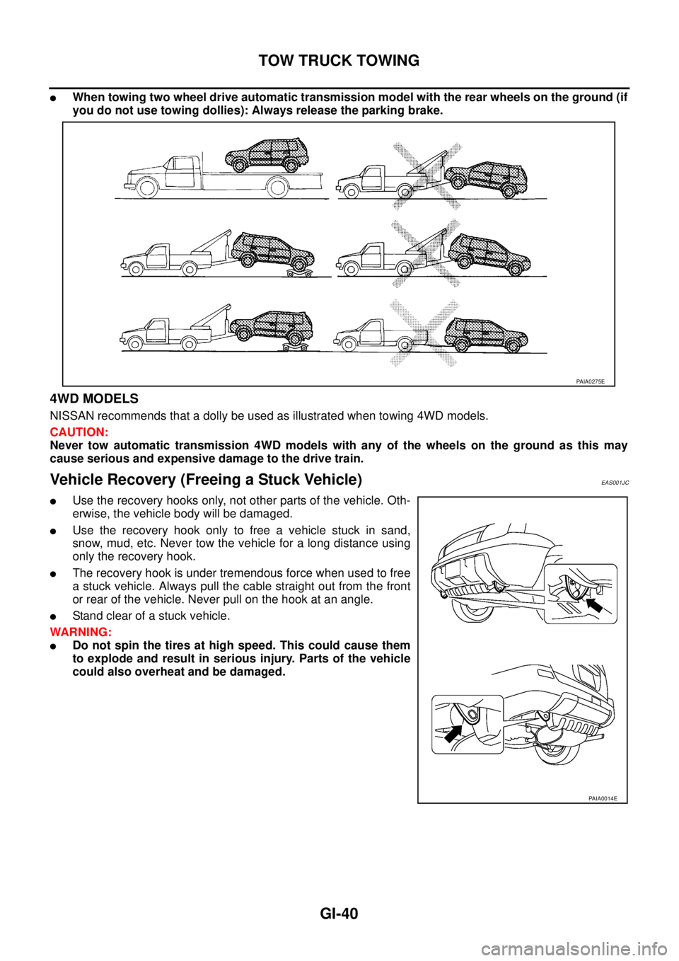
�When towing two wheel drive automatic transmission model with the rear wheels on the ground (if
you do not use towing dollies): Always release the parking brake.
4WD MODELS
NISSAN recommends that a dolly be used as illustrated when towing 4WD models.
CAUTION:
Never tow automatic transmission 4WD models with any of the wheels on the ground as this may
cause serious and expensive damage to the drive train.
Vehicle Recovery (Freeing a Stuck Vehicle) EAS001JC
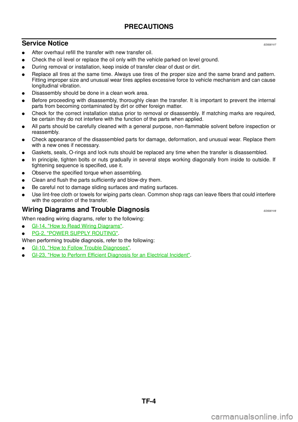
�Use the recovery hooks only, not other parts of the vehicle. Oth-
erwise, the vehicle body will be damaged.
�Use the recovery hook only to free a vehicle stuck in sand,
snow, mud, etc. Never tow the vehicle for a long distance using
only the recovery hook.
�The recovery hook is under tremendous force when used to free
a stuck vehicle. Always pull the cable straight out from the front
or rear of the vehicle. Never pull on the hook at an angle.
�Stand clear of a stuck vehicle.
WARNING:
�Do not spin the tires at high speed. This could cause them
to explode and result in serious injury. Parts of the vehicle
could also overheat and be damaged.
PAIA0275E
PAIA0014E
Page 49 of 4555
IDENTIFICATION INFORMATION
GI-47
C
D
E
F
G
H
I
J
K
L
MB
GI
AUTOMATIC TRANSAXLE NUMBER
MANUAL TRANSAXLE NUMBER
Dimensions EAS000GF
Unit: mm (in)
Wheels & Tires EAS000GG
*: Option
PAIA0008E
PAIA0009E
PAIA0010E
Overall length 4,455 (175.4)
Overall width 1,765 (69.5)
Overall height1,675 (Standard, 65.9)
1,750 (With Rear spoiler or Roof rail with Driving lights, 68.9)
Front tread 1,530 (60.2)
Rear tread 1,530 (60.2)
Wheelbase 2,625 (103.3)
Conventional Spare
Road wheel/offset mm (in)15 × 6JJ Steel/40 (1.57)
16 × 6.5JJ Steel/Aluminum/40 (1.57)
17 × 6.5JJ Aluminum/40 (1.57)*Conventional
Tire size215/70R15
215/65R16
215/60R17*Conventional
Page 362 of 4555
CO-6
[QR]
OVERHEATING CAUSE ANALYSIS
Except cool-
ing system
parts mal-
function— Overload on engineAbusive drivingHigh engine rpm under no
load
Driving in low gear for
extended time
Driving at extremely high
speed
Power train system mal-
function
— Installed improper size
wheels and tires
Dragging brakes
Improper ignition timing
Blocked or restricted air
flowBlocked bumper —
— Blocked radiator grilleInstalled car brassiere
Mud contamination or
paper clogging
Blocked radiator —
Blocked condenser
Blocked air flow
Installed large fog lamp Symptom Check items
Page 385 of 4555
OVERHEATING CAUSE ANALYSIS
CO-29
[YD22DDTi]
C
D
E
F
G
H
I
J
K
L
MA
CO
Except cool-
ing system
parts mal-
function— Overload on engineAbusive drivingHigh engine rpm under no
load
Driving in low gear for
extended time
Driving at extremely high
speed
Powertrain system mal-
function
— Installed improper size
wheels and tires
Dragging brakes
Improper ignition timing
Blocked or restricted air
flowBlocked bumper —
— Blocked radiator grilleInstalled car brassiere
Mud contamination or
paper clogging
Blocked radiator —
Blocked condenser
Blocked air flow
Installed large fog lamp Symptom Check items
Page 2808 of 4555

TF-4
PRECAUTIONS
Service NoticeEDS001V7
�After overhaul refill the transfer with new transfer oil.
�Check the oil level or replace the oil only with the vehicle parked on level ground.
�During removal or installation, keep inside of transfer clear of dust or dirt.
�Replace all tires at the same time. Always use tires of the proper size and the same brand and pattern.
Fitting improper size and unusual wear tires applies excessive force to vehicle mechanism and can cause
longitudinal vibration.
�Disassembly should be done in a clean work area.
�Before proceeding with disassembly, thoroughly clean the transfer. It is important to prevent the internal
parts from becoming contaminated by dirt or other foreign matter.
�Check for the correct installation status prior to removal or disassembly. If matching marks are required,
be certain they do not interfere with the function of the parts when applied.
�All parts should be carefully cleaned with a general purpose, non-flammable solvent before inspection or
reassembly.
�Check appearance of the disassembled parts for damage, deformation, and unusual wear. Replace them
with a new ones if necessary.
�Gaskets, seals, O-rings and lock nuts should be replaced any time when the transfer is disassembled.
�In principle, tighten bolts or nuts gradually in several steps working diagonally from inside to outside. If
tightening sequence is specified, use it.
�Observe the specified torque when assembling.
�Clean and flush the parts sufficiently and blow-dry them.
�Be careful not to damage sliding surfaces and mating surfaces.
�Use lint-free cloth or towels for wiping parts clean. Common shop rags can leave fibers that could interfere
with the operation of the transfer.
Wiring Diagrams and Trouble DiagnosisEDS001V8
When reading wiring diagrams, refer to the following:
�GI-14, "How to Read Wiring Diagrams".
�PG-2, "POWER SUPPLY ROUTING".
When performing trouble diagnosis, refer to the following:
�GI-10, "How to Follow Trouble Diagnoses".
�GI-23, "How to Perform Efficient Diagnosis for an Electrical Incident".
Page 2816 of 4555

TF-12
ALL MODE 4X4 SYSTEM
4WD MODE SWITCH
AUTO Mode
�Electronic control allows optimal distribution of torque to front/rear wheels to match road conditions.
�4WD mode makes possible stable driving, with no wheel spin, on snowy roads or other slippery surfaces.
�On roads which do not require 4WD, AUTO mode contributes to improved fuel economy by driving in con-
ditions close to front-wheel drive.
�Sensor inputs determine the vehicle's turning condition, and tight cornering/braking are controlled by dis-
tributing optimum torque to rear wheels.
LOCK Mode
�Front/rear wheel torque distribution is fixed, ensuring stable driving when climbing slopes.
�Vehicle will switch automatically to AUTO mode if vehicle speed increases. If vehicle speed then
decreases, the vehicle automatically returns to direct 4-wheel driving conditions.
�LOCK mode will change to AUTO mode automatically, when the vehicle speed exceeds approx. 30 km/h
(19 MPH). The LOCK indicator light keeps illuminating.
NOTE:
If there is a significant difference in pressure or wear between tires, full vehicle performance is not available.
LOCK mode may be prohibited, or speeds at which LOCK mode is enabled may be restricted detecting tire
conditions.
2WD Mode
Vehicle is in front-wheel drive.
NOTE:
�If front wheels are slipping in 2WD mode, do not switch to AUTO or LOCK. This can cause difficulties for
the system.
�Even if the 4WD mode switch is in 2WD mode, the 4WD control unit occasionally automatically change to
AUTO mode depending on the driving condition (For example; Depressing the acceleration firmly). This is
not malfunction. However, 4WD indicator lamp dose not illuminate.
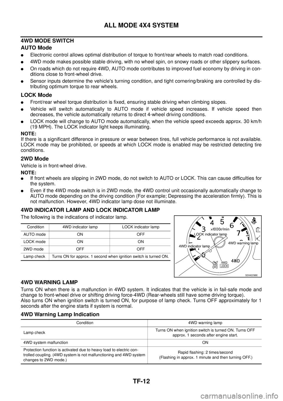
4WD INDICATOR LAMP AND LOCK INDICATOR LAMP
The following is the indications of indicator lamp.
4WD WARNING LAMP
Turns ON when there is a malfunction in 4WD system. It indicates that the vehicle is in fail-safe mode and
change to front-wheel drive or shifting driving force-4WD (Rear-wheels still have some driving torque).
Also turns ON when ignition switch is turned ON, for purpose of lamp check. Turns OFF approximately for 1
seconds after the engine starts if system is normal.
4WD Warning Lamp Indication
Condition 4WD indicator lamp LOCK indicator lamp
AUTO mode ON OFF
LOCK mode ON ON
2WD mode OFF OFF
Lamp check Turns ON for approx. 1 second when ignition switch is turned ON.
SDIA2298E
Condition 4WD warning lamp
Lamp checkTurns ON when ignition switch is turned ON. Turns OFF
approx. 1 seconds after engine start.
4WD system malfunctionON
Protection function is activated due to heavy load to electric con-
trolled coupling. (4WD system is not malfunctioning and 4WD system
changes to 2WD mode.)Rapid flashing: 2 times/second
(Flashing in approx. 1 minute and then turning OFF.)