Page 2951 of 4555

RAX-7
C
E
F
G
H
I
J
K
L
MA
B
RAX
INSTALLATION
�Install in the reverse order of removal. For tightening torque refer to RAX-6, \"COMPONENT\" .
�Perform final tightening of nuts and bolt")
WHEEL HUB (2WD)
RAX-7
C
E
F
G
H
I
J
K
L
MA
B
RAX
INSTALLATION
�Install in the reverse order of removal. For tightening torque refer to RAX-6, "COMPONENT" .
�Perform final tightening of nuts and bolts on each link mounting part (rubber bushing) under unladen con-
ditions with tires on level ground. Check wheel alignment. Refer to RSU-6, "
Wheel Alignment" .
�Check wheel sensor harness for proper connection. Refer to BRC-46, "WHEEL SENSORS" .
Disassembly and AssemblyEDS0034I
DISASSEMBLY
CAUTION:
Do not disassemble if wheel bearing has no trouble.
1. Remove caulked of lock nut, and then remove lock nut from axle housing.
2. Remove sensor rotor from axle housing.
3. Set axle housing on vise at point where strut is attached. Using
a sliding hammer [SST] and attachment [SST] to remove wheel
hub from axle housing.
CAUTION:
When placing on vise, be careful not to damage strut
mounting surface of axle housing. Use an aluminum plate
or suitable tool.
4. Using a drift [SST] and a puller (suitable tool), press wheel bear-
ing outer side inner race from wheel hub.
5. Using a flat-bladed screwdriver or similar tool to remove snap
ring from axle housing.
6. Using a drift [SST] and a press wheel bearing from axle housing.
FAC0104D
SDIA2440E
SDIA0155E
Page 2966 of 4555
FSU-2
PRECAUTIONS
PRECAUTIONSPFP:00001
CautionEES0006Z
�When installing rubber bushings, final tightening must be carried out under unladen conditions with tires
on flat, level ground. Oil will shorten the life of rubber bushings. Be sure to wipe off any spilled oil.
�“Unladen condition” means that fuel, coolant and lubricant are full and ready for drive. However, spare tire,
jack, and hand tools should be unloaded.
�After installing the removed suspension parts, always check wheel alignment and adjust if necessary.
�Replace the caulking nut with a new one. Install a new nut without wiping the oil off before tightening.
Page 2968 of 4555
 TROUBLESHOOTING
NOISE, VIBRATION AND HARSHNESS (NVH) TROUBLESHOOTINGPFP:00003
NVH Troubleshooting ChartEES000ID
Use the chart below to help you find the ca")
FSU-4
NOISE, VIBRATION AND HARSHNESS (NVH) TROUBLESHOOTING
NOISE, VIBRATION AND HARSHNESS (NVH) TROUBLESHOOTINGPFP:00003
NVH Troubleshooting ChartEES000ID
Use the chart below to help you find the cause of the symptom. If necessary, repair or replace these parts.
×: ApplicableReference page
FSU-5 FSU-8—
—
—
FSU-5 FSU-6 FSU-11
NVH in PR section
NVH in RFD section.
NVH in RAX and RSU section.
NVH in WT section.
NVH in WT section.
NVH in RAX section.
NVH in BR section.
NVH in PS section.
Possible cause and SUSPECTED PARTS
Improper installation, looseness
Shock absorber deformation, damage or deflection
Bushing or mounting deterioration
Parts interference
Spring fatigue
Suspension looseness
Incorrect wheel alignment
Stabilizer bar fatigue
PROPELLER SHAFT
DIFFERENTIAL
REAR AXLE AND REAR SUSPENSION
TIRES
ROAD WHEEL
DRIVE SHAFT
BRAKES
STEERING
Symptom FRONT SUSPENSIONNoise××××× × ××× ×××××
Shake×××× × × × ×××××
Vibration××××× × ×× × ×
Shimmy×××× × ××× ××
Judder××× ××× ××
Poor quality ride or han-
dling×× × × × ×× × × ×
Page 2982 of 4555
 TROUBLESHOOTING
NOISE, VIBRATION AND HARSHNESS (NVH) TROUBLESHOOTINGPFP:00003
NVH Troubleshooting ChartEES000IE
Use the chart below to help you find the ca")
RSU-4
NOISE, VIBRATION AND HARSHNESS (NVH) TROUBLESHOOTING
NOISE, VIBRATION AND HARSHNESS (NVH) TROUBLESHOOTINGPFP:00003
NVH Troubleshooting ChartEES000IE
Use the chart below to help you find the cause of the symptom. If necessary, repair or replace these parts.
×: ApplicableReference page
RSU-5RSU-8—
—
—
RSU-5 RSU-6RSU-5
NVH in PR section.
NVH in RFD section.
NVH in FAX and FSU sections.
NVH in WT section.
NVH in WT section.
NVH in RAX section.
NVH in BR section.
NVH in PS section.
Possible cause and SUSPECTED PARTS
Improper installation, looseness
Shock absorber deformation, damage or deflection
Bushing or mounting deterioration
Parts interference
Spring fatigue
Suspension looseness
Incorrect wheel alignment
Stabilizer bar fatigue
PROPELLER SHAFT
DIFFERENTIAL
FRONT AXLE AND FRONT SUSPENSION
TIRES
ROAD WHEEL
DRIVE SHAFT
BRAKES
STEERING
Symptom REAR SUSPENSIONNoise×××××× ××××××××
Shake×××× × × ××××××
Vibration××××× × ×× × ×
Shimmy×××× × ××× ××
Judder ××× ××× ××
Poor quality ride or
handling××××× ×× ×××
Page 2989 of 4555
REAR PARALLEL LINK
RSU-11
C
D
F
G
H
I
J
K
L
MA
B
RSU
REAR PARALLEL LINKPFP:55121
Removal and InstallationEES0007K
REMOVAL
1. Remove tyre, Raise vehicle.
2. Remove rear parallel link mounting bolts and nuts. Remove it from vehicle.
INSPECTION AFTER REMOVAL
�If rear parallel link has deformation, cracks, or damage, replace rear parallel link assembly. If its busing
has damage, also replace rear parallel link assembly.
INSTALLATION
�Refer to RSU-5, "Components" for tightening torque and reverse the removal procedure for installation.
�Suspension member-side mounting bolt is also used as toe-in adjusting bolt. Tighten bolt with vehicle
unladen and tires on the ground. After tightened, be sure to carry out toe-in adjustment. Refer to RSU-6,
"TOE-IN" .
CAUTION:
Be sure to adjust equally on RH and LH side with adjusting bolt.
Page 3380 of 4555

AV-38
NAVIGATION SYSTEM
NAVIGATION SYSTEMPFP:25915
System DescriptionEKS00M7F
NAVIGATION SYSTEM
Location Detection Principle
The navigation system periodically calculates the vehicle's current
position according to the following three signals:
�Travel distance of the vehicle as determined by the vehicle
speed sensor
�Turning angle of the vehicle as determined by the gyroscope
(angular velocity sensor)
�Direction of vehicle travel as determined by the GPS antenna
(GPS information)
The current position of the vehicle is then identified by comparing the
calculated vehicle position with map data read from the map DVD-
ROM, which is stored in the DVD-ROM drive (map-matching), and
indicated on the screen as a vehicle mark. More accurate data is judged and used by comparing vehicle posi-
tion detection results found by the GPS with the result by map-matching.
The current vehicle position will be calculated by detecting the dis-
tance the vehicle moved from the previous calculation point and its
direction.
�Travel distance
Travel distance calculations are based on the vehicle speed
sensor input signal. Therefore, the calculation may become
incorrect as the tires wear down. To prevent this, an automatic
distance correction function has been adopted.
�Travel direction
Change in the travel direction of the vehicle is calculated by a
gyroscope (angular velocity sensor) and a GPS antenna (GPS
information). They have both advantages and disadvantages.
More accurate traveling direction is detected because priorities are set for the signals from these two
devices according to the situation.
SKIB1058E
SEL684V
Type Advantage Disadvantage
Gyroscope
(angular velocity sensor)Can detect the vehicle's turning angle quite
accurately.Direction errors may accumulate when vehicle is
driven for long distances without stopping.
GPS antenna
(GPS information)Can detect the vehicle's travel direction
(North/South/East/West).Correct direction cannot be detected when vehi-
cle speed is low.
Page 3420 of 4555
AV-78
NAVIGATION SYSTEM
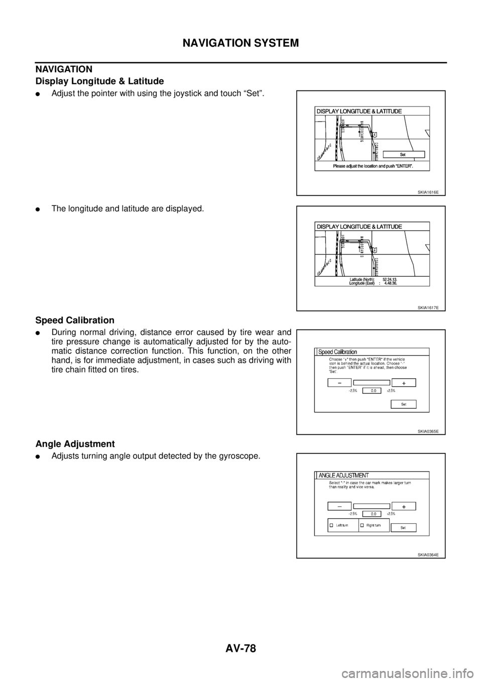
NAVIGATION
Display Longitude & Latitude
�Adjust the pointer with using the joystick and touch “Set”.
�The longitude and latitude are displayed.
Speed Calibration
�During normal driving, distance error caused by tire wear and
tire pressure change is automatically adjusted for by the auto-
matic distance correction function. This function, on the other
hand, is for immediate adjustment, in cases such as driving with
tire chain fitted on tires.
Angle Adjustment
�Adjusts turning angle output detected by the gyroscope.
SKIA1616E
SKIA1617E
SKIA0365E
SKIA0364E
Page 3445 of 4555

NAVIGATION SYSTEM
AV-103
C
D
E
F
G
H
I
J
L
MA
B
AV
PlaceIn a parking lot When driving in a parking lot, or other loca-
tion where there are no roads on the map,
matching may place the vehicle mark on a
nearby road. When the vehicle returns to
the road, the vehicle mark may have devi-
ated from the correct location.
When driving in circle or turning the steer-
ing wheel repeatedly, direction errors accu-
mulate, and the vehicle mark may deviate
from the correct location.
If after traveling about 10km
(6miles) the correct location
has not been restored, perform
location correction and, if nec-
essary, direction correction. Turntable
When the ignition switch is off, the naviga-
tion system cannot get the signal from the
gyroscope (angular speed sensor). There-
fore, the displayed direction may be wrong
and the correct road may not be easily
returned to after rotating the vehicle on a
turntable with the ignition off.
Slippery roads On snow, wet roads, gravel, or other roads
where tires may slip easily, accumulated
mileage errors may cause the vehicle mark
to deviate from the correct road.
Slopes When parking in sloped garages, when
traveling on banked roads, or in other
cases where the vehicle turns when tilted,
an error in the turning angle will occur, and
the vehicle mark may deviate from the
road.
Map dataRoad not displayed on the map screen
When driving on new roads or other roads
not displayed on the map screen, map
matching does not function correctly and
matches the location to a nearby road.
When the vehicle returns to a road which is
on the map, the vehicle mark may deviate
from the correct road.
Different road pattern
(Changed due to repair)
If the road pattern stored in the map data
and the actual road pattern are different,
map matching does not function correctly
and matches the location to a nearby road.
The vehicle mark may deviate from the
correct road.
VehicleUse of tire chains
When tire chains are used, the mileage is
not correctly detected, and the vehicle
mark may deviate from the correct road.Drive the vehicle for a while. If
the distance is still deviated,
adjust it by using the distance
adjustment function. (If the tire
chain is removed, recover the
original value.) Cause (condition) Driving condition Remarks (correction, etc.)
SEL709V
SEL710V
SEL699V
ELK0201D