2005 NISSAN NAVARA transmission
[x] Cancel search: transmissionPage 327 of 3171
ASSEMBLY
AT-319
D
E
F
G
H
I
J
K
L
MA
B
AT
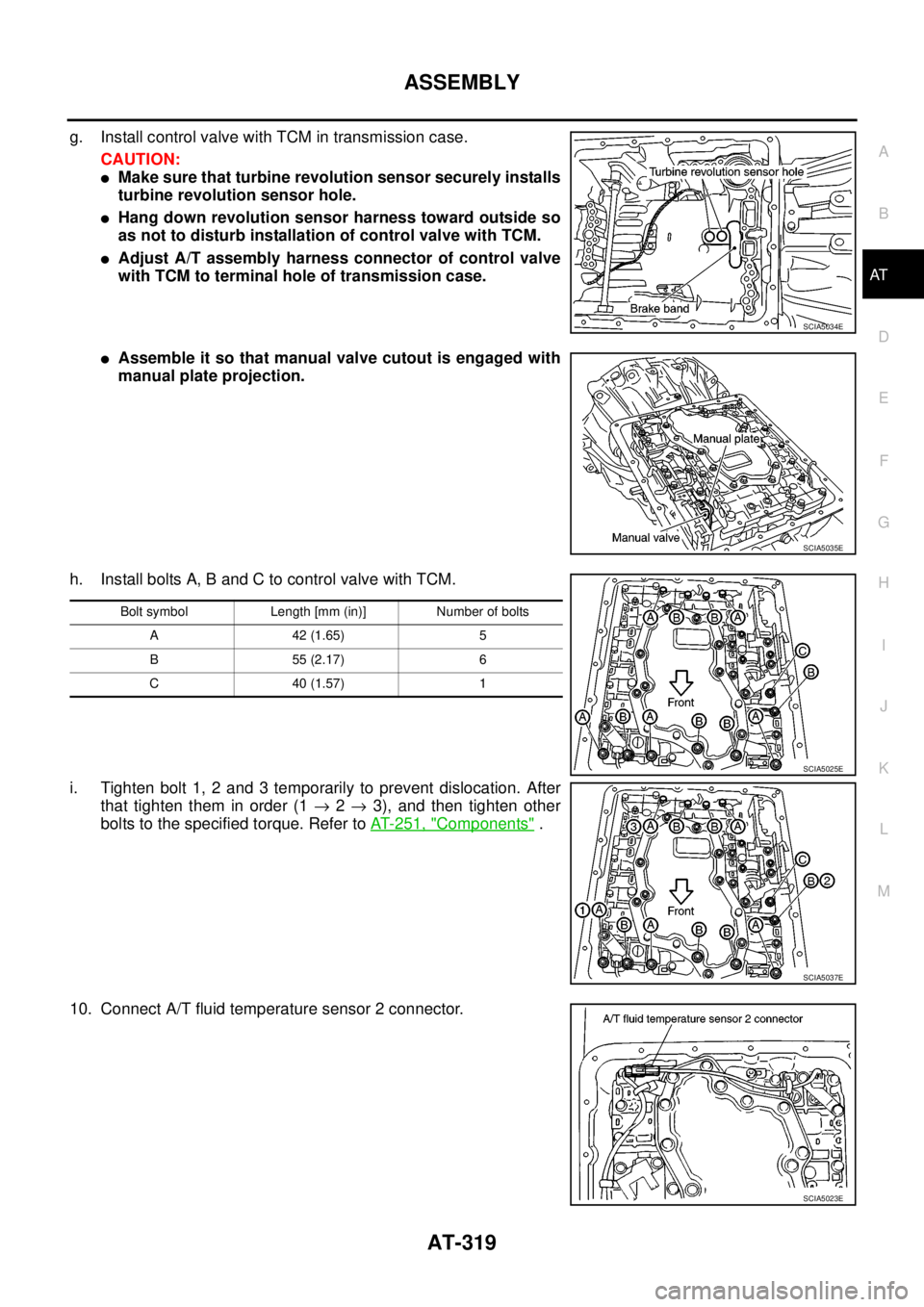
g. Install control valve with TCM in transmission case.
CAUTION:
lMake sure that turbine revolution sensor securely installs
turbine revolution sensor hole.
lHang down revolution sensor harness toward outside so
as not to disturb installation of control valve with TCM.
lAdjust A/T assembly harness connector of control valve
with TCM to terminal hole of transmission case.
lAssemble it so that manual valve cutout is engaged with
manual plate projection.
h. Install bolts A, B and C to control valve with TCM.
i. Tighten bolt 1, 2 and 3 temporarily to prevent dislocation. After
that tighten them in order (1®2®3), and then tighten other
bolts to the specified torque. Refer toAT- 2 5 1 , "
Components".
10. Connect A/T fluid temperature sensor 2 connector.
SCIA5034E
SCIA5035E
Bolt symbol Length [mm (in)] Number of bolts
A42(1.65) 5
B55(2.17) 6
C40(1.57) 1
SCIA5025E
SCIA5037E
SCIA5023E
Page 329 of 3171
ASSEMBLY
AT-321
D
E
F
G
H
I
J
K
L
MA
B
AT
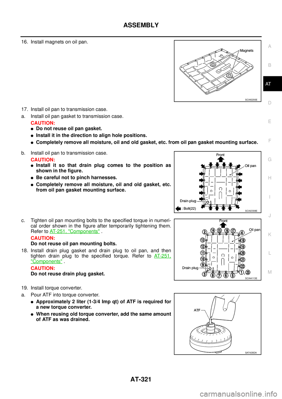
16. Install magnets on oil pan.
17. Install oil pan to transmission case.
a. Install oil pan gasket to transmission case.
CAUTION:
lDo not reuse oil pan gasket.
lInstall it in the direction to align hole positions.
lCompletely remove all moisture, oil and old gasket, etc. from oil pan gasket mounting surface.
b. Install oil pan to transmission case.
CAUTION:
lInstall it so that drain plug comes to the position as
shown in the figure.
lBe careful not to pinch harnesses.
lCompletely remove all moisture, oil and old gasket, etc.
from oil pan gasket mounting surface.
c. Tighten oil pan mounting bolts to the specified torque in numeri-
cal order shown in the figure after temporarily tightening them.
Refer toAT- 2 5 1 , "
Components".
CAUTION:
Do not reuse oil pan mounting bolts.
18. Install drain plug gasket and drain plug to oil pan, and then
tighten drain plug to the specified torque. Refer toAT-251,
"Components".
CAUTION:
Do not reuse drain plug gasket.
19. Install torque converter.
a. Pour ATF into torque converter.
lApproximately 2 liter (1-3/4 Imp qt) of ATF is required for
a new torque converter.
lWhen reusing old torque converter, add the same amount
of ATF as was drained.
SCIA5200E
SCIA2308E
SCIA4113E
SAT428DA
Page 331 of 3171
SERVICE DATA AND SPECIFICATIONS (SDS)
AT-323
D
E
F
G
H
I
J
K
L
MA
B
AT
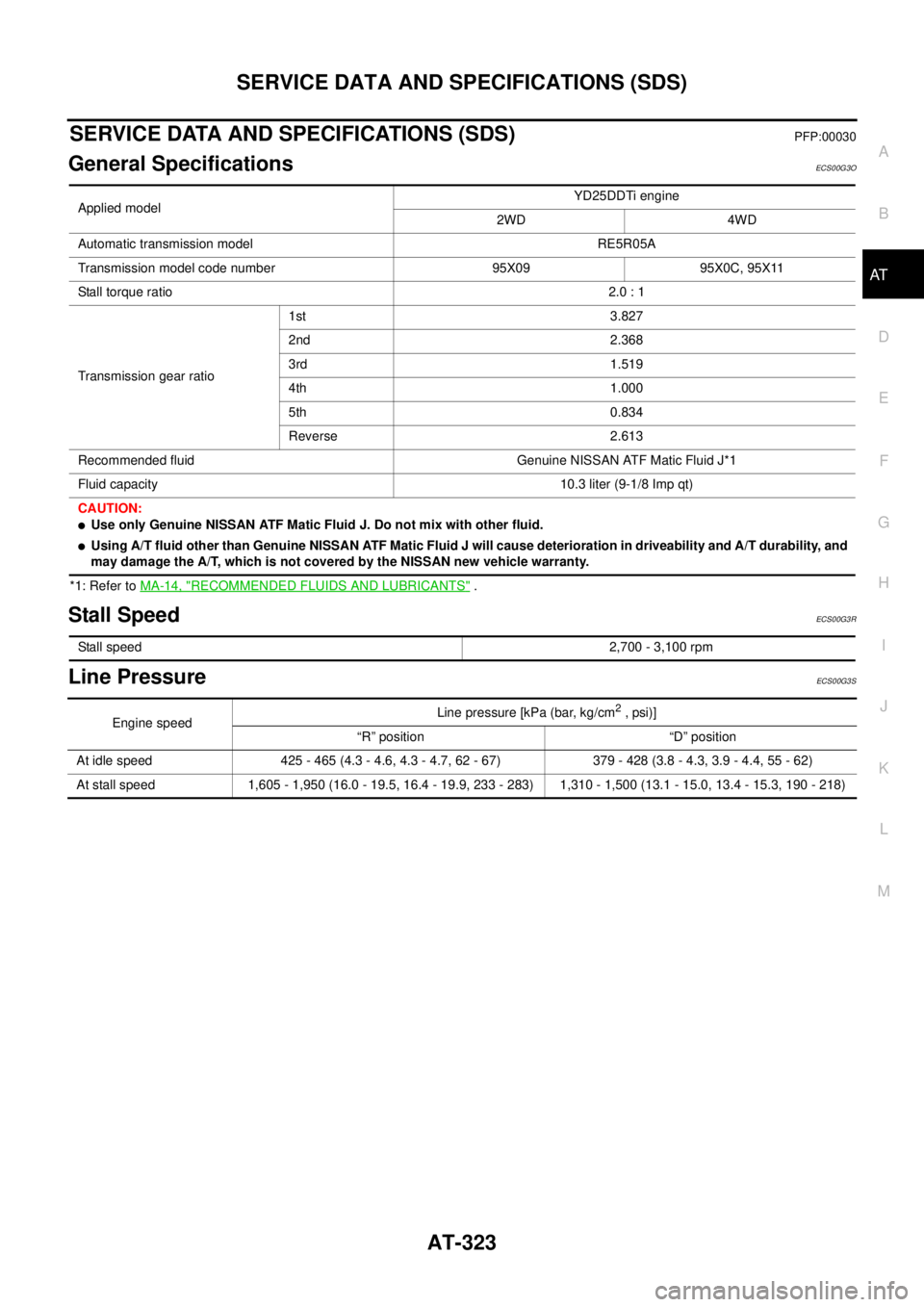
SERVICE DATA AND SPECIFICATIONS (SDS)PFP:00030
General SpecificationsECS00G3O
*1: Refer toMA-14, "RECOMMENDED FLUIDS AND LUBRICANTS".
Stall SpeedECS00G3R
Line PressureECS00G3S
Applied modelYD25DDTi engine
2WD 4WD
Automatic transmission model RE5R05A
Transmission model code number 95X09 95X0C, 95X11
Stall torque ratio2.0 : 1
Transmission gear ratio1st 3.827
2nd 2.368
3rd 1.519
4th 1.000
5th 0.834
Reverse 2.613
Recommended fluid Genuine NISSAN ATF Matic Fluid J*1
Fluid capacity 10.3 liter (9-1/8 Imp qt)
CAUTION:
lUse only Genuine NISSAN ATF Matic Fluid J. Do not mix with other fluid.
lUsing A/T fluid other than Genuine NISSAN ATF Matic Fluid J will cause deterioration in driveability and A/T durability, and
may damage the A/T, which is not covered by the NISSAN new vehicle warranty.
Stall speed2,700 - 3,100 rpm
Engine speedLine pressure [kPa (bar, kg/cm2,psi)]
“R” position “D” position
At idle speed 425 - 465 (4.3 - 4.6, 4.3 - 4.7, 62 - 67) 379 - 428 (3.8 - 4.3, 3.9 - 4.4, 55 - 62)
At stall speed 1,605 - 1,950 (16.0 - 19.5, 16.4 - 19.9, 233 - 283) 1,310 - 1,500 (13.1 - 15.0, 13.4 - 15.3, 190 - 218)
Page 521 of 3171
SYSTEM DESCRIPTION
AV-33
C
D
E
F
G
H
I
J
L
MA
B
AV
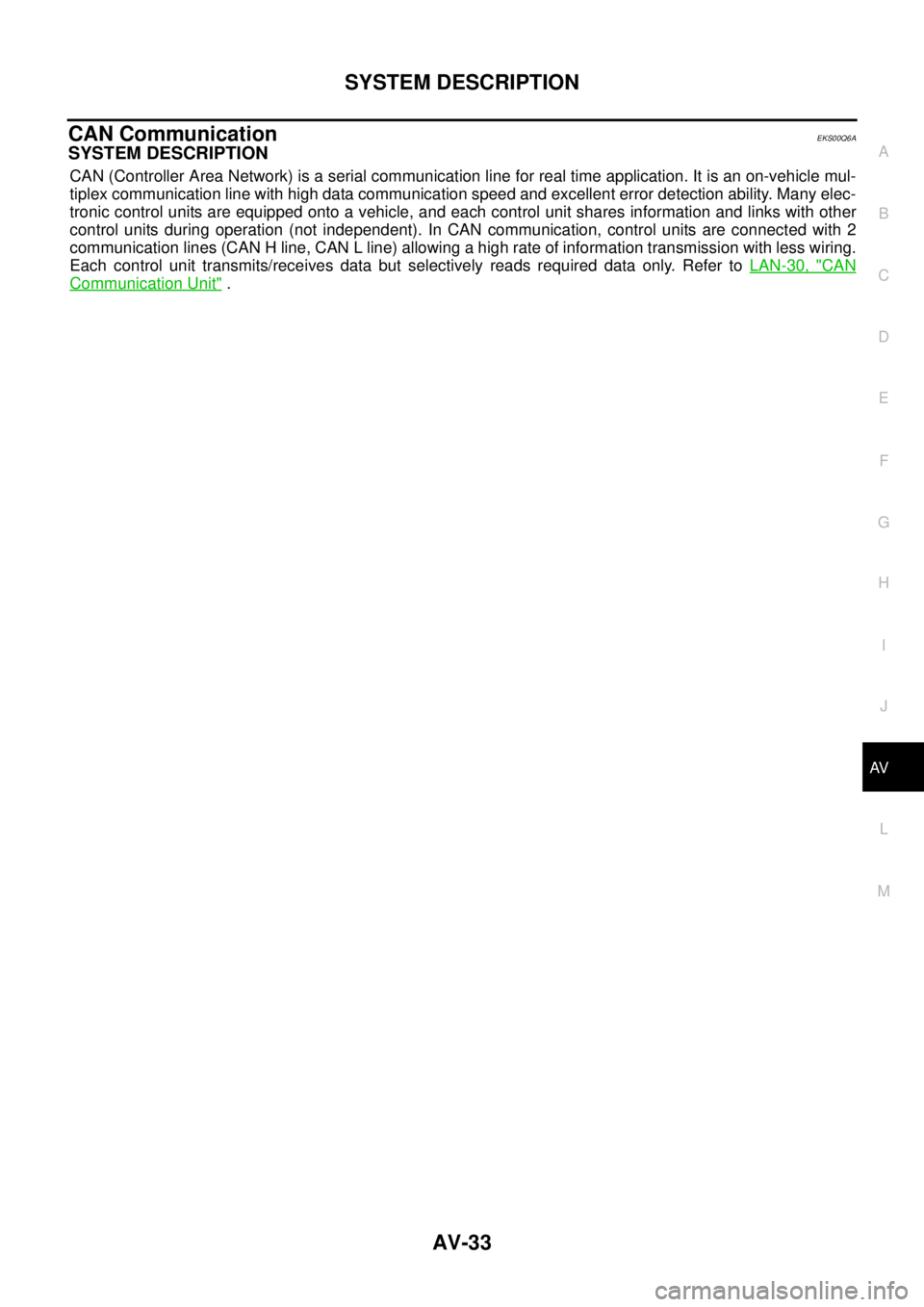
CAN CommunicationEKS00Q6A
SYSTEM DESCRIPTION
CAN (Controller Area Network) is a serial communication line for real time application. It is an on-vehicle mul-
tiplex communication line with high data communication speed and excellent error detection ability. Many elec-
tronic control units are equipped onto a vehicle, and each control unit shares information and links with other
control units during operation (not independent). In CAN communication, control units are connected with 2
communication lines (CAN H line, CAN L line) allowing a high rate of information transmission with less wiring.
Each control unit transmits/receives data but selectively reads required data only. Refer toLAN-30, "
CAN
Communication Unit".
Page 609 of 3171
POWERDOORLOCKSYSTEM
BL-25
C
D
E
F
G
H
J
K
L
MA
B
BL
Door lock indicator timer
Door lock indicator timer is designed to reacts and shut down the indicator. The default timer values are 1
minute and 30 minutes.
lWhen the lock operation is activated by keyfob or auto door lock (for further details, refer toBL-92, "Auto
Re-lock Function"), then the illuminate time is set to 1 minute.
lWhen the lock operation is activated by door lock/unlock switch, then the timer is set to 30 minutes.
NOTE:
When the 30 minutes timer is active and ignition switch is turned ON, the indicator illuminate for perma-
nently, unless ignition switch is turned OFF then timer will be reset back to 30 minutes.
CAN Communication System DescriptionEIS00D7T
CAN (Controller Area Network) is a serial communication line for real time application. It is an on-vehicle mul-
tiplex communication line with high data communication speed and excellent error detection ability. Many elec-
tronic control units are equipped onto a vehicle, and each control unit shares information and links with other
control units during operation (not independent). In CAN communication, control units are connected with 2
communication lines (CAN H line, CAN L line) allowing a high rate of information transmission with less wiring.
Each control unit transmits/receives data but selectively reads required data only.
CAN Communication UnitEIS00D7U
Refer toLAN-23, "CAN COMMUNICATION".
Page 643 of 3171
POWER DOOR LOCK — SUPER LOCK —
BL-59
C
D
E
F
G
H
J
K
L
MA
B
BL
Door Lock Warning Function
Under following conditions lock actuators will not response and buzzer warning will beeps while pressing door
lock/unlock switch in LOCK direction.
lIgnition switch is turned OFF
lMechanical key is out of ignition key cylinder
lAny door is opened (except driver side door)
Key Reminder Function
Under following conditions lock actuators will lock the door once, but then immediately unlock all doors and
buzzer warning will beeps while pressing door lock/unlock switch in LOCK direction.
lIgnition switch is turned OFF
lMechanical key is inserted in ignition key cylinder
lDriver side door is opened
Door Lock/Unlock Switch Indicator
The Door lock/unlock switch indicates door lock status. The indicator will illuminate when a lock operation is
accomplish, during this state, if any door is open, the indicator will turn OFF.
Door Lock Indicator Timer
Door lock indicator timer is designed to reacts and shut down the indicator. The default timer values are 1
minute and 30 minutes.
lWhen the lock operation is activated by keyfob or auto door lock (for further details refer toBL-92, "Auto
Re-lock Function"), then the illuminate time is set to 1 minute.
lWhen the lock operation is activated by door lock/unlock switch, then the timer is set to 30 minutes.
NOTE:
When the 30 minutes timer is active and ignition switch is turned ON, then the indicator illuminate for per-
manently unless ignition switch is turned OFF then timer will be reset back to 30 minutes.
CAN Communication System DescriptionEIS00DX1
CAN (Controller Area Network) is a serial communication line for real time application. It is an on-vehicle mul-
tiplex communication line with high data communication speed and excellent error detection ability. Many elec-
tronic control units are equipped onto a vehicle, and each control unit shares information and links with other
control units during operation (not independent). In CAN communication, control units are connected with 2
communication lines (CAN H line, CAN L line) allowing a high rate of information transmission with less wiring.
Each control unit transmits/receives data but selectively reads required data only.
CAN Communication UnitEIS00DX2
Refer toLAN-23, "CAN COMMUNICATION".
Page 829 of 3171
![NISSAN NAVARA 2005 Repair Workshop Manual CAN COMMUNICATION
BRC-7
[ABS]
C
D
E
G
H
I
J
K
L
MA
B
BRC
CAN COMMUNICATIONPFP:23710
System DescriptionEFS005TO
CAN (Controller Area Network) is a serial communication line for real time application. I NISSAN NAVARA 2005 Repair Workshop Manual CAN COMMUNICATION
BRC-7
[ABS]
C
D
E
G
H
I
J
K
L
MA
B
BRC
CAN COMMUNICATIONPFP:23710
System DescriptionEFS005TO
CAN (Controller Area Network) is a serial communication line for real time application. I](/manual-img/5/57362/w960_57362-828.png)
CAN COMMUNICATION
BRC-7
[ABS]
C
D
E
G
H
I
J
K
L
MA
B
BRC
CAN COMMUNICATIONPFP:23710
System DescriptionEFS005TO
CAN (Controller Area Network) is a serial communication line for real time application. It is an on-vehicle mul-
tiplex communication line with high data communication speed and excellent error detection ability. Many elec-
tronic control units are equipped onto a vehicle, and each control unit shares information and links with other
control units during operation (not independent). In CAN communication, control units are connected with 2
communication lines (CAN H line, CAN L line) allowing a high rate of information transmission with less wiring.
Each control unit transmits/receives data but selectively reads required data only. Refer toLAN-30, "
CAN
Communication Unit".
Page 865 of 3171

CL-1
CLUTCH
C TRANSMISSION/TRANSAXLE
CONTENTS
D
E
F
G
H
I
J
K
L
M
SECTIONCL
A
B
CL
CLUTCH
PRECAUTIONS .......................................................... 2
Service Notice or Precautions .................................. 2
PREPARATION ........................................................... 3
Special Service Tools ............................................... 3
Commercial Service Tools ........................................ 3
NOISE, VIBRATION AND HARSHNESS (NVH)
TROUBLESHOOTING ................................................ 5
NVH Troubleshooting Chart ..................................... 5
CLUTCH PEDAL ........................................................ 6
On-Vehicle Inspection and Adjustment .................... 6
Removal and Installation .......................................... 7
COMPONENTS .................................................... 7
REMOVAL ............................................................. 7
INSPECTION AFTER REMOVAL ......................... 7
INSTALLATION ..................................................... 7
CLUTCH FLUID .......................................................... 8
Air Bleeding Procedure ............................................ 8
CLUTCH MASTER CYLINDER .................................. 9
Components ............................................................. 9
Removal and Installation .......................................... 9
REMOVAL ............................................................. 9
INSTALLATION ..................................................... 9
Disassembly and Assembly ................................... 10
DISASSEMBLY ................................................... 10
INSPECTION AFTER DISASSEMBLY ............... 10
ASSEMBLY ......................................................... 10
OPERATING CYLINDER ...........................................11
Components ............................................................ 11
Removal and Installation ......................................... 11REMOVAL ........................................................... 11
INSTALLATION ................................................... 12
Disassembly and Assembly .................................... 12
DISASSEMBLY ................................................... 12
INSPECTION AFTER DISASSEMBLY ................ 12
ASSEMBLY ......................................................... 12
CLUTCH PIPING ....................................................... 13
Removal and Installation ........................................ 13
CLUTCH RELEASE MECHANISM ........................... 14
Removal and Installation ........................................ 14
COMPONENTS ................................................... 14
REMOVAL ........................................................... 14
INSPECTION AFTER REMOVAL ....................... 15
INSTALLATION ................................................... 15
CLUTCH DISC, CLUTCH COVER AND FLYWHEEL... 17
Removal and Installation ........................................ 17
COMPONENTS ................................................... 17
REMOVAL ........................................................... 17
INSPECTION AND ADJUSTMENT AFTER
REMOVAL ........................................................... 17
INSTALLATION ................................................... 18
SERVICE DATA AND SPECIFICATIONS (SDS) ...... 20
Clutch Control System ............................................ 20
Clutch Master Cylinder ........................................... 20
Clutch Operating Cylinder ...................................... 20
Clutch Disc ............................................................. 20
Clutch Cover ........................................................... 20
Clutch Pedal ........................................................... 20