Page 878 of 3171
CL-14
CLUTCH RELEASE MECHANISM
CLUTCH RELEASE MECHANISM
PFP:30502
Removal and InstallationECS00ICQ
COMPONENTS
REMOVAL
1. Remove manual transmission from the vehicle. Refer toMT-16, "Removal and Installation from Vehicle".
2. Remove release bearing sleeve assembly, holder spring and withdrawal lever from inside clutch housing.
3. Remove dust cover.
4. Remove snap spring from withdrawal lever.
5. Remove release bearing from release bearing sleeve using a
puller.
1. Holder spring 2. Release bearing sleeve 3. Release bearing
4. Snap spring 5. Dust cover 6. Withdrawal lever
PCIB1615E
CLA0013D
Page 879 of 3171

CLUTCH RELEASE MECHANISM
CL-15
D
E
F
G
H
I
J
K
L
MA
B
CL
INSPECTION AFTER REMOVAL
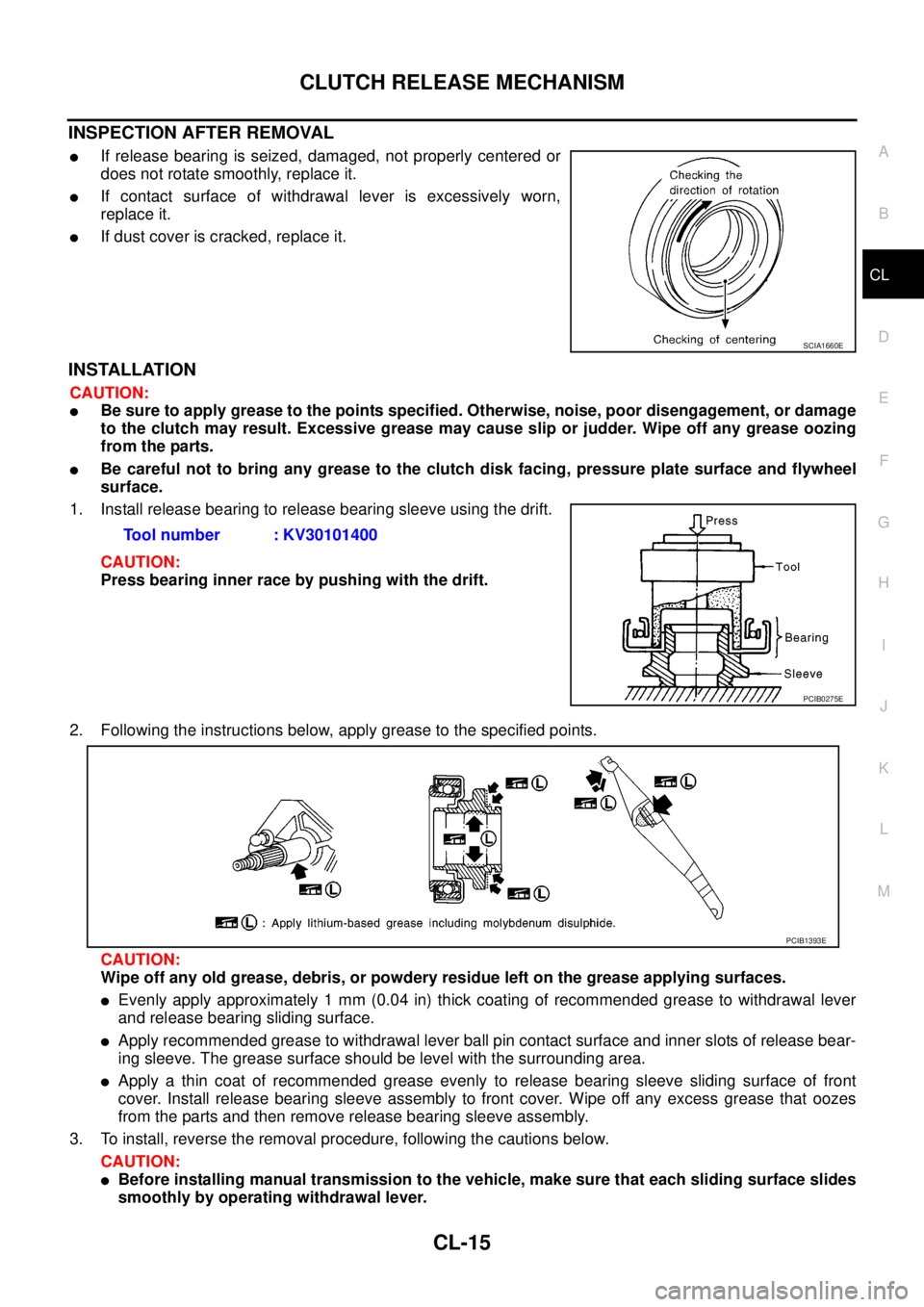
lIf release bearing is seized, damaged, not properly centered or
does not rotate smoothly, replace it.
lIf contact surface of withdrawal lever is excessively worn,
replace it.
lIf dust cover is cracked, replace it.
INSTALLATION
CAUTION:
lBe sure to apply grease to the points specified. Otherwise, noise, poor disengagement, or damage
to the clutch may result. Excessive grease may cause slip or judder. Wipe off any grease oozing
from the parts.
lBe careful not to bring any grease to the clutch disk facing, pressure plate surface and flywheel
surface.
1. Install release bearing to release bearing sleeve using the drift.
CAUTION:
Press bearing inner race by pushing with the drift.
2. Following the instructions below, apply grease to the specified points.
CAUTION:
Wipe off any old grease, debris, or powdery residue left on the grease applying surfaces.
lEvenly apply approximately 1 mm (0.04 in) thick coating of recommended grease to withdrawal lever
and release bearing sliding surface.
lApply recommended grease to withdrawal lever ball pin contact surface and inner slots of release bear-
ing sleeve. The grease surface should be level with the surrounding area.
lApply a thin coat of recommended grease evenly to release bearing sleeve sliding surface of front
cover. Install release bearing sleeve assembly to front cover. Wipe off any excess grease that oozes
from the parts and then remove release bearing sleeve assembly.
3. To install, reverse the removal procedure, following the cautions below.
CAUTION:
lBefore installing manual transmission to the vehicle, make sure that each sliding surface slides
smoothly by operating withdrawal lever.
SCIA1660E
Tool number : KV30101400
PCIB0275E
PCIB1393E
Page 881 of 3171

CLUTCH DISC, CLUTCH COVER AND FLYWHEEL
CL-17
D
E
F
G
H
I
J
K
L
MA
B
CL
CLUTCH DISC, CLUTCH COVER AND FLYWHEELPFP:30100
Removal and InstallationECS00ICR
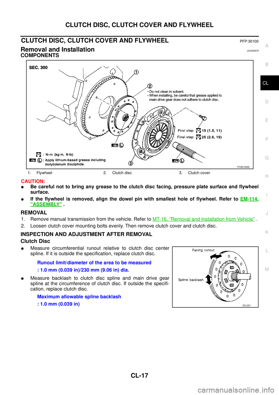
COMPONENTS
CAUTION:
lBe careful not to bring any grease to the clutch disc facing, pressure plate surface and flywheel
surface.
lIf the flywheel is removed, align the dowel pin with smallest hole of flywheel. Refer toEM-114,
"ASSEMBLY".
REMOVAL
1. Remove manual transmission from the vehicle. Refer toMT-16, "Removal and Installation from Vehicle".
2. Loosen clutch cover mounting bolts evenly. Then remove clutch cover and clutch disc.
INSPECTION AND ADJUSTMENT AFTER REMOVAL
Clutch Disc
lMeasure circumferential runout relative to clutch disc center
spline. If it is outside the specification, replace clutch disc.
lMeasure backlash to clutch disc spline and main drive gear
spline at the circumference of clutch disc. If outside the specifi-
cation, replace clutch disc.
1. Flywheel 2. Clutch disc 3. Clutch cover
PCIB1394E
Runout limit/diameter of the area to be measured
: 1.0 mm (0.039 in)/230 mm (9.06 in) dia.
Maximum allowable spline backlash
: 1.0 mm (0.039 in)
SCL221
Page 883 of 3171
CLUTCH DISC, CLUTCH COVER AND FLYWHEEL
CL-19
D
E
F
G
H
I
J
K
L
MA
B
CL
2. Install clutch disc using the clutch aligning bar.
3. Install clutch cover. Pre-tighten clutch cover mounting bolts.
4. Tighten clutch cover mounting bolts evenly in two steps in the
order shown in the figure. Refer toCL-17, "
COMPONENTS".
5. Install manual transmission. Refer toMT-16, "
Removal and
Installation from Vehicle". Tool number : KV30100100
PCIB1630E
Page 975 of 3171
CAN COMMUNICATION
DI-65
C
D
E
F
G
H
I
J
L
MA
B
DI
CAN COMMUNICATIONPFP:23710
System DescriptionEKS00MHE
CAN (Controller Area Network) is a serial communication line for real time application. It is an on-vehicle mul-
tiplex communication line with high data communication speed and excellent error detection ability. Many elec-
tronic control units are equipped onto a vehicle, and each control unit shares information and links with other
control units during operation (not independent). In CAN communication, control units are connected with 2
communication lines (CAN H line, CAN L line) allowing a high rate of information transmission with less wiring.
Each control unit transmits/receives data but selectively reads required data only.
CAN Communication UnitEKS00MHF
Refer toLAN-30, "CAN Communication Unit"in “LAN SYSTEM”.
Page 1002 of 3171
EC-22
ENGINE CONTROL SYSTEM
CAN Communication
EBS01KCJ
SYSTEM DESCRIPTION
CAN (Controller Area Network) is a serial communication line for real time application. It is an on-vehicle mul-
tiplex communication line with high data communication speed and excellent error detection ability. Many elec-
tronic control units are equipped onto a vehicle, and each control unit shares information and links with other
control units during operation (not independent). In CAN communication, control units are connected with 2
communication lines (CAN H line, CAN L line) allowing a high rate of information transmission with less wiring.
Each control unit transmits/receives data but selectively reads required data only.
Refer toLAN-30, "
CAN Communication Unit", about CAN communication for detail.
Page 1059 of 3171

DTC U1000 CAN COMMUNICATION LINE
EC-79
C
D
E
F
G
H
I
J
K
L
MA
EC
DTC U1000 CAN COMMUNICATION LINEPFP:23710
DescriptionEBS01KDA
CAN (Controller Area Network) is a serial communication line for real time application. It is an on-vehicle mul-
tiplex communication line with high data communication speed and excellent error detection ability. Many elec-
tronic control units are equipped onto a vehicle, and each control unit shares information and links with other
control units during operation (not independent). In CAN communication, control units are connected with 2
communication lines (CAN H line, CAN L line) allowing a high rate of information transmission with less wiring.
Each control unit transmits/receives data but selectively reads required data only.
On Board Diagnosis LogicEBS01KDB
The MI will not light up for this self-diagnosis.
DTC Confirmation ProcedureEBS01KDC
NOTE:
If DTC Confirmation Procedure has been previously conducted, always turn ignition switch OFF and wait at
least 10 seconds before conducting the next test.
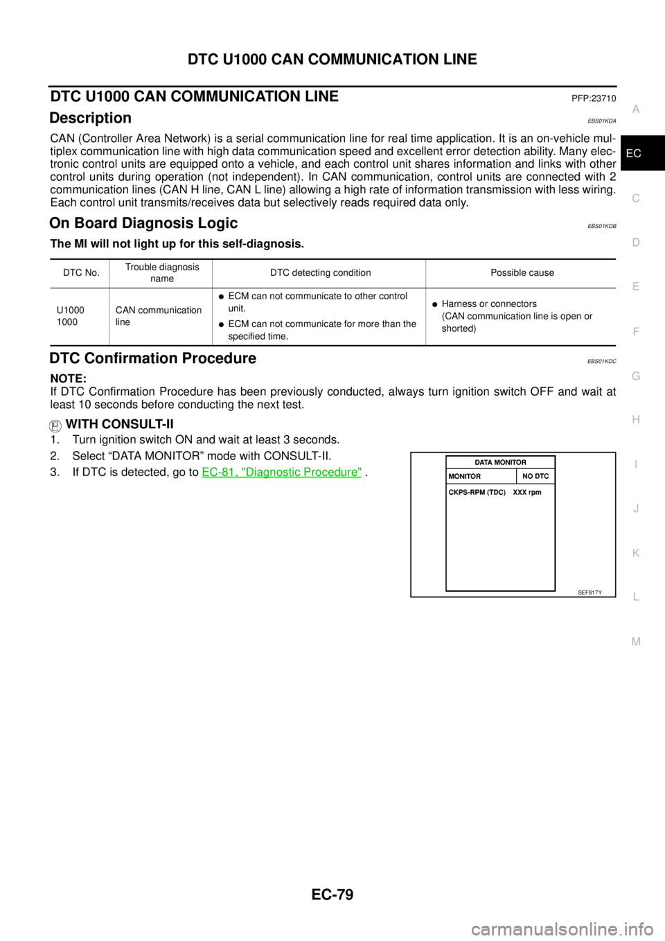
WITH CONSULT-II
1. Turn ignition switch ON and wait at least 3 seconds.
2. Select “DATA MONITOR” mode with CONSULT-II.
3. If DTC is detected, go toEC-81, "
Diagnostic Procedure".
DTC No.Trouble diagnosis
nameDTC detecting condition Possible cause
U1000
1000CAN communication
line
lECM can not communicate to other control
unit.
lECM can not communicate for more than the
specified time.
lHarness or connectors
(CAN communication line is open or
shorted)
SEF817Y
Page 1419 of 3171

OIL PAN AND OIL STRAINER
EM-37
C
D
E
F
G
H
I
J
K
L
MA
EM
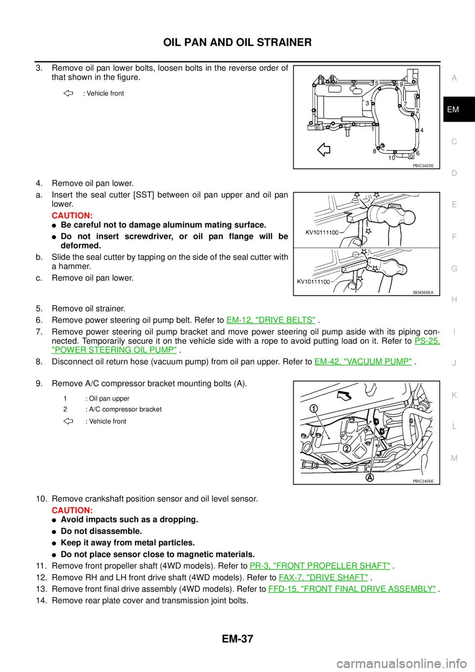
3. Remove oil pan lower bolts, loosen bolts in the reverse order of
that shown in the figure.
4. Remove oil pan lower.
a. Insert the seal cutter [SST] between oil pan upper and oil pan
lower.
CAUTION:
lBe careful not to damage aluminum mating surface.
lDo not insert screwdriver, or oil pan flange will be
deformed.
b. Slide the seal cutter by tapping on the side of the seal cutter with
a hammer.
c. Remove oil pan lower.
5. Remove oil strainer.
6. Remove power steering oil pump belt. Refer toEM-12, "
DRIVE BELTS".
7. Remove power steering oil pump bracket and move power steering oil pump aside with its piping con-
nected. Temporarily secure it on the vehicle side with a rope to avoid putting load on it. Refer toPS-25,
"POWER STEERING OIL PUMP".
8. Disconnect oil return hose (vacuum pump) from oil pan upper. Refer toEM-42, "
VACUUM PUMP".
9. Remove A/C compressor bracket mounting bolts (A).
10. Remove crankshaft position sensor and oil level sensor.
CAUTION:
lAvoid impacts such as a dropping.
lDo not disassemble.
lKeep it away from metal particles.
lDo not place sensor close to magnetic materials.
11. Remove front propeller shaft (4WD models). Refer toPR-3, "
FRONT PROPELLER SHAFT".
12. Remove RH and LH front drive shaft (4WD models). Refer toFAX-7, "
DRIVE SHAFT".
13. Remove front final drive assembly (4WD models). Refer toFFD-15, "
FRONT FINAL DRIVE ASSEMBLY".
14. Remove rear plate cover and transmission joint bolts.
: Vehicle front
PBIC3425E
SEM365EA
1 : Oil pan upper
2 : A/C compressor bracket
: Vehicle front
PBIC3426E