Page 2717 of 3171
![NISSAN NAVARA 2005 Repair Workshop Manual RFD-14
[WITH LIMITED SLIP DIFFERENTIAL]
REAR FINAL DRIVE ASSEMBLY
REAR FINAL DRIVE ASSEMBLY
PFP:38300
Removal and InstallationEDS00398
REMOVAL
1. Remove the rear propeller shaft. Refer toPR-8, "Remova NISSAN NAVARA 2005 Repair Workshop Manual RFD-14
[WITH LIMITED SLIP DIFFERENTIAL]
REAR FINAL DRIVE ASSEMBLY
REAR FINAL DRIVE ASSEMBLY
PFP:38300
Removal and InstallationEDS00398
REMOVAL
1. Remove the rear propeller shaft. Refer toPR-8, "Remova](/manual-img/5/57362/w960_57362-2716.png)
RFD-14
[WITH LIMITED SLIP DIFFERENTIAL]
REAR FINAL DRIVE ASSEMBLY
REAR FINAL DRIVE ASSEMBLY
PFP:38300
Removal and InstallationEDS00398
REMOVAL
1. Remove the rear propeller shaft. Refer toPR-8, "Removal and Installation".
lPlug rear end of transmission or transfer.
2. Remove the axle shafts and back plate and torque members. Refer toRAX-7, "
Removal and Installation".
3. Disconnect the following components from the rear final drive.
lABS sensor wire harness
lRear cable (LH) and rear cable (RH)
lBrake hoses and brake tube
CAUTION:
Position the wire harness, cable and hoses away from the final drive assembly. Failure to do so
may result in components being damaged during rear axle assembly removal.
4. Support the rear final drive using a suitable jack.
5. Remove rear shock absorber lower bolts. Refer toRSU-6, "
Removal and Installation".
6. Remove leaf spring U-bolt nuts. Refer toRSU-7, "
Removal and Installation".
WARNING:
Support the rear final drive assembly using suitable jack before removing leaf spring U-bolt nuts.
7. Remove rear final drive assembly using suitable jack.
INSTALLATION
Installation is the reverse order of removal.
lWhen oil leaks while removing rear final drive assembly, check oil level after the installation. Refer to
RFD-9, "
Checking Differential Gear Oil".
lRefill brake fluid and bleed the air from the brake system. Refer toBR-11, "Bleeding Brake System".
Page 2746 of 3171
![NISSAN NAVARA 2005 Repair Workshop Manual DIFFERENTIAL LOCK SYSTEM
RFD-43
[WITH ELECTRONIC LOCKING DIFFERENTIAL]
C
E
F
G
H
I
J
K
L
MA
B
RFD
System DiagramEDS003AS
COMPONENTS FUNCTION DESCRIPTION
CAN CommunicationEDS003AT
SYSTEM DESCRIPTION
CA NISSAN NAVARA 2005 Repair Workshop Manual DIFFERENTIAL LOCK SYSTEM
RFD-43
[WITH ELECTRONIC LOCKING DIFFERENTIAL]
C
E
F
G
H
I
J
K
L
MA
B
RFD
System DiagramEDS003AS
COMPONENTS FUNCTION DESCRIPTION
CAN CommunicationEDS003AT
SYSTEM DESCRIPTION
CA](/manual-img/5/57362/w960_57362-2745.png)
DIFFERENTIAL LOCK SYSTEM
RFD-43
[WITH ELECTRONIC LOCKING DIFFERENTIAL]
C
E
F
G
H
I
J
K
L
MA
B
RFD
System DiagramEDS003AS
COMPONENTS FUNCTION DESCRIPTION
CAN CommunicationEDS003AT
SYSTEM DESCRIPTION
CAN (Controller Area Network) is a serial communication line for real time application. It is an on-vehicle mul-
tiplex communication line with high data communication speed and excellent error detection ability. Many elec-
tronic control units are equipped onto a vehicle, and each control unit shares information and links with other
control units during operation (not independent). In CAN communication, control units are connected with 2
communication lines (CAN H line, CAN L line) allowing a high rate of information transmission with less wiring.
Each control unit transmits/receives data but selectively reads required data only.
For details, refer toDI-65, "
CAN Communication Unit".
SDIA2500E
Component parts Function
Differential lock control unit
lControls differential lock solenoid and switches differential lock/unlock.
lAs a fail-safe function, differential lock disengages, if malfunction is detected in differential lock
system.
Differential lock solenoid Controls pressure plate by current from differential lock control unit.
Differential lock position switch Detects that differential is lock or unlock condition.
Differential lock mode switch Able to select differential lock or unlock.
DIFF LOCK indicator lamp Illuminates that differential is in lock or lock standby condition.
ABS actuator and electric unit
(control unit)Transmits the following signals via CAN communication to differential lock control unit.
lVehicle speed signal
Transfer control unitTransmits the following signal via CAN communication to differential lock control unit.
l4WD shift switch signal
Page 2784 of 3171
![NISSAN NAVARA 2005 Repair Workshop Manual REAR FINAL DRIVE ASSEMBLY
RFD-81
[WITH ELECTRONIC LOCKING DIFFERENTIAL]
C
E
F
G
H
I
J
K
L
MA
B
RFD
REAR FINAL DRIVE ASSEMBLYPFP:38300
Removal and InstallationEDS003BF
REMOVAL
1. Remove the rear propel NISSAN NAVARA 2005 Repair Workshop Manual REAR FINAL DRIVE ASSEMBLY
RFD-81
[WITH ELECTRONIC LOCKING DIFFERENTIAL]
C
E
F
G
H
I
J
K
L
MA
B
RFD
REAR FINAL DRIVE ASSEMBLYPFP:38300
Removal and InstallationEDS003BF
REMOVAL
1. Remove the rear propel](/manual-img/5/57362/w960_57362-2783.png)
REAR FINAL DRIVE ASSEMBLY
RFD-81
[WITH ELECTRONIC LOCKING DIFFERENTIAL]
C
E
F
G
H
I
J
K
L
MA
B
RFD
REAR FINAL DRIVE ASSEMBLYPFP:38300
Removal and InstallationEDS003BF
REMOVAL
1. Remove the rear propeller shaft. Refer toPR-8, "Removal and Installation".
lPlug rear end of transmission or transfer.
2. Remove the axle shafts and back plate and torque members. Refer toRAX-7, "
Removal and Installation".
3. Disconnect the following components from the rear final drive.
lABS sensor wire harness
lRear cable (LH) and rear cable (RH)
lBrake hoses and brake tube
lDifferential lock position switch harness connector
lDifferential lock solenoid harness connector
CAUTION:
Position the wire harness, cable and hoses away from the final drive assembly. Failure to do so
may result in components being damaged during rear axle assembly removal.
4. Support the rear final drive using a suitable jack.
5. Remove rear shock absorber lower bolts. Refer toRSU-6, "
Removal and Installation".
6. Remove leaf spring U-bolt nuts. Refer toRSU-7, "
Removal and Installation".
WARNING:
Support the rear final drive assembly using suitable jack before removing leaf spring U-bolt nuts.
7. Remove rear final drive assembly using suitable jack.
INSTALLATION
Installation is the reverse order of removal.
lWhen oil leaks while removing rear final drive assembly, check oil level after the installation. Refer to
RFD-40, "
Checking Differential Gear Oil".
lRefill brake fluid and bleed the air from the brake system. Refer toBR-11, "Bleeding Brake System".
lAfter the installation, check DIFF LOCK indicator lamp. Refer toRFD-33, "Precautions for Differential
Case Assembly and Differential Lock Control Unit Replacement".
Page 2864 of 3171
STARTING SYSTEM
SC-31
C
D
E
F
G
H
I
J
L
MA
B
SC
Removal and InstallationEKS00MZP
REMOVAL
1. Disconnect negative battery cable.
2. Remove engine under covers.
3. Disconnect S terminal and B terminal from starter motor.
4. Remove starter motor mounting bolts (two).
5. Remove starter motor from bottom side the vehicle.
INSTALLATION
Install in the reverse order of removal.
(M8T76071ZE)
1. Starter motor assembly 2. Rear plate 3. Transmission case
MKIB1991E
B terminal nut :
: 7.35 - 9.81 N·m (0.75 - 1.0 kg-m, 65 - 87 in-lb)
S terminal nut :
:3.0-5.0N·m(0.3-0.5kg-m,27-44in-lb)
Page 2985 of 3171

TF-18
4WD SYSTEM
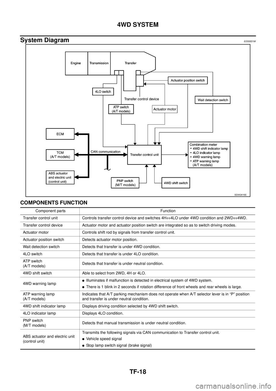
System Diagram
EDS0031M
COMPONENTS FUNCTION
SDIA3416E
Component parts Function
Transfer control unit Controls transfer control device and switches 4HÛ4LO under 4WD condition and 2WDÛ4WD.
Transfer control device Actuator motor and actuator position switch are integrated so as to switch driving modes.
Actuator motor Controls shift rod by signals from transfer control unit.
Actuator position switch Detects actuator motor position.
Wait detection switch Detects that transfer is under 4WD condition.
4LO switch Detects that transfer is under 4LO condition.
AT P s w i t c h
(A/T models)Detects that transfer is under neutral condition.
4WD shift switch Able to select from 2WD, 4H or 4LO.
4WD warning lamp
lIlluminates if malfunction is detected in electrical system of 4WD system.
lThere is 1 blink in 2 seconds if rotation difference of front wheels and rear wheels is large.
ATP warning lamp
(A/T models)Indicates that A/T parking mechanism does not operate when A/T selector lever is in “P” position
and transfer is under neutral condition.
4WD shift indicator lamp Displays driving condition selected by 4WD shift switch.
4LO indicator lamp Displays 4LO condition.
PNP switch
(M/T models)Detects that manual transmission is under neutral condition.
ABS actuator and electric unit
(control unit)Transmits the following signals via CAN communication to Transfer control unit.
lVehicle speed signal
lStop lamp switch signal (brake signal)
Page 2986 of 3171

4WD SYSTEM
TF-19
C
E
F
G
H
I
J
K
L
MA
B
TF
CAN CommunicationEDS0031N
SYSTEM DESCRIPTION
CAN (Controller Area Network) is a serial communication line for real time application. It is an on-vehicle mul-
tiplex communication line with high data communication speed and excellent error detection ability. Many elec-
tronic control units are equipped onto a vehicle, and each control unit shares information and links with other
control units during operation (not independent). In CAN communication, control units are connected with 2
communication lines (CAN H line, CAN L line) allowing a high rate of information transmission with less wiring.
Each control unit transmits/receives data but selectively reads required data only.
For details, refer toLAN-23, "
CAN COMMUNICATION".
TCM
(A/T models)Transmits the following signal via CAN communication to Transfer control unit.lOutput shaft revolution signal
lA/T position indicator signal (PNP switch signal)
ECMTransmits engine speed signal via CAN communication to Transfer control unit.
lEngine speed signal Component parts Function
Page 3078 of 3171

TRANSFER ASSEMBLY
TF-111
C
E
F
G
H
I
J
K
L
MA
B
TF
TRANSFER ASSEMBLYPFP:33100
Removal and InstallationEDS0032O
REMOVAL
1. Switch 4WD shift switch to 2WD and set transfer assembly to 2WD.
2. Remove the drain plug and gasket. Drain the fluid. Refer toTF-12, "
Replacement".
3. Remove the transmission undercover.
4. Remove the main muffler. Refer toEX-3, "
Removal and Installation".
5. Remove the front and rear propeller shafts. Refer toPR-4, "
Removal and Installation"(front) andPR-8,
"Removal and Installation"(rear).
CAUTION:
Do not damage spline, sleeve yoke and rear oil seal when removing rear propeller shaft.
NOTE:
Insert a plug into the rear oil seal after removing the rear propeller shaft.
6. Remove transmission bolts. Refer toAT-247, "
Removal and Installation"(A/T models) orMT-16,
"Removal and Installation from Vehicle"(M/T models).
7. Position two suitable jacks under the transmission and transfer assembly.
8. Remove the transmission crossmember. Refer toAT- 2 4 7 , "
Removal and Installation"(A/T models) orMT-
16, "Removal and Installation from Vehicle"(M/T models).
WARNING:
Support transmission and transfer assembly using two suitable jacks while removing transmis-
sion crossmember.
9. Disconnect the electrical connectors from the following:
lAT P s w i t c h
l4LO switch
lWait detection switch
lTransfer control device
10. Disconnect each air breather hose from the following. Refer toTF-107, "
A/T MODELS"(A/T models) or
TF-109, "
M/T MODELS"(M/T models).
lTransfer control device
lBreather tube (transfer)
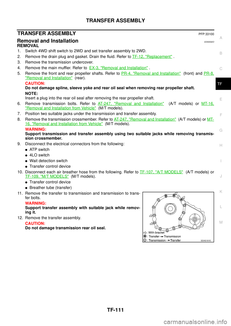
11. Remove the transfer to transmission and transmission to trans-
fer bolts.
WARNING:
Support transfer assembly with suitable jack while remov-
ing it.
12. Remove the transfer assembly.
CAUTION:
Do not damage transmission rear oil seal.
SDIA3181E