Page 2356 of 3171
TRANSMISSION ASSEMBLY
MT-39
D
E
F
G
H
I
J
K
L
MA
B
MT
26. Press out 3rd gear bushing using a puller.
SCIA1534E
Page 2357 of 3171
MT-40
TRANSMISSION ASSEMBLY
INSPECTION AFTER DISASSEMBLY
Shift Control
If the contact surface on striking lever, fork rod, shift fork, etc., has
excessive wear, abrasion, bend, or any other damage, replace the
components.
Gear and Shaft
If the contact surface on each gear, mainshaft, main drive gear, and
counter gear, etc., has damage, peeling, abrasion, dent, bent, or any
other damage, replace the components.
PCIB1245E
SCIA1680E
PCIB1246E
Page 2358 of 3171

TRANSMISSION ASSEMBLY
MT-41
D
E
F
G
H
I
J
K
L
MA
B
MT
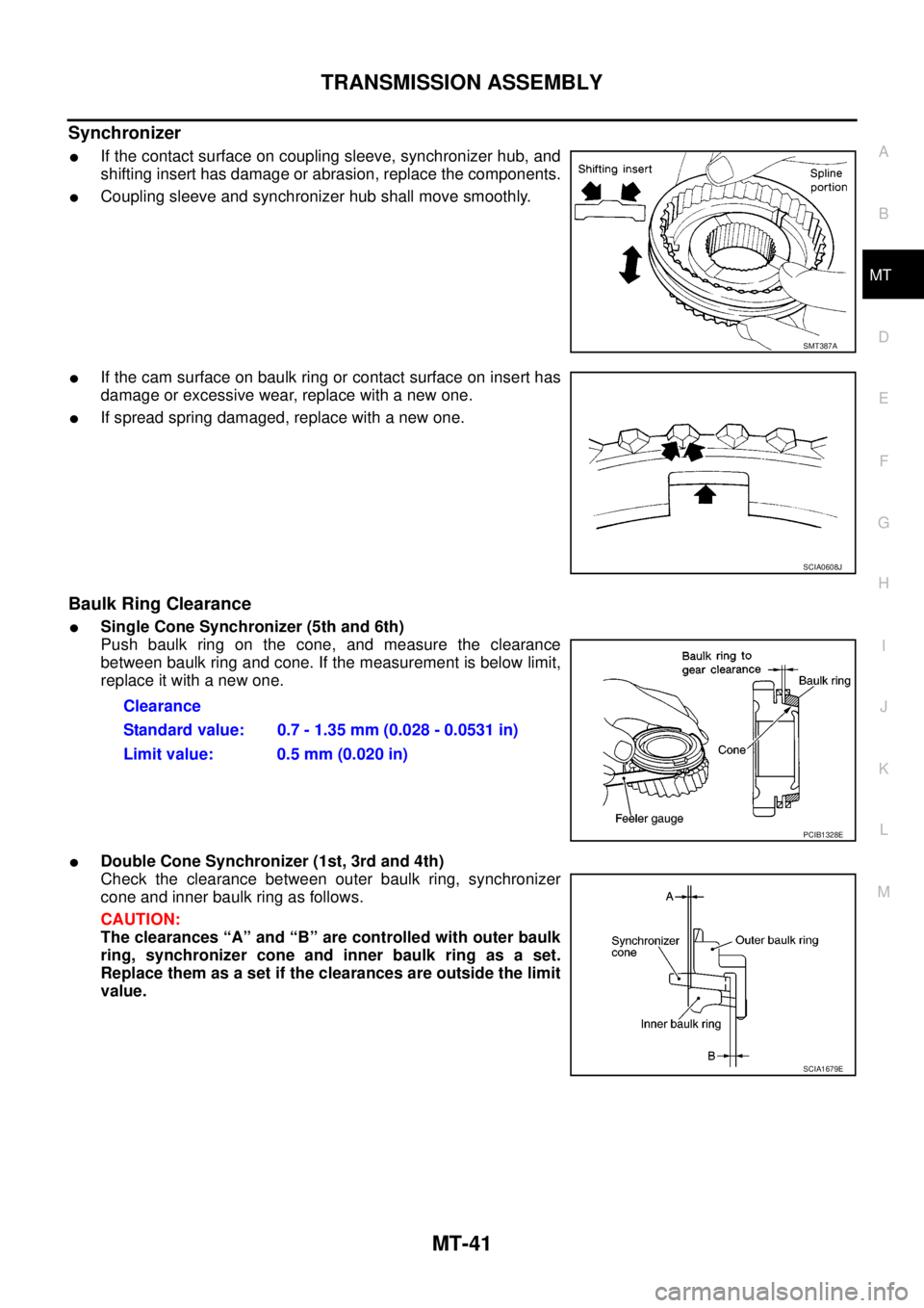
Synchronizer
lIf the contact surface on coupling sleeve, synchronizer hub, and
shifting insert has damage or abrasion, replace the components.
lCoupling sleeve and synchronizer hub shall move smoothly.
lIf the cam surface on baulk ring or contact surface on insert has
damage or excessive wear, replace with a new one.
lIf spread spring damaged, replace with a new one.
Baulk Ring Clearance
lSingle Cone Synchronizer (5th and 6th)
Push baulk ring on the cone, and measure the clearance
between baulk ring and cone. If the measurement is below limit,
replace it with a new one.
lDouble Cone Synchronizer (1st, 3rd and 4th)
Check the clearance between outer baulk ring, synchronizer
cone and inner baulk ring as follows.
CAUTION:
The clearances “A” and “B” are controlled with outer baulk
ring, synchronizer cone and inner baulk ring as a set.
Replace them as a set if the clearances are outside the limit
value.
SMT387A
SCIA0608J
Clearance
Standard value: 0.7 - 1.35 mm (0.028 - 0.0531 in)
Limit value: 0.5 mm (0.020 in)
PCIB1328E
SCIA1679E
Page 2359 of 3171

MT-42
TRANSMISSION ASSEMBLY
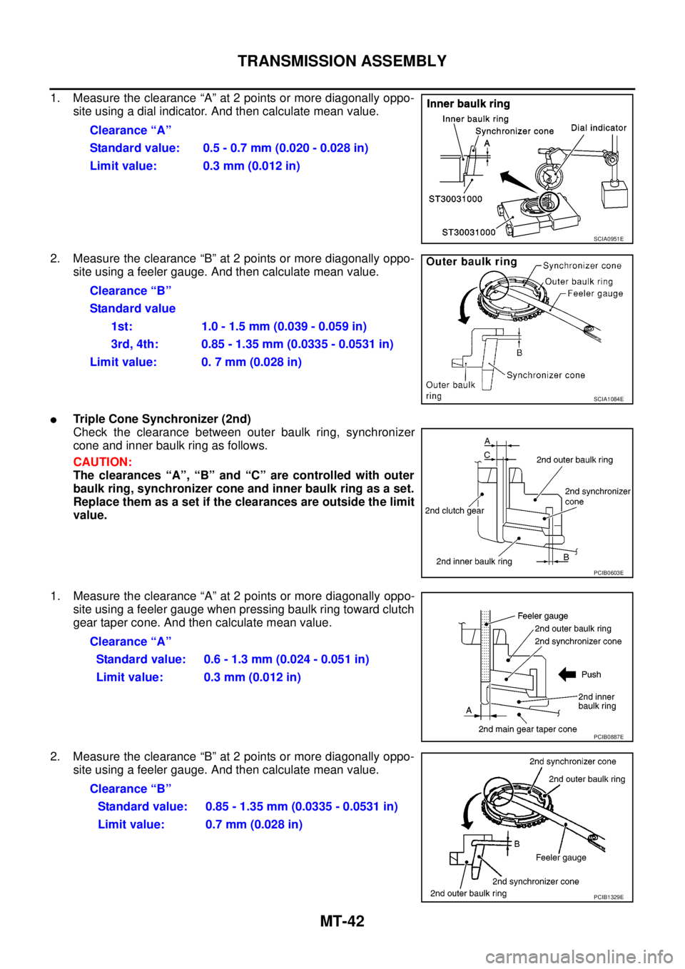
1. Measure the clearance “A” at 2 points or more diagonally oppo-
site using a dial indicator. And then calculate mean value.
2. Measure the clearance “B” at 2 points or more diagonally oppo-
site using a feeler gauge. And then calculate mean value.
lTriple Cone Synchronizer (2nd)
Check the clearance between outer baulk ring, synchronizer
cone and inner baulk ring as follows.
CAUTION:
The clearances “A”, “B” and “C” are controlled with outer
baulk ring, synchronizer cone and inner baulk ring as a set.
Replace them as a set if the clearances are outside the limit
value.
1. Measure the clearance “A” at 2 points or more diagonally oppo-
site using a feeler gauge when pressing baulk ring toward clutch
gear taper cone. And then calculate mean value.
2. Measure the clearance “B” at 2 points or more diagonally oppo-
site using a feeler gauge. And then calculate mean value.Clearance “A”
Standard value: 0.5 - 0.7 mm (0.020 - 0.028 in)
Limit value: 0.3 mm (0.012 in)
SCIA0951E
Clearance “B”
Standard value
1st: 1.0-1.5mm(0.039-0.059in)
3rd, 4th: 0.85 - 1.35 mm (0.0335 - 0.0531 in)
Limit value: 0. 7 mm (0.028 in)
SCIA1084E
PCIB0603E
Clearance “A”
Standard value: 0.6 - 1.3 mm (0.024 - 0.051 in)
Limit value: 0.3 mm (0.012 in)
PCIB0887E
Clearance “B”
Standard value: 0.85 - 1.35 mm (0.0335 - 0.0531 in)
Limit value: 0.7 mm (0.028 in)
PCIB1329E
Page 2360 of 3171
TRANSMISSION ASSEMBLY
MT-43
D
E
F
G
H
I
J
K
L
MA
B
MT
3. Measure the clearance “C” at 2 points or more diagonally oppo-
site using a feeler gauge when pressing baulk ring toward clutch
gear taper cone. And then calculate mean value.
lReverse Synchronizer
Push baulk ring on the cone, and measure the clearance
between baulk ring and cone. If the measurement is below limit,
replace it with a new one.
Bearing
If the bearing does not rotate smoothly or the contact surface on ball
or race is damaged or peeled, replace with new ones.Clearance “C”
Standard value: 0.7 - 1.25 mm (0.028 - 0.0492 in)
Limit value: 0.3 mm (0.012 in)
PCIB0888E
Clearance
Standard value: 0.75 - 1.2 mm (0.0295 - 0.047 in)
Limit value: 0.5 mm (0.020 in)
PCIB1328E
SMT418A
Page 2361 of 3171
MT-44
TRANSMISSION ASSEMBLY
ASSEMBLY
Gear Components
1. Install 5th-6th synchronizer hub assembly according to the following.
a. Install 5th-6th coupling sleeve to 5th-6th synchronizer hub.
CAUTION:
lDo not reuse 5th-6th synchronizer hub and 5th-6th coupling sleeve.
lReplace 5th-6th synchronizer hub and 5th-6th coupling sleeve as a set.
lBe careful with the orientation 5th-6th coupling sleeve.
lBe careful with the orientation 5th-6th synchronizer hub.
b. Install shifting inserts and spread springs to 5th-6th synchronizer
hub.
CAUTION:
lDo not install spread spring hook onto the same shifting
insert.
lBe careful with the shape of reserve shifting insert to
avoid misemploy.
PCIB1247E
PCIB1248E
SCIA1600E
PCIB0608E
Page 2362 of 3171
TRANSMISSION ASSEMBLY
MT-45
D
E
F
G
H
I
J
K
L
MA
B
MT
c. Press in 5th-6th synchronizer hub assembly, 6th baulk ring, 6th
main gear and 6th needle bearing using the inserter.
CAUTION:
lApply gear oil to 6th baulk ring and 6th needle bearing.
lBe careful with the orientation 5th-6th coupling sleeve.
NOTE:
5th and 6th baulk rings have three spaces that four gear teeth
are missing as shown in the figure.
2. Select and install a snap ring so that the end play comes within
the standard value. Refer toMT-68, "
Snap Rings".
CAUTION:
Do not reuse snap ring.
3. Install 1st-2nd synchronizer hub assembly according to the following.
a. Install 1st-2nd coupling sleeve to 1st-2nd synchronizer hub.
CAUTION:
lDo not reuse 1st-2nd coupling sleeve and 1st-2nd synchronizer hub.
lReplace 1st-2nd synchronizer hub and 1st-2nd coupling sleeve as a set.
lBe careful with the orientation 1st-2nd coupling sleeve.
PCIB1409E
PCIB1330E
End play: 0 - 0.10 mm (0 - 0.004 in)
PCIB0609E
PCIB1250E
Page 2363 of 3171
MT-46
TRANSMISSION ASSEMBLY
lBe careful with the orientation 1st-2nd synchronizer hub.
b. Install spread springs and shifting inserts to 1st-2nd synchro-
nizer hub.
CAUTION:
lDo not install spread spring hook onto the same shifting
insert.
lBe careful with the shape of reverse shifting insert to
avoid misassembly.
c. Press in 1st-2nd synchronizer hub assembly, 2nd inner baulk
ring, 2nd synchronizer cone, 2nd outer baulk ring, 2nd main
gear and 2nd needle bearing using the support ring.
CAUTION:
lApply gear oil to 2nd needle bearing, 2nd inner baulk
ring, 2nd synchronizer cone, 2nd outer baulk ring and
1st-2nd synchronizer hub spline of mainshaft.
lReplace 2nd inner baulk ring, 2nd synchronizer cone and
2nd outer baulk ring as a set.
lBe careful with the orientation 1st-2nd coupling sleeve.
PCIB1251E
SCIA1600E
PCIB0608E
PCIB1410E