2005 NISSAN NAVARA transmission
[x] Cancel search: transmissionPage 1494 of 3171
EM-112
CYLINDER BLOCK
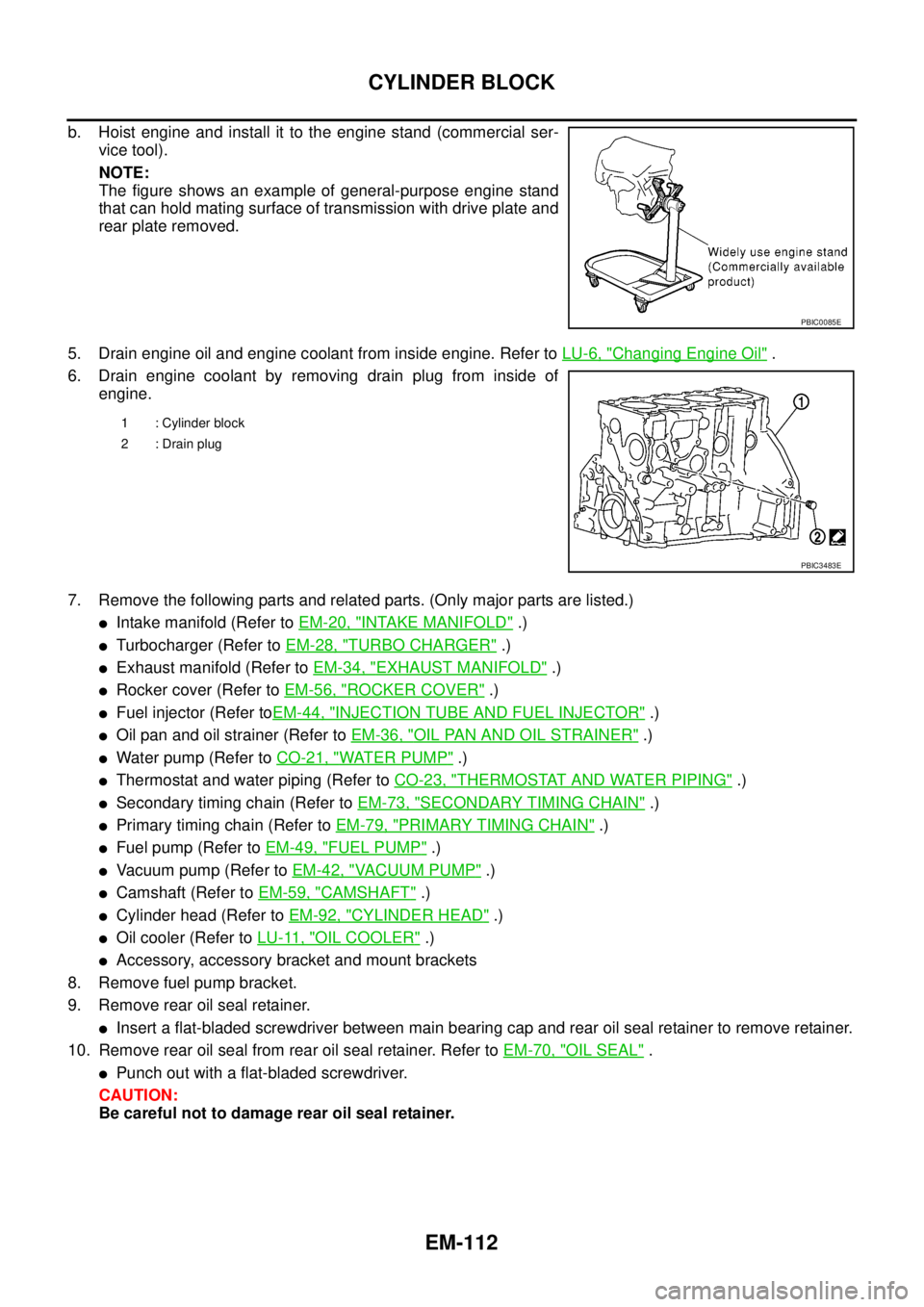
b. Hoist engine and install it to the engine stand (commercial ser-
vice tool).
NOTE:
The figure shows an example of general-purpose engine stand
that can hold mating surface of transmission with drive plate and
rear plate removed.
5. Drain engine oil and engine coolant from inside engine. Refer toLU-6, "
Changing Engine Oil".
6. Drain engine coolant by removing drain plug from inside of
engine.
7. Remove the following parts and related parts. (Only major parts are listed.)
lIntake manifold (Refer toEM-20, "INTAKE MANIFOLD".)
lTurbocharger (Refer toEM-28, "TURBO CHARGER".)
lExhaust manifold (Refer toEM-34, "EXHAUST MANIFOLD".)
lRocker cover (Refer toEM-56, "ROCKER COVER".)
lFuel injector (Refer toEM-44, "INJECTION TUBE AND FUEL INJECTOR".)
lOil pan and oil strainer (Refer toEM-36, "OIL PAN AND OIL STRAINER".)
lWater pump (Refer toCO-21, "WATER PUMP".)
lThermostat and water piping (Refer toCO-23, "THERMOSTAT AND WATER PIPING".)
lSecondary timing chain (Refer toEM-73, "SECONDARY TIMING CHAIN".)
lPrimary timing chain (Refer toEM-79, "PRIMARY TIMING CHAIN".)
lFuel pump (Refer toEM-49, "FUEL PUMP".)
lVacuum pump (Refer toEM-42, "VACUUM PUMP".)
lCamshaft (Refer toEM-59, "CAMSHAFT".)
lCylinder head (Refer toEM-92, "CYLINDER HEAD".)
lOil cooler (Refer toLU-11, "OIL COOLER".)
lAccessory, accessory bracket and mount brackets
8. Remove fuel pump bracket.
9. Remove rear oil seal retainer.
lInsert a flat-bladed screwdriver between main bearing cap and rear oil seal retainer to remove retainer.
10. Remove rear oil seal from rear oil seal retainer. Refer toEM-70, "
OIL SEAL".
lPunch out with a flat-bladed screwdriver.
CAUTION:
Be careful not to damage rear oil seal retainer.
PBIC0085E
1 : Cylinder block
2 : Drain plug
PBIC3483E
Page 1516 of 3171
EM-134
CYLINDER BLOCK
FLYWHEEL DEFLECTION
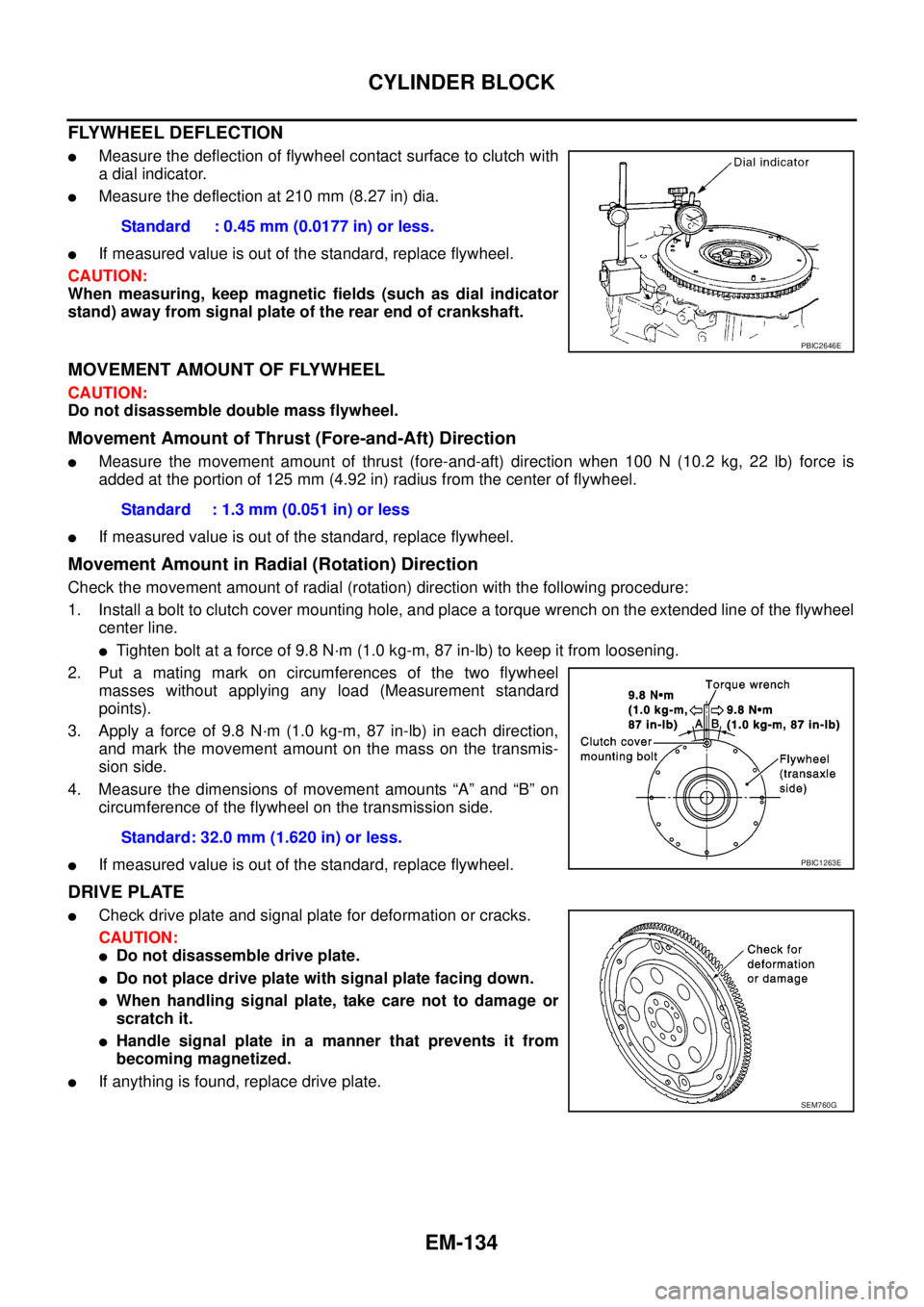
lMeasure the deflection of flywheel contact surface to clutch with
a dial indicator.
lMeasure the deflection at 210 mm (8.27 in) dia.
lIf measured value is out of the standard, replace flywheel.
CAUTION:
When measuring, keep magnetic fields (such as dial indicator
stand) away from signal plate of the rear end of crankshaft.
MOVEMENT AMOUNT OF FLYWHEEL
CAUTION:
Do not disassemble double mass flywheel.
Movement Amount of Thrust (Fore-and-Aft) Direction
lMeasure the movement amount of thrust (fore-and-aft) direction when 100 N (10.2 kg, 22 lb) force is
added at the portion of 125 mm (4.92 in) radius from the center of flywheel.
lIf measured value is out of the standard, replace flywheel.
Movement Amount in Radial (Rotation) Direction
Check the movement amount of radial (rotation) direction with the following procedure:
1. Install a bolt to clutch cover mounting hole, and place a torque wrench on the extended line of the flywheel
center line.
lTighten bolt at a force of 9.8 N·m (1.0 kg-m, 87 in-lb) to keep it from loosening.
2. Put a mating mark on circumferences of the two flywheel
masses without applying any load (Measurement standard
points).
3. Apply a force of 9.8 N·m (1.0 kg-m, 87 in-lb) in each direction,
and mark the movement amount on the mass on the transmis-
sion side.
4. Measure the dimensions of movement amounts “A” and “B” on
circumference of the flywheel on the transmission side.
lIf measured value is out of the standard, replace flywheel.
DRIVE PLATE
lCheck drive plate and signal plate for deformation or cracks.
CAUTION:
lDo not disassemble drive plate.
lDo not place drive plate with signal plate facing down.
lWhen handling signal plate, take care not to damage or
scratch it.
lHandle signal plate in a manner that prevents it from
becoming magnetized.
lIf anything is found, replace drive plate.Standard : 0.45 mm (0.0177 in) or less.
PBIC2646E
Standard : 1.3 mm (0.051 in) or less
Standard: 32.0 mm (1.620 in) or less.
PBIC1263E
SEM760G
Page 1595 of 3171
FUEL TANK
FL-11
C
D
E
F
G
H
I
J
K
L
MA
FL
CAUTION:
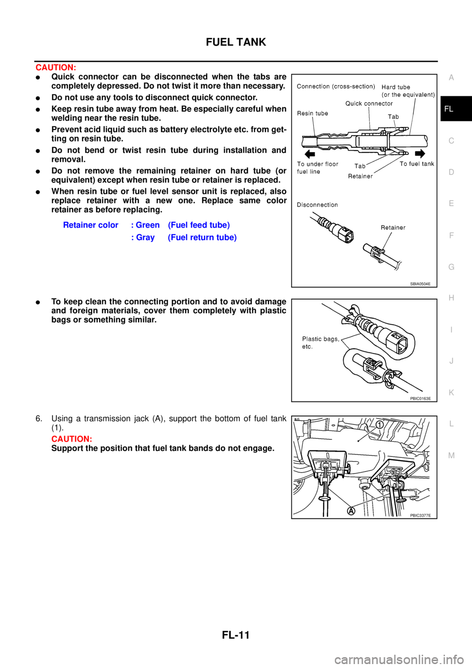
lQuick connector can be disconnected when the tabs are
completely depressed. Do not twist it more than necessary.
lDo not use any tools to disconnect quick connector.
lKeep resin tube away from heat. Be especially careful when
welding near the resin tube.
lPrevent acid liquid such as battery electrolyte etc. from get-
ting on resin tube.
lDo not bend or twist resin tube during installation and
removal.
lDo not remove the remaining retainer on hard tube (or
equivalent) except when resin tube or retainer is replaced.
lWhen resin tube or fuel level sensor unit is replaced, also
replace retainer with a new one. Replace same color
retainer as before replacing.
lTo keep clean the connecting portion and to avoid damage
and foreign materials, cover them completely with plastic
bags or something similar.
6. Using a transmission jack (A), support the bottom of fuel tank
(1).
CAUTION:
Support the position that fuel tank bands do not engage.Retainer color : Green (Fuel feed tube)
: Gray (Fuel return tube)
SBIA0504E
PBIC0163E
PBIC3377E
Page 1596 of 3171
FL-12
FUEL TANK
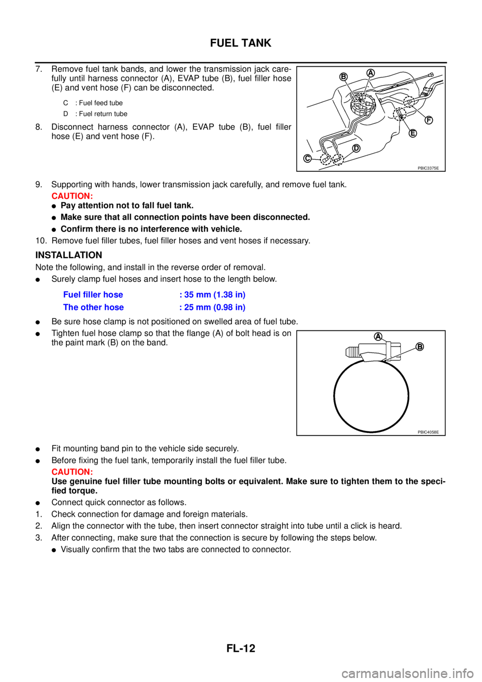
7. Remove fuel tank bands, and lower the transmission jack care-
fully until harness connector (A), EVAP tube (B), fuel filler hose
(E) and vent hose (F) can be disconnected.
8. Disconnect harness connector (A), EVAP tube (B), fuel filler
hose (E) and vent hose (F).
9. Supporting with hands, lower transmission jack carefully, and remove fuel tank.
CAUTION:
lPay attention not to fall fuel tank.
lMake sure that all connection points have been disconnected.
lConfirm there is no interference with vehicle.
10. Remove fuel filler tubes, fuel filler hoses and vent hoses if necessary.
INSTALLATION
Note the following, and install in the reverse order of removal.
lSurely clamp fuel hoses and insert hose to the length below.
lBe sure hose clamp is not positioned on swelled area of fuel tube.
lTighten fuel hose clamp so that the flange (A) of bolt head is on
the paint mark (B) on the band.
lFit mounting band pin to the vehicle side securely.
lBefore fixing the fuel tank, temporarily install the fuel filler tube.
CAUTION:
Use genuine fuel filler tube mounting bolts or equivalent. Make sure to tighten them to the speci-
fied torque.
lConnect quick connector as follows.
1. Check connection for damage and foreign materials.
2. Align the connector with the tube, then insert connector straight into tube until a click is heard.
3. After connecting, make sure that the connection is secure by following the steps below.
lVisually confirm that the two tabs are connected to connector.
C : Fuel feed tube
D : Fuel return tube
PBIC3375E
Fuel filler hose : 35 mm (1.38 in)
The other hose : 25 mm (0.98 in)
PBIC4058E
Page 1624 of 3171

GI-2
TIGHTENING TORQUE OF STANDARD BOLTS .... 55
Tightening Torque Table ......................................... 55
IDENTIFICATION INFORMATION ............................ 56
Model Variation ....................................................... 56
Identification Number .............................................. 57
VEHICLE IDENTIFICATION NUMBER
ARRANGEMENT ................................................. 57
IDENTIFICATION PLATE .................................... 58
ENGINE SERIAL NUMBER ................................ 58TRANSFER SERIAL NUMBER ........................... 58
AUTOMATIC TRANSMISSION NUMBER ........... 58
MANUAL TRANSMISSION NUMBER ................. 59
Dimensions ............................................................. 60
KING CAB ............................................................ 60
DOUBLE CAB ...................................................... 60
Wheels & Tyres ....................................................... 60
TERMINOLOGY ........................................................ 61
ISO 15031-2 Terminology List ................................. 61
Page 1626 of 3171
GI-4
PRECAUTIONS
For this reason, if the battery is disconnected or if the battery is discharged, the steering wheel will lock and
steering wheel rotation will become impossible.
If steering wheel rotation is required when battery power is interrupted, follow the procedure below before
starting the repair operation.
OPERATION PROCEDURE
1. Connect both battery cables.
NOTE:
Supply power using jumper cables if battery is discharged.
2. Use the Intelligent Key or mechanical key to turn the ignition switch to the²ACC²position. At this time, the
steering lock will be released.
3. Disconnect both battery cables. The steering lock will remain released and the steering wheel can be
rotated.
4. Perform the necessary repair operation.
5. When the repair work is completed, return the ignition switch to the²LOCK²position before connecting
the battery cables. (At this time, the steering lock mechanism will engage.)
6. Perform a self-diagnosis check of all control units using CONSULT-II.
General PrecautionsEAS001GJ
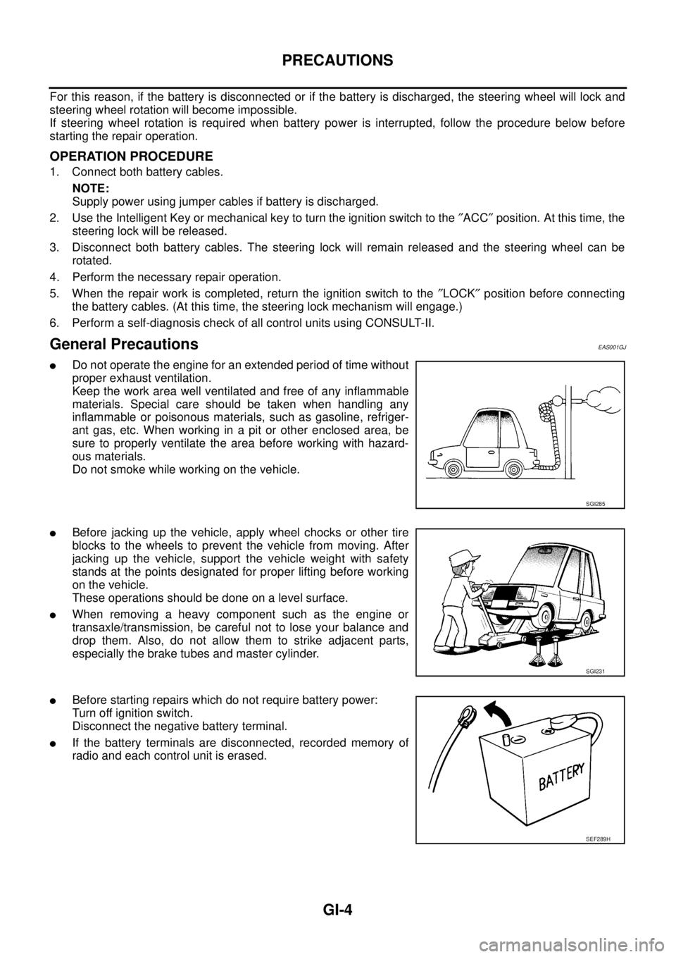
lDo not operate the engine for an extended period of time without
proper exhaust ventilation.
Keep the work area well ventilated and free of any inflammable
materials. Special care should be taken when handling any
inflammable or poisonous materials, such as gasoline, refriger-
ant gas, etc. When working in a pit or other enclosed area, be
sure to properly ventilate the area before working with hazard-
ous materials.
Do not smoke while working on the vehicle.
lBefore jacking up the vehicle, apply wheel chocks or other tire
blocks to the wheels to prevent the vehicle from moving. After
jacking up the vehicle, support the vehicle weight with safety
stands at the points designated for proper lifting before working
on the vehicle.
These operations should be done on a level surface.
lWhen removing a heavy component such as the engine or
transaxle/transmission, be careful not to lose your balance and
drop them. Also, do not allow them to strike adjacent parts,
especially the brake tubes and master cylinder.
lBefore starting repairs which do not require battery power:
Turn off ignition switch.
Disconnect the negative battery terminal.
lIf the battery terminals are disconnected, recorded memory of
radio and each control unit is erased.
SGI285
SGI231
SEF289H
Page 1627 of 3171
PRECAUTIONS
GI-5
C
D
E
F
G
H
I
J
K
L
MB
GI
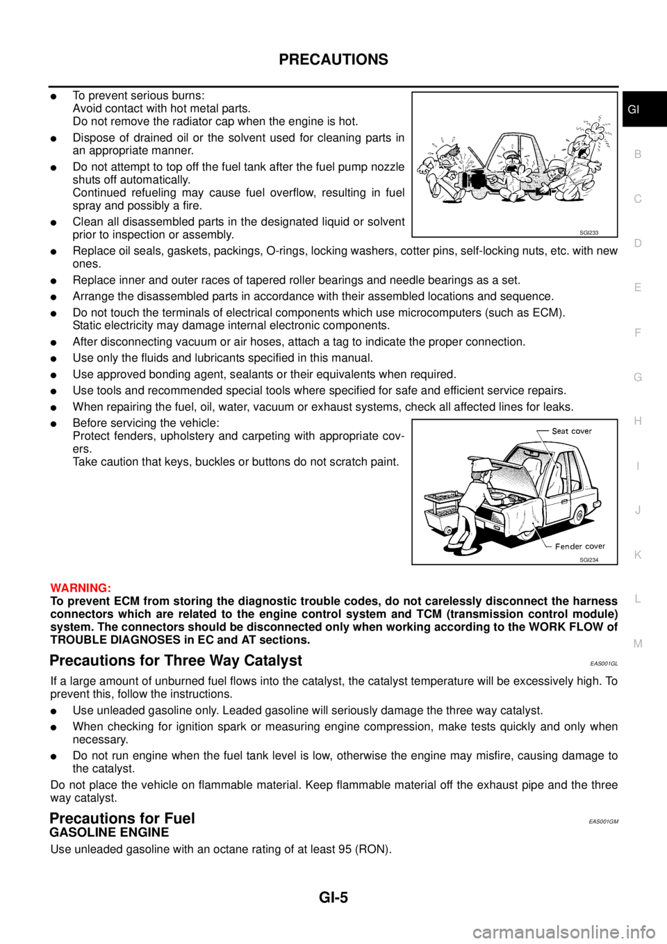
lTo prevent serious burns:
Avoid contact with hot metal parts.
Do not remove the radiator cap when the engine is hot.
lDispose of drained oil or the solvent used for cleaning parts in
an appropriate manner.
lDo not attempt to top off the fuel tank after the fuel pump nozzle
shuts off automatically.
Continued refueling may cause fuel overflow, resulting in fuel
spray and possibly a fire.
lClean all disassembled parts in the designated liquid or solvent
prior to inspection or assembly.
lReplace oil seals, gaskets, packings, O-rings, locking washers, cotter pins, self-locking nuts, etc. with new
ones.
lReplace inner and outer races of tapered roller bearings and needle bearings as a set.
lArrange the disassembled parts in accordance with their assembled locations and sequence.
lDo not touch the terminals of electrical components which use microcomputers (such as ECM).
Static electricity may damage internal electronic components.
lAfter disconnecting vacuum or air hoses, attach a tag to indicate the proper connection.
lUse only the fluids and lubricants specified in this manual.
lUse approved bonding agent, sealants or their equivalents when required.
lUse tools and recommended special tools where specified for safe and efficient service repairs.
lWhen repairing the fuel, oil, water, vacuum or exhaust systems, check all affected lines for leaks.
lBefore servicing the vehicle:
Protect fenders, upholstery and carpeting with appropriate cov-
ers.
Take caution that keys, buckles or buttons do not scratch paint.
WARNING:
To prevent ECM from storing the diagnostic trouble codes, do not carelessly disconnect the harness
connectors which are related to the engine control system and TCM (transmission control module)
system. The connectors should be disconnected only when working according to the WORK FLOW of
TROUBLE DIAGNOSES in EC and AT sections.
Precautions for Three Way CatalystEAS001GL
If a large amount of unburned fuel flows into the catalyst, the catalyst temperature will be excessively high. To
prevent this, follow the instructions.
lUse unleaded gasoline only. Leaded gasoline will seriously damage the three way catalyst.
lWhen checking for ignition spark or measuring engine compression, make tests quickly and only when
necessary.
lDo not run engine when the fuel tank level is low, otherwise the engine may misfire, causing damage to
the catalyst.
Do not place the vehicle on flammable material. Keep flammable material off the exhaust pipe and the three
way catalyst.
Precautions for FuelEAS001GM
GASOLINE ENGINE
Use unleaded gasoline with an octane rating of at least 95 (RON).
SGI233
SGI234
Page 1631 of 3171
HOW TO USE THIS MANUAL
GI-9
C
D
E
F
G
H
I
J
K
L
MB
GI
HOW TO USE THIS MANUALPFP:00008
DescriptionEAS001GS
This volume explains “Removal, Disassembly, Installation, Inspection and Adjustment” and “Trouble Diag-
noses”.
TermsEAS001GT
lThe captionsWARNINGandCAUTIONwarn you of steps that must be followed to prevent personal
injury and/or damage to some part of the vehicle.
WARNINGindicates the possibility of personal injury if instructions are not followed.
CAUTIONindicates the possibility of component damage if instructions are not followed.
BOLD TYPED STATEMENTSexceptWARNINGandCAUTIONgive you helpful information.
Standard value:Tolerance at inspection and adjustment.
Limit value:The maximum or minimum limit value that should not be exceeded at inspection and adjust-
ment.
UnitsEAS001GU
lTheUNITSgiven in this manual are primarily expressed as the SI UNIT (International System of Unit),
and alternatively expressed in the metric system and in the yard/pound system.
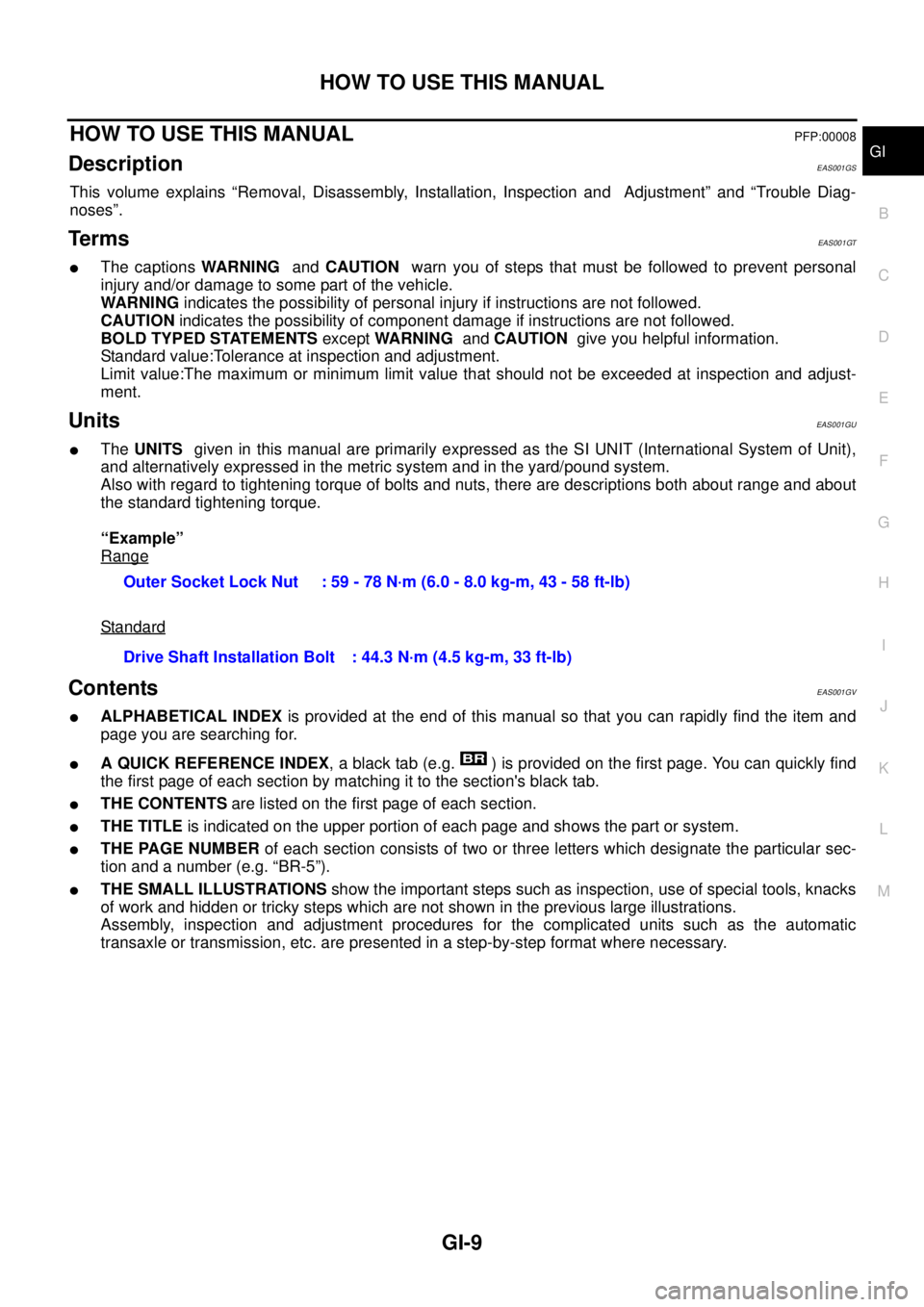
Also with regard to tightening torque of bolts and nuts, there are descriptions both about range and about
the standard tightening torque.
“Example”
Range
Standard
ContentsEAS001GV
lALPHABETICAL INDEXis provided at the end of this manual so that you can rapidly find the item and
page you are searching for.
lA QUICK REFERENCE INDEX, a black tab (e.g. ) is provided on the first page. You can quickly find
the first page of each section by matching it to the section's black tab.
lTHE CONTENTSare listed on the first page of each section.
lTHE TITLEis indicated on the upper portion of each page and shows the part or system.
lTHE PAGE NUMBERof each section consists of two or three letters which designate the particular sec-
tion and a number (e.g. “BR-5”).
lTHE SMALL ILLUSTRATIONSshow the important steps such as inspection, use of special tools, knacks
of work and hidden or tricky steps which are not shown in the previous large illustrations.
Assembly, inspection and adjustment procedures for the complicated units such as the automatic
transaxle or transmission, etc. are presented in a step-by-step format where necessary.Outer Socket Lock Nut : 59 - 78 N·m (6.0 - 8.0 kg-m, 43 - 58 ft-lb)
Drive Shaft Installation Bolt : 44.3 N·m (4.5 kg-m, 33 ft-lb)