2005 NISSAN NAVARA stop start
[x] Cancel search: stop startPage 2129 of 3171

LT-46
HEADLAMP - DAYTIME LIGHT SYSTEM -
4. Select the desired part to be diagnosed on “SELECT DIAG
MODE” screen.
DATA MONITOR
Operation Procedure
1. Touch “DATA MONITOR” on “SELECT DIAG MODE ” screen.
2. Touch “ALL SIGNALS”, “MAIN SIGNALS” or “SELECTION FROM MENU” on “SELECT MONITOR ITEM”
screen.
3. When “SELECTION FROM MENU” is selected, touch individual items to be monitored. In “ALL SIG-
NALS”, all items are monitored. In “MAIN SIGNALS”, predetermined items are monitored.
4. Touch “START”.
5. Touch “RECORD” while monitoring to record the status of the item being monitored. To stop recording,
touch “STOP”.
All Signals, Main Signals, Selection From Menu
NOTE:
Perform monitoring of IPDM E/R data with the ignition switch ON. When the ignition switch is at ACC, the display may not be correct.
ACTIVE TEST
Operation Procedure
1. Touch “ACTIVE TEST” on “SELECT DIAG MODE” screen.
2. Touch “EXTERNAL LAMPS” on “SELECT TEST ITEM” screen.
3. Touch item to be tested, and check operation.
4. Touch “START”.
5. Touch “OFF” while testing to stop the operation.
BCIA0031E
ALL SIGNALS Monitors all items.
MAIN SIGNALS Monitor the predetermined item.
SELECTION FROM MENU Selects items and monitors them.
Item nameCONSULT-II
screen displayDisplayMonitor item selection
Description
ALL
SIGNALSMAIN
SIGNALSSELECTION
FROM MENU
Position lights requestTA I L & C L R
REQON/OFF´´ ´Signal status input from BCM
Headlamp low beam request HL LO REQ ON/OFF´´ ´Signal status input from BCM
Headlamp high beam request HL HI REQ ON/OFF´´ ´Signal status input from BCM
Front fog lights request FR FOG REQ ON/OFF´´ ´Signal status input from BCM
Daytime light request DTRL REQ ON/OFF´´ ´Signal status input from BCM
Page 2130 of 3171

HEADLAMP - DAYTIME LIGHT SYSTEM -
LT-47
C
D
E
F
G
H
I
J
L
MA
B
LT
Daytime Light Control Does Not Operate Properly (Normal Headlamps Operate
Properly)
EKS00Q7Q
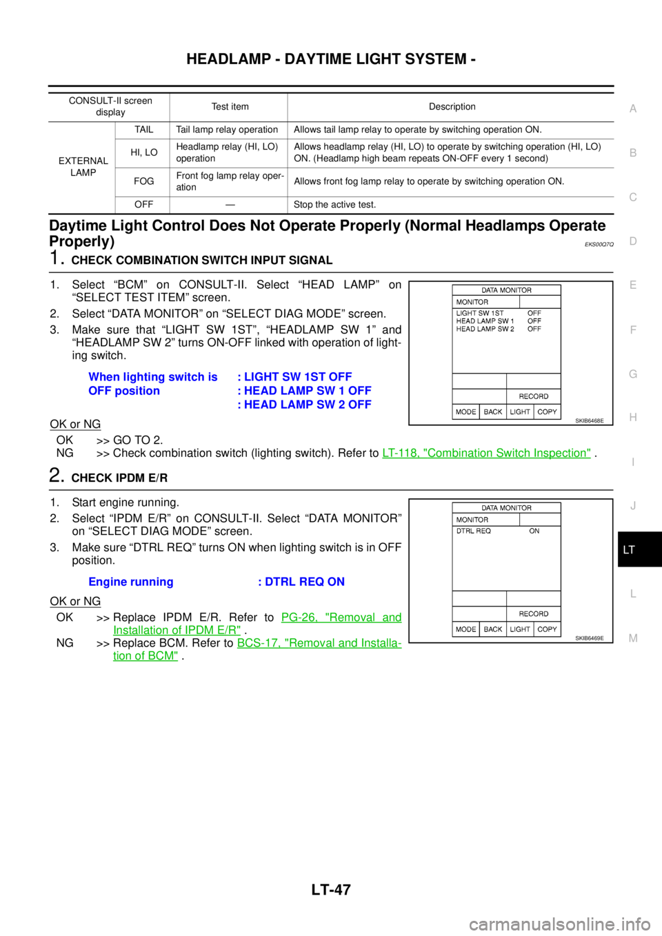
1.CHECK COMBINATION SWITCH INPUT SIGNAL
1. Select “BCM” on CONSULT-II. Select “HEAD LAMP” on
“SELECT TEST ITEM” screen.
2. Select “DATA MONITOR” on “SELECT DIAG MODE” screen.
3. Make sure that “LIGHT SW 1ST”, “HEADLAMP SW 1” and
“HEADLAMP SW 2” turns ON-OFF linked with operation of light-
ing switch.
OK or NG
OK >> GO TO 2.
NG >> Check combination switch (lighting switch). Refer toLT- 11 8 , "
Combination Switch Inspection".
2.CHECK IPDM E/R
1. Start engine running.
2. Select “IPDM E/R” on CONSULT-II. Select “DATA MONITOR”
on “SELECT DIAG MODE” screen.
3. Make sure “DTRL REQ” turns ON when lighting switch is in OFF
position.
OK or NG
OK >> Replace IPDM E/R. Refer toPG-26, "Removal and
Installation of IPDM E/R".
NG >> Replace BCM. Refer toBCS-17, "
Removal and Installa-
tion of BCM".
CONSULT-II screen
displayTest item Description
EXTERNAL
LAMPTAIL Tail lamp relay operation Allows tail lamp relay to operate by switching operation ON.
HI, LOHeadlamp relay (HI, LO)
operationAllows headlamp relay (HI, LO) to operate by switching operation (HI, LO)
ON. (Headlamp high beam repeats ON-OFF every 1 second)
FOGFront fog lamp relay oper-
ationAllows front fog lamp relay to operate by switching operation ON.
OFF — Stoptheactivetest.
When lighting switch is
OFF position:LIGHTSW1STOFF
: HEAD LAMP SW 1 OFF
: HEAD LAMP SW 2 OFF
SKIB6468E
Engine running : DTRL REQ ON
SKIB6469E
Page 2143 of 3171

LT-60
AUTO LIGHT SYSTEM
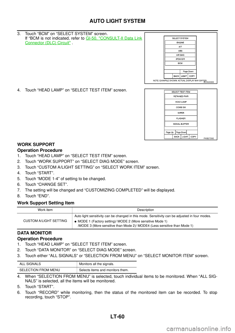
3. Touch “BCM” on “SELECT SYSTEM” screen.
If “BCM is not indicated, refer toGI-50, "
CONSULT-II Data Link
Connector (DLC) Circuit".
4. Touch “HEAD LAMP” on “SELECT TEST ITEM” screen.
WORK SUPPORT
Operation Procedure
1. Touch “HEAD LAMP” on “SELECT TEST ITEM” screen.
2. Touch “WORK SUPPORT” on “SELECT DIAG MODE” screen.
3. Touch “CUSTOM A/LIGHT SETTING” on “SELECT WORK ITEM” screen.
4. Touch “START”.
5. Touch “MODE 1-4” of setting to be changed.
6. Touch “CHANGE SET”.
7. The setting will be changed and “CUSTOMIZING COMPLETED” will be displayed.
8. Touch “END”.
Work Support Setting Item
DATA MONITOR
Operation Procedure
1. Touch “HEAD LAMP” on “SELECT TEST ITEM” screen.
2. Touch “DATA MONITOR” on “SELECT DIAG MODE” screen.
3. Touch either “ALL SIGNALS” or “SELECTION FROM MENU” on “SELECT MONITOR ITEM” screen.
4. When “SELECTION FROM MENU” is selected, touch individual items to be monitored. When “ALL SIG-
NALS” is selected, all the items will be monitored.
5. Touch “START”.
6. Touch “RECORD” while monitoring, then the status of the monitored item can be recorded. To stop
recording, touch “STOP”.
BCIA0030E
PKIB2726E
Work item Description
CUSTOM A/LIGHT SETTINGAuto light sensitivity can be changed in this mode. Sensitivity can be adjusted in four modes.
lMODE 1 (Factory setting)/ MODE 2 (More sensitive Mode 1)
/MODE 3 (More sensitive than Mode 2)/ MODE4 (Less sensitive than Mode 1)
ALL SIGNALS Monitors all the signals.
SELECTION FROM MENU Selects items and monitors them.
Page 2189 of 3171

LT-106
TURN SIGNAL AND HAZARD WARNING LAMPS
4. Touch “FLASHER” on “SELECT TEST ITEM” screen.
DATA MONITOR
Operation Procedure
1. Touch “FLASHER” on “SELECT TEST ITEM” screen.
2. Touch “DATA MONITOR” on “SELECT DIAG MODE” screen.
3. Touch either “ALL SIGNALS” or “SELECTION FROM MENU” on “SELECT MONITOR ITEM” screen.
4. When “SELECTION FROM MENU” is selected, touch items to be monitored. When “ALL SIGNALS” is
selected, all the items will be monitored.
5. Touch “START”.
6. Touch “RECORD” while monitoring, then the status of the monitored item can be recorded. To stop
recording, touch “STOP”.
Display Item List
ACTIVE TEST
Operation Procedure
1. Touch “FLASHER” on “SELECT TEST ITEM” screen.
2. Touch “ACTIVE TEST” on “SELECT DIAG MODE” screen.
3. Touch item to be tested and check operation of the selected item.
4. During the operation check, touching “OFF” deactivates the operation.
Display Item List
PKIC0325E
ALL SIGNALS Monitors all the signals.
SELECTION FROM MENU Selects items and monitors them.
Monitor item Contents
IGN ON SW “ON/OFF”Displays status (ignition switch IGN position: ON/other: OFF) of ignition switch judged from the
ignition switch signal.
HAZARD SW “ON/OFF”Displays status (hazard switch ON position: ON/other: OFF) of hazard switch judged from the
hazard switch signal.
TURN SIGNAL R “ON/OFF”Displays status (turn signal switch right position: ON/other: OFF) of turn RH switch judged from
the turn signal switch signal.
TURN SIGNAL L “ON/OFF”Displays status (turn signal switch left position: ON/other: OFF) of turn LH switch judged from
the turn signal switch signal.
BRAKE SW “ON/OFF” Displays status of stop lamp switch.
Test item Description
FLASHER (RH) Turn signal lamp (right) can be operated by any ON-OFF operations.
FLASHER (LH) Turn signal lamp (left) can be operated by any ON-OFF operations.
Page 2199 of 3171

LT-116
COMBINATION SWITCH
4. Touch “COMB SW” on “SELECT TEST ITEM” screen.
DATA MONITOR
Operation Procedure
1. Touch “COMB SW” on “SELECT TEST ITEM” screen.
2. Touch “DATA MONITOR” on “SELECT DIAG MODE” screen.
3. Touch either “ALL SIGNALS” or “SELECTION FROM MENU” on “SELECT MONITOR ITEM” screen.
4. When “ALL SIGNALS” is selected, all the signals will be monitored. When “SELECTION FROM MENU” is
selected, touch items to be monitored.
5. Touch “START”.
6. Touch “RECORD” while monitoring, then the status of the monitored item can be recorded. To stop
recording, touch “STOP”.
Display Item List
PKIB6096E
ALL SIGNALS Monitors all the signals.
SELECTION FROM MENU Selects and monitors individual signal.
Monitor item Contents
TURN SIGNAL R “ON/OFF”Displays status (turn signal switch right position: ON/other: OFF) of turn RH switch judged from the
turn signal switch signal.
TURN SIGNAL L “ON/OFF”Displays status (turn signal switch left position: ON/other: OFF) of turn LH switch judged from the
turn signal switch signal.
HI BEAM SW “ON/OFF”Displays status (lighting switch high beam position: ON/other: OFF) of high beam switch judged
from the lighting switch signal.
HEAD LAMP SW 1 “ON/OFF”Displays status (lighting switch 2ND position: ON/other: OFF) of headlamp 1 switch judged from
the lighting switch signal.
HEAD LAMP SW 2 “ON/OFF”Displays status (lighting switch 2ND position: ON/other: OFF) of headlamp 2 switch judged from
the lighting switch signal.
LIGHT SW 1ST “ON/OFF”Displays status (lighting switch 1ST or 2ND position: ON/other: OFF) of lighting switch 1ST position
switch judged from the lighting switch signal.
PASSING SW “ON/OFF”Displays status (lighting switch passing position: ON/other: OFF) of passing switch judged from the
lighting switch signal.
FR FOG SW “ON/OFF”Displays status (lighting switch front fog lamp ON position: ON/others: OFF) of front fog lamp
switch judged from the lighting switch signal.
RR FOG SW “ON/OFF”Displays status (rear fog lamp switch position: ON/other: OFF) of rear fog switch judged from the
lighting switch signal.
FR WIPER HI “ON/OFF”Displays status (front wiper switch high position: ON/other: OFF) of front wiper high switch judged
from the wiper switch signal.
FR WIPER LOW “ON/OFF”Displays status (front wiper switch low position: ON/other: OFF) of front wiper low switch judged
from the wiper switch signal.
FR WIPER INT “ON/OFF”Displays status (front wiper switch intermittent position: ON/other: OFF) of front wiper intermittent
switch judged from the wiper switch signal.
FR WASHER SW “ON/OFF”Displays status (front washer switch ON position: ON/other: OFF) of front washer switch judged
from the wiper switch signal.
Page 2241 of 3171

LT-158
INTERIOR ROOM LAMP
4. Touch “INT LAMP” on “SELECT SYSTEM” screen.
WORK SUPPORT
Operation Procedure
1. Touch “INT LAMP” on “SELECT SYSTEM” screen.
2. Touch “WORK SUPPORT” on “SELECT DIAG MODE” screen.
3. Touch “SET I/L D-UNLCK INTCON” on “SELECT WORK ITEM” screen.
4. Touch “START”.
5. Touch “CHANGE SETT”.
6. The setting will be changed and “CUSTOMIZING COMPLETED” will be displayed.
7. Touch “END”.
Display Item List
Reference between “MODE” and “TIME” for “TURN ON/OFF”.
DATA MONITOR
Operation Procedure
1. Touch “INT LAMP” on “SELECT TEST ITEM” screen.
2. Touch “DATA MONITOR” on “SELECT DIAG MODE” screen.
3. Touch either “ALL SIGNALS” or “SELECTION FROM MENU” on “SELECT MONITOR ITEM” screen.
4. When “ALL SIGNALS” is selected, all the items will be monitored. When “SELECTION FROM MENU” is
selected, touch items to be monitored.
5. Touch “START”.
6. Touch “RECORD” while monitoring, then the status of the monitored item can be recorded. To stop
recording, touch “STOP”.
PKIC0325E
Item Description CONSULT-II
SET I/L D-UNLCK INTCONThe 30 seconds operating function of the interior room lamps and the ignition key-
hole illumination can be selected when driver's door is released (unlocked).ON/OFF
ROOM LAMP ON TIME SETThe time in order to escalate illumination can be selected when the interior room
lamps and the ignition keyhole illumination is turned on.MODE 1 - 7
ROOM LAMP OFF TIME SETThe time in order to diminish illumination can be selected when the interior room
lamps and the ignition keyhole illumination is turned off.MODE 1 - 7
MODE 1 2 3 4 5 6 7
Time (sec.) 0.5 1 2 3 4 5 0
ALL SIGNALS Monitors all the signals.
SELECTION FROM MENU Selects and monitors the individual signal.
Page 2262 of 3171

ENGINE OIL
LU-5
C
D
E
F
G
H
I
J
K
L
MA
LU
ENGINE OILPFP:KLA92
InspectionEBS01E56
ENGINE OIL LEVEL
NOTE:
Before starting engine, put vehicle horizontally and check the engine oil level. If engine is already started, stop
it and allow 10 minutes before checking.
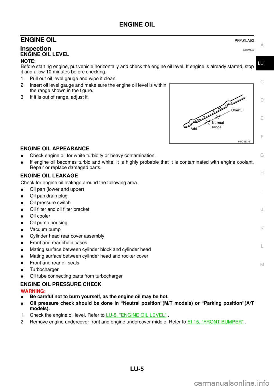
1. Pull out oil level gauge and wipe it clean.
2. Insert oil level gauge and make sure the engine oil level is within
the range shown in the figure.
3. If it is out of range, adjust it.
ENGINE OIL APPEARANCE
lCheck engine oil for white turbidity or heavy contamination.
lIf engine oil becomes turbid and white, it is highly probable that it is contaminated with engine coolant.
Repair or replace damaged parts.
ENGINE OIL LEAKAGE
Check for engine oil leakage around the following area.
lOil pan (lower and upper)
lOil pan drain plug
lOil pressure switch
lOil filter and oil filter bracket
lOil cooler
lOil pump housing
lVa c u u m p u m p
lCylinder head rear cover assembly
lFront and rear chain cases
lMating surface between cylinder block and cylinder head
lMating surface between cylinder head and rocker cover
lFront and rear oil seals
lTurbocharger
lOil tube connecting parts from turbocharger
ENGINE OIL PRESSURE CHECK
WARNING:
lBe careful not to burn yourself, as the engine oil may be hot.
lOil pressure check should be done in “Neutral position”(M/T models) or “Parking position”(A/T
models).
1. Check the engine oil level. Refer toLU-5, "
ENGINE OIL LEVEL".
2. Remove engine undercover front and engine undercover middle. Refer toEI-15, "
FRONT BUMPER".
PBIC2823E
Page 2263 of 3171

LU-6
ENGINE OIL
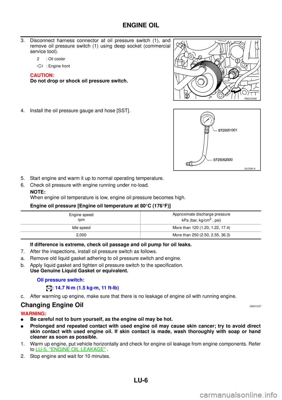
3. Disconnect harness connector at oil pressure switch (1), and
remove oil pressure switch (1) using deep socket (commercial
service tool).
CAUTION:
Do not drop or shock oil pressure switch.
4. Install the oil pressure gauge and hose [SST].
5. Start engine and warm it up to normal operating temperature.
6. Check oil pressure with engine running under no-load.
NOTE:
When engine oil temperature is low, engine oil pressure becomes high.
Engine oil pressure [Engine oil temperature at 80°C(176°F)]
If difference is extreme, check oil passage and oil pump for oil leaks.
7. After the inspections, install oil pressure switch as follows.
a. Remove old liquid gasket adhering to oil pressure switch and engine.
b. Apply liquid gasket and tighten oil pressure switch to the specification.
Use Genuine Liquid Gasket or equivalent.
c. After warming up engine, make sure that there is no leakage of engine oil with running engine.
Changing Engine OilEBS01E57
WARNING:
lBe careful not to burn yourself, as the engine oil may be hot.
lProlonged and repeated contact with used engine oil may cause skin cancer; try to avoid direct
skin contact with used engine oil. If skin contact is made, wash thoroughly with soap or hand
cleaner as soon as possible.
1. Warm up engine, put vehicle horizontally and check for engine oil leakage from engine components. Refer
toLU-5, "
ENGINE OIL LEAKAGE".
2. Stop engine and wait for 10 minutes.
2 : Oil cooler
: Engine front
PBIC3334E
SLC926-A
Engine speed
rpmApproximate discharge pressure
kPa (bar, kg/cm2, psi)
Idle speed More than 120 (1.20, 1.22, 17.4)
2,000 More than 250 (2.50, 2.55, 36.3)
Oil pressure switch:
: 14.7 N·m (1.5 kg-m, 11 ft-lb)