2005 NISSAN NAVARA stop start
[x] Cancel search: stop startPage 2766 of 3171
![NISSAN NAVARA 2005 Repair Workshop Manual TROUBLE DIAGNOSIS FOR SYSTEM
RFD-63
[WITH ELECTRONIC LOCKING DIFFERENTIAL]
C
E
F
G
H
I
J
K
L
MA
B
RFD
COMPONENT INSPECTION
1. Turn ignition switch “OFF”.
2. Disconnect differential lock position s NISSAN NAVARA 2005 Repair Workshop Manual TROUBLE DIAGNOSIS FOR SYSTEM
RFD-63
[WITH ELECTRONIC LOCKING DIFFERENTIAL]
C
E
F
G
H
I
J
K
L
MA
B
RFD
COMPONENT INSPECTION
1. Turn ignition switch “OFF”.
2. Disconnect differential lock position s](/manual-img/5/57362/w960_57362-2765.png)
TROUBLE DIAGNOSIS FOR SYSTEM
RFD-63
[WITH ELECTRONIC LOCKING DIFFERENTIAL]
C
E
F
G
H
I
J
K
L
MA
B
RFD
COMPONENT INSPECTION
1. Turn ignition switch “OFF”.
2. Disconnect differential lock position switch harness connector.
3. Remove differential lock position switch. Refer toRFD-45, "
Location of Electrical Parts".
4. Pull differential lock position switch and check continuity
between differential lock position switch harness connector ter-
minals.
5. If NG, replace differential lock position switch.
Differential Lock Solenoid RelayEDS003B5
CONSULT-II REFERENCE VALUE IN DATA MONITOR MODE
Data are reference value.
DIAGNOSTIC PROCEDURE
1.CHECK DIFFERENTIAL LOCK SOLENOID SYSTEM
Perform self-diagnosis. Refer toRFD-51, "
SELF-DIAG RESULTS MODE".
Is
“RELAY [P1844]”displayed?
YES >> Perform trouble diagnosis for differential lock solenoid. Refer toRFD-64, "Differential Lock Sole-
noid".
NO >> GO TO 2.
2.CHECK DIFFERENTIAL LOCK SOLENOID RELAY SIGNAL
With CONSULT-II
1. Start engine.
2. Select “DATA MONITOR” mode for “DIFF LOCK” with CONSULT-II.
3. Read out ON/OFF switching action of “RELAY ON”.
OK or NG
OK >> GO TO 4.
NG >> GO TO 3.
Terminal Condition Continuity
1-2Pull differential position switch Yes
Release Differential position switch No
SDIA3429E
Monitor item [Unit] Content Condition Display value
RELAY ON [ON/OFF]Operating condition of dif-
ferential lock solenoid
relay (integrated in differ-
ential lock control unit)
lVehicle stopped
lEngine running
l4WD shift switch: 4LODifferential lock mode
switch: ONON
Differential lock mode
switch: OFFOFF
Monitor item ConditionDisplay
value
RELAY ON
lVehicle stopped
lEngine running
l4WD shift
switch: 4LODifferential lock mode
switch: ONON
Differential lock mode
switch: OFFOFF
SDIA2642E
Page 2768 of 3171
![NISSAN NAVARA 2005 Repair Workshop Manual TROUBLE DIAGNOSIS FOR SYSTEM
RFD-65
[WITH ELECTRONIC LOCKING DIFFERENTIAL]
C
E
F
G
H
I
J
K
L
MA
B
RFD
DIAGNOSTIC PROCEDURE
1.CHECK DIFFERENTIAL SOLENOID SIGNAL
With CONSULT-II
1. Start engine.
2. Sele NISSAN NAVARA 2005 Repair Workshop Manual TROUBLE DIAGNOSIS FOR SYSTEM
RFD-65
[WITH ELECTRONIC LOCKING DIFFERENTIAL]
C
E
F
G
H
I
J
K
L
MA
B
RFD
DIAGNOSTIC PROCEDURE
1.CHECK DIFFERENTIAL SOLENOID SIGNAL
With CONSULT-II
1. Start engine.
2. Sele](/manual-img/5/57362/w960_57362-2767.png)
TROUBLE DIAGNOSIS FOR SYSTEM
RFD-65
[WITH ELECTRONIC LOCKING DIFFERENTIAL]
C
E
F
G
H
I
J
K
L
MA
B
RFD
DIAGNOSTIC PROCEDURE
1.CHECK DIFFERENTIAL SOLENOID SIGNAL
With CONSULT-II
1. Start engine.
2. Select “DATA MONITOR” mode for “DIFF LOCK” with CONSULT-II.
3. Read out ON/OFF switching action of “RELAY ON”, “RELAY
MTR”, “SOL MTR”.
Without CONSULT-II
1. Start engine.
2. Check voltage between differential lock control unit harness
connector terminal and ground.
OK or NG
OK >> GO TO 6.
NG >> GO TO 2.
Monitor item ConditionDisplay
value
RELAY ON
lVehicle stopped
lEngine running
l4WD shift
switch: 4LODifferential lock mode
switch: ONON
Differential lock mode
switch: OFFOFF
RELAY MTRDifferential lock mode
switch: ONON
Differential lock mode
switch: OFFOFF
SOL MTRDifferential lock mode
switch: ONON
Differential lock mode
switch: OFFOFF
Connector Terminal ConditionData
(Approx.)
M10711 -
Ground
lVehicle stopped
lEngine running
l4WD shift switch: 4LODifferential
lock mode
switch: ON0V
Differential
lock mode
switch: OFFBattery
voltage
12 -
GroundDifferential
lock mode
switch: ON0V
Differential
lock mode
switch: OFFBattery
voltage
SDIA2539E
SDIA2565E
Page 2844 of 3171
BATTERY
SC-11
C
D
E
F
G
H
I
J
L
MA
B
SC
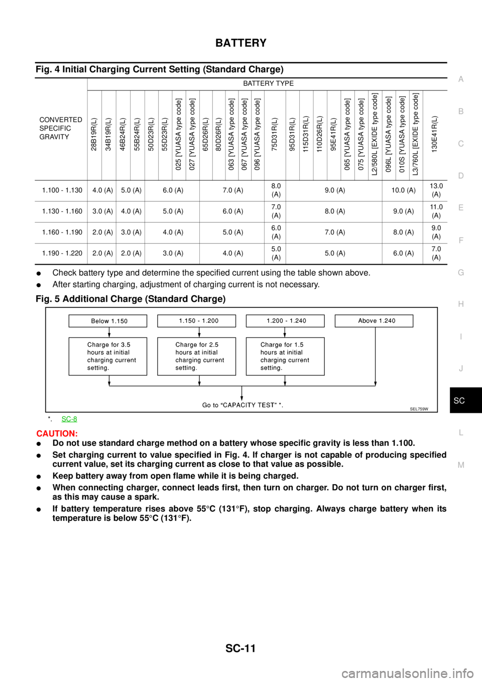
Fig. 4 Initial Charging Current Setting (Standard Charge)
lCheck battery type and determine the specified current using the table shown above.
lAfter starting charging, adjustment of charging current is not necessary.
Fig. 5 Additional Charge (Standard Charge)
CAUTION:
lDo not use standard charge method on a battery whose specific gravity is less than 1.100.
lSet charging current to value specified in Fig. 4. If charger is not capable of producing specified
current value, set its charging current as close to that value as possible.
lKeep battery away from open flame while it is being charged.
lWhen connecting charger, connect leads first, then turn on charger. Do not turn on charger first,
as this may cause a spark.
lIf battery temperature rises above 55°C(131°F), stop charging. Always charge battery when its
temperature is below 55°C(131°F).
CONVERTED
SPECIFIC
GRAVITYBATTERY TYPE
28B19R(L)
34B19R(L)
46B24R(L)
55B24R(L)
50D23R(L)
55D23R(L)
025 [YUASA type code]
027 [YUASA type code]
65D26R(L)
80D26R(L)
063 [YUASA type code]
067 [YUASA type code]
096 [YUASA type code]
75D31R(L)
95D31R(L)
115D31R(L)
110D26R(L)
95E41R(L)
065 [YUASA type code]
075 [YUASA type code]
L2/580L [EXIDE type code]
096L [YUASA type code]
010S [YUASA type code]
L3/760L [EXIDE type code]
130E41R(L)
1.100 - 1.130 4.0 (A) 5.0 (A) 6.0 (A) 7.0 (A)8.0
(A)9.0 (A) 10.0 (A)13.0
(A)
1.130 - 1.160 3.0 (A) 4.0 (A) 5.0 (A) 6.0 (A)7.0
(A)8.0(A) 9.0(A)11 . 0
(A)
1.160 - 1.190 2.0 (A) 3.0 (A) 4.0 (A) 5.0 (A)6.0
(A)7.0(A) 8.0(A)9.0
(A)
1.190 - 1.220 2.0 (A) 2.0 (A) 3.0 (A) 4.0 (A)5.0
(A)5.0(A) 6.0(A)7.0
(A)
*.SC-8
SEL759W
Page 2845 of 3171
SC-12
BATTERY
C: QUICK CHARGE
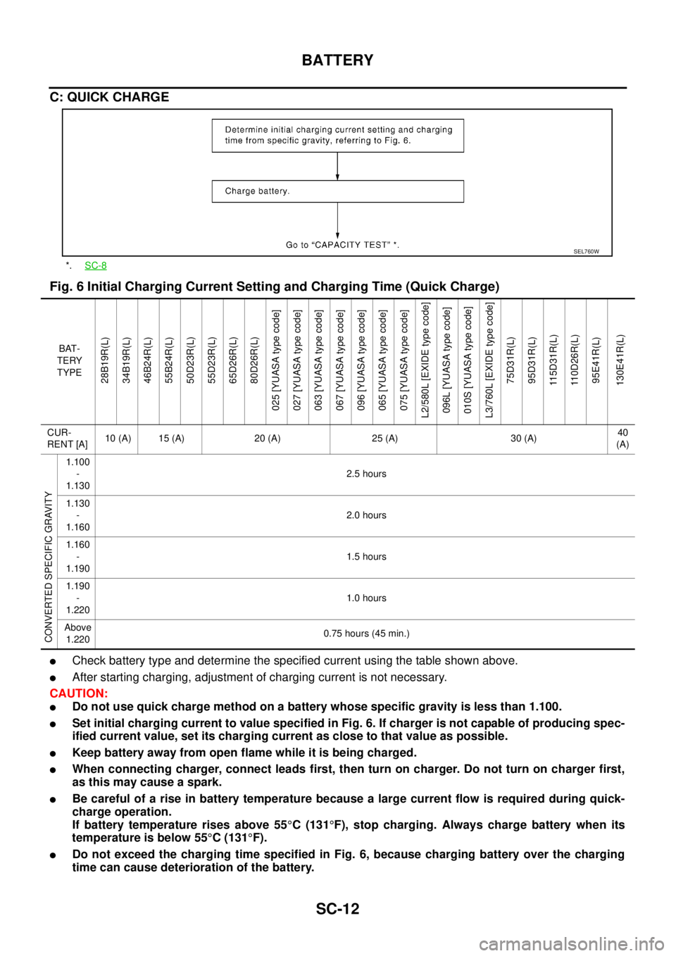
Fig. 6 Initial Charging Current Setting and Charging Time (Quick Charge)
lCheck battery type and determine the specified current using the table shown above.
lAfter starting charging, adjustment of charging current is not necessary.
CAUTION:
lDo not use quick charge method on a battery whose specific gravity is less than 1.100.
lSet initial charging current to value specified in Fig. 6. If charger is not capable of producing spec-
ified current value, set its charging current as close to that value as possible.
lKeep battery away from open flame while it is being charged.
lWhen connecting charger, connect leads first, then turn on charger. Do not turn on charger first,
as this may cause a spark.
lBe careful of a rise in battery temperature because a large current flow is required during quick-
charge operation.
If battery temperature rises above 55°C(131°F), stop charging. Always charge battery when its
temperature is below 55°C(131°F).
lDo not exceed the charging time specified in Fig. 6, because charging battery over the charging
time can cause deterioration of the battery.
*.SC-8
SEL760W
BAT-
TERY
TYPE
28B19R(L)
34B19R(L)
46B24R(L)
55B24R(L)
50D23R(L)
55D23R(L)
65D26R(L)
80D26R(L)
025 [YUASA type code]
027 [YUASA type code]
063 [YUASA type code]
067 [YUASA type code]
096 [YUASA type code]
065 [YUASA type code]
075 [YUASA type code]
L2/580L [EXIDE type code]
096L [YUASA type code]
010S [YUASA type code]
L3/760L [EXIDE type code]
75D31R(L)
95D31R(L)
115D31R(L)
110D26R(L)
95E41R(L)
130E41R(L)
CUR-
RENT [A]10 (A) 15 (A) 20 (A) 25 (A) 30 (A)40
(A)
CONVERTED SPECIFIC GRAVITY
1.100
-
1.1302.5 hours
1.130
-
1.1602.0 hours
1.160
-
1.1901.5 hours
1.190
-
1.2201.0 hours
Above
1.2200.75 hours (45 min.)
Page 2865 of 3171
SC-32
STARTING SYSTEM
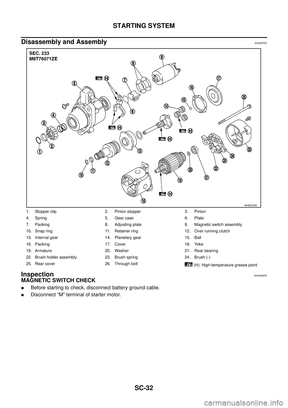
Disassembly and Assembly
EKS00PD2
InspectionEKS00MZR
MAGNETIC SWITCH CHECK
lBefore starting to check, disconnect battery ground cable.
lDisconnect “M” terminal of starter motor.
1. Stopper clip 2. Pinion stopper 3. Pinion
4. Spring 5. Gear case 6. Plate
7. Packing 8. Adjusting plate 9. Magnetic switch assembly
10. Snap ring 11. Retainer ring 12. Over running clutch
13. Internal gear 14. Planetary gear 15. Ball
16. Packing 17. Cover 18. Yoke
19. Armature 20. Washer 21. Rear bearing
22. Brush holder assembly 23. Brush spring 24. Brush (-)
25. Rear cover 26. Through bolt
(H): High-temperature grease point
MKIB2003E
Page 2869 of 3171
SC-36
STARTING SYSTEM
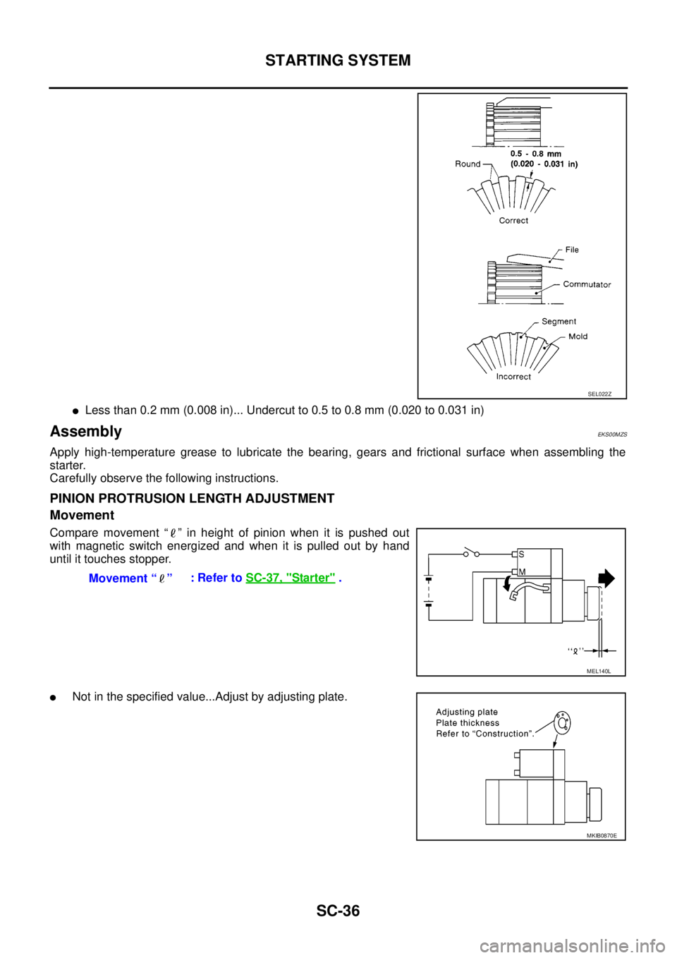
lLess than 0.2 mm (0.008 in)... Undercut to 0.5 to 0.8 mm (0.020 to 0.031 in)
AssemblyEKS00MZS
Apply high-temperature grease to lubricate the bearing, gears and frictional surface when assembling the
starter.
Carefully observe the following instructions.
PINION PROTRUSION LENGTH ADJUSTMENT
Movement
Compare movement “ ” in height of pinion when it is pushed out
with magnetic switch energized and when it is pulled out by hand
until it touches stopper.
lNot in the specified value...Adjust by adjusting plate.
SEL022Z
Movement “ ”:RefertoSC-37, "Starter".
MEL140L
MKIB0870E
Page 2870 of 3171
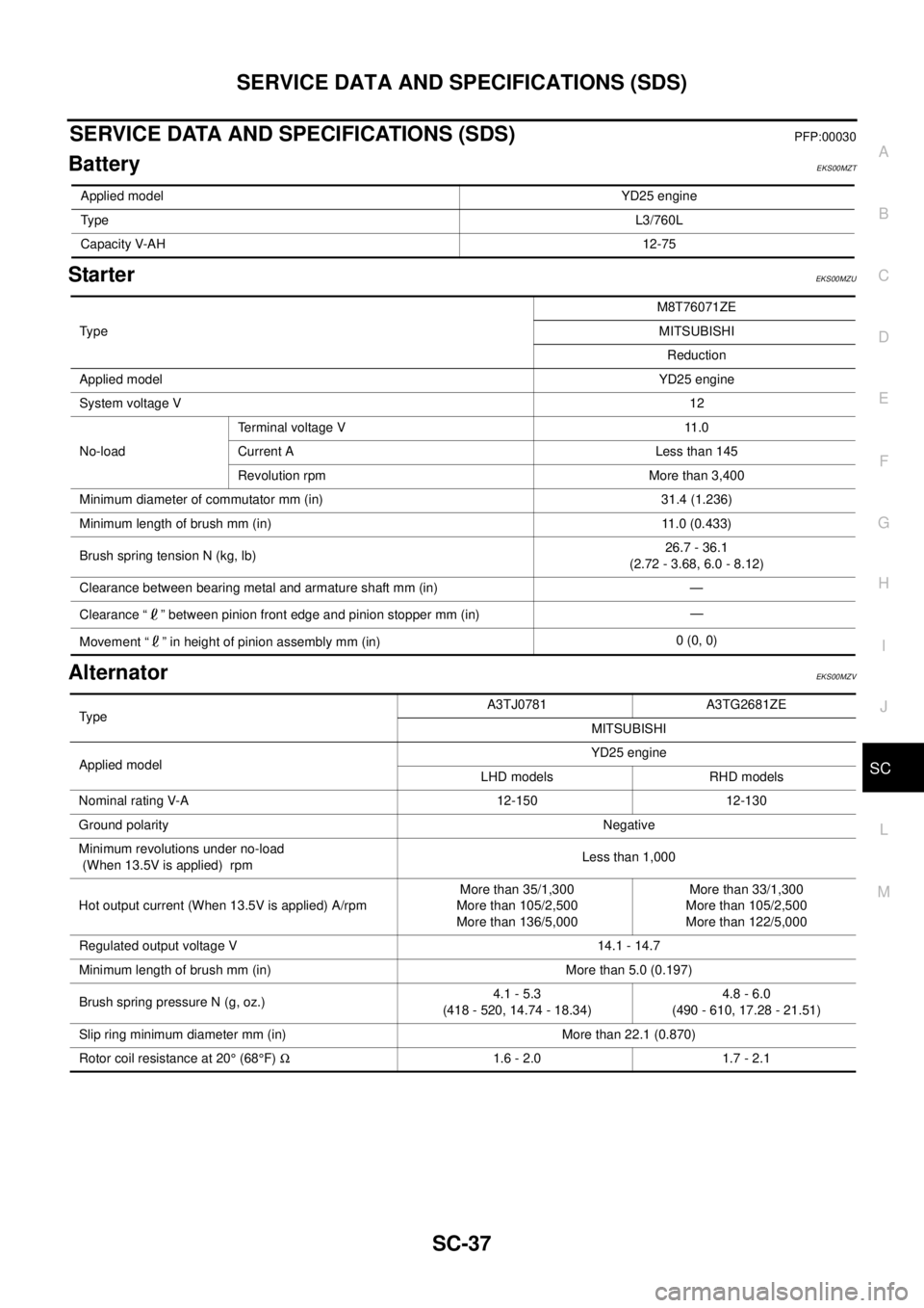
SERVICE DATA AND SPECIFICATIONS (SDS)
SC-37
C
D
E
F
G
H
I
J
L
MA
B
SC
SERVICE DATA AND SPECIFICATIONS (SDS)PFP:00030
BatteryEKS00MZT
StarterEKS00MZU
AlternatorEKS00MZV
Applied modelYD25 engine
TypeL3/760L
Capacity V-AH12-75
Ty p eM8T76071ZE
MITSUBISHI
Reduction
Applied modelYD25 engine
System voltage V12
No-loadTerminal voltage V 11.0
Current A Less than 145
Revolution rpm More than 3,400
Minimum diameter of commutator mm (in) 31.4 (1.236)
Minimum length of brush mm (in) 11.0 (0.433)
Brush spring tension N (kg, lb)26.7 - 36.1
(2.72 - 3.68, 6.0 - 8.12)
Clearance between bearing metal and armature shaft mm (in) —
Clearance “ ” between pinion front edge and pinion stopper mm (in)—
Movement “ ” in height of pinion assembly mm (in)0 (0, 0)
TypeA3TJ0781 A3TG2681ZE
MITSUBISHI
Applied modelYD25 engine
LHD models RHD models
Nominal rating V-A 12-150 12-130
Ground polarityNegative
Minimum revolutions under no-load
(When 13.5V is applied) rpmLess than 1,000
Hot output current (When 13.5V is applied) A/rpmMore than 35/1,300
More than 105/2,500
More than 136/5,000More than 33/1,300
More than 105/2,500
More than 122/5,000
Regulated output voltage V 14.1 - 14.7
Minimum length of brush mm (in) More than 5.0 (0.197)
Brush spring pressure N (g, oz.)4.1 - 5.3
(418 - 520, 14.74 - 18.34)4.8 - 6.0
(490 - 610, 17.28 - 21.51)
Slip ring minimum diameter mm (in) More than 22.1 (0.870)
Rotor coil resistance at 20°(68°F)W1.6 - 2.0 1.7 - 2.1
Page 2877 of 3171

SE-6
SQUEAK AND RATTLE TROUBLE DIAGNOSES
FELT CLOTHTAPE
Used to insulate where movement does not occur. Ideal for instrument panel applications.
68370-4B000: 15´25 mm (0.59´0.98 in) pad/68239-13E00: 5 mm (0.20 in) wide tape roll
The following materials, not available through NISSAN Parts Department, can also be used to repair squeaks
and rattles.
UHMW(TEFLON) TAPE
Insulates where slight movement is present. Ideal for instrument panel applications.
SILICONE GREASE
Used in place of UHMW tape that will be visible or not fit.
Note: Will only last a few months.
SILICONE SPRAY
Use when grease cannot be applied.
DUCT TAPE
Use to eliminate movement.
CONFIRM THE REPAIR
Confirm that the cause of a noise is repaired by test driving the vehicle. Operate the vehicle under the same
conditions as when the noise originally occurred. Refer to the notes on the Diagnostic Worksheet.
Generic Squeak and Rattle TroubleshootingEIS00CEI
Refer to Table of Contents for specific component removal and installation information.
INSTRUMENT PANEL
Most incidents are caused by contact and movement between:
1. Cluster lid A and instrument panel
2. Acrylic lens and combination meter housing
3. Instrument panel to front pillar garnish
4. Instrument panel to windshield
5. Instrument panel mounting pins
6. Wiring harnesses behind the combination meter
7. A/C defroster duct and duct joint
These incidents can usually be located by tapping or moving the components to duplicate the noise or by
pressing on the components while driving to stop the noise. Most of these incidents can be repaired by apply-
ing felt cloth tape or silicon spray (in hard to reach areas). Urethane pads can be used to insulate wiring har-
ness.
CAUTION:
Do not use silicone spray to isolate a squeak or rattle. If you saturate the area with silicone, you will
not be able to recheck the repair.
CENTER CONSOLE
Components to pay attention to include:
1. Shifter assembly cover to finisher
2. A/C control unit and cluster lid C
3. Wiring harnesses behind audio and A/C control unit
The instrument panel repair and isolation procedures also apply to the center console.
DOORS
Pay attention to the:
1. Finisher and inner panel making a slapping noise
2. Inside handle escutcheon to door finisher
3. Wiring harnesses tapping
4. Door striker out of alignment causing a popping noise on starts and stops
Tapping or moving the components or pressing on them while driving to duplicate the conditions can isolate
many of these incidents. You can usually insulate the areas with felt cloth tape or insulator foam blocks to
repair the noise.