2005 NISSAN NAVARA stop start
[x] Cancel search: stop startPage 2972 of 3171
PRECAUTIONS
TF-5
C
E
F
G
H
I
J
K
L
MA
B
TF
METHODFORADJUSTMENTWITH4WDSHIFTSWITCHAT“2WD”
Select Adjustment Pattern
1. Start engine. Run engine for at least 10 seconds.
2. Check 4WD shift indicator lamp and 4LO indicator lamp.
Pattern A
1. Stay in the below for at least 2 seconds.
lFor A/T models, stop the vehicle and move A/T selector lever to “N” position with the brake pedal
depressed.
lFor M/T models, stop the vehicle and move M/T shift lever to the neutral position with the brake and
clutch pedal depressed.
2. Turn 4WD shift switch to “4LO” position. Stay in "4LO" for at least 2 seconds.
3. Turn ignition switch “OFF”.
4. Start engine.
5. Erase self-diagnosis. Refer toTF-46, "
How to Erase Self-diagnostic Results"(with CONSULT-II) orTF-
51, "ERASE SELF-DIAGNOSIS"(without CONSULT-II).
6. Check 4WD shift indicator lamp and 4LO indicator lamp again. Refer toTF-4, "
CHECK 4WD SHIFT INDI-
CATOR PATTERN".
If 4WD shift indicator lamp and 4LO indicator lamp do not indicate proper pattern, install new transfer con-
trol unit and retry the above check.
Pattern B
1. Stay in the below for at least 2 seconds.
lFor A/T models, stop the vehicle and move A/T selector lever to “N” position with the brake pedal
depressed.
lFor M/T models, stop the vehicle and move M/T shift lever to the neutral position with the brake and
clutch pedal depressed.
2. Turn ignition switch “OFF”.
3. Start engine.
4. Erase self-diagnosis. Refer toTF-46, "
How to Erase Self-diagnostic Results"(with CONSULT-II) orTF-
51, "ERASE SELF-DIAGNOSIS"(without CONSULT-II).
5. Check 4WD shift indicator lamp and 4LO indicator lamp again. Refer toTF-4, "
CHECK 4WD SHIFT INDI-
CATOR PATTERN".
If 4WD shift indicator lamp and 4LO indicator lamp do not indicate proper pattern, install new transfer con-
trol unit and retry the above check.
METHODFORADJUSTMENTWITH4WDSHIFTSWITCHAT“4H”OR“4LO”
1. Start engine. Run the engine for at least 10 seconds.
2. Stay in the below for at least 2 seconds.
lFor A/T models, stop the vehicle and move A/T selector lever to “N” position with the brake pedal
depressed.
lFor M/T models, stop the vehicle and move M/T shift lever to the neutral position with the brake and
clutch pedal depressed.
3. Turn 4WD shift switch to “2WD” position. Stay in "2WD" for at least 2 seconds.
4. Turn ignition switch “OFF”.
5. Start engine.
6. Erase self-diagnosis. Refer toTF-46, "
How to Erase Self-diagnostic Results"(with CONSULT-II) orTF-
51, "ERASE SELF-DIAGNOSIS"(without CONSULT-II).
7. Check 4WD shift indicator lamp and 4LO indicator lamp again. Refer toTF-4, "
CHECK 4WD SHIFT INDI-
CATOR PATTERN".
Indicator lamp condition Refer procedure
When 4WD shift indicator lamp or 4LO indicator lamp is flashing.TF-5, "
Pattern A"
Except for above.TF-5, "Pattern B"
Page 2979 of 3171
TF-12
TRANSFER FLUID
TRANSFER FLUID
PFP:31001
ReplacementEDS0031H
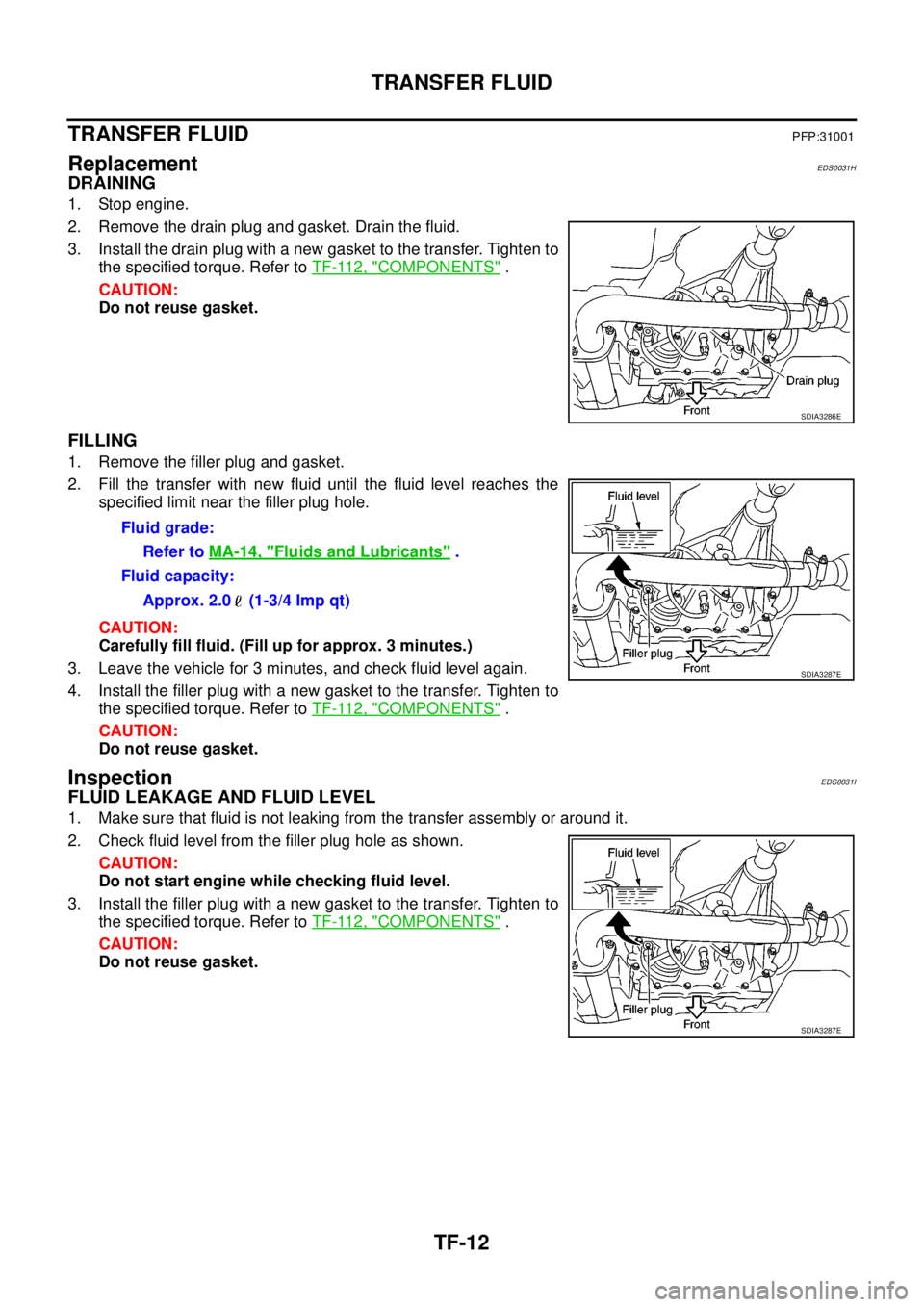
DRAINING
1. Stop engine.
2. Remove the drain plug and gasket. Drain the fluid.
3. Install the drain plug with a new gasket to the transfer. Tighten to
the specified torque. Refer toTF-112, "
COMPONENTS".
CAUTION:
Do not reuse gasket.
FILLING
1. Remove the filler plug and gasket.
2. Fill the transfer with new fluid until the fluid level reaches the
specified limit near the filler plug hole.
CAUTION:
Carefully fill fluid. (Fill up for approx. 3 minutes.)
3. Leave the vehicle for 3 minutes, and check fluid level again.
4. Install the filler plug with a new gasket to the transfer. Tighten to
the specified torque. Refer toTF-112, "
COMPONENTS".
CAUTION:
Do not reuse gasket.
InspectionEDS0031I
FLUID LEAKAGE AND FLUID LEVEL
1. Make sure that fluid is not leaking from the transfer assembly or around it.
2. Check fluid level from the filler plug hole as shown.
CAUTION:
Do not start engine while checking fluid level.
3. Install the filler plug with a new gasket to the transfer. Tighten to
the specified torque. Refer toTF-112, "
COMPONENTS".
CAUTION:
Do not reuse gasket.
SDIA3286E
Fluid grade:
Refer toMA-14, "
Fluids and Lubricants".
Fluid capacity:
Approx. 2.0 (1-3/4 Imp qt)
SDIA3287E
SDIA3287E
Page 3024 of 3171
TROUBLE DIAGNOSIS FOR SYSTEM
TF-57
C
E
F
G
H
I
J
K
L
MA
B
TF
DIAGNOSTIC PROCEDURE
1.CHECK 4LO POSITION SWITCH SIGNAL
With CONSULT-II
1. Start engine.
2. Select “DATA MONITOR” mode for “ALL MODE AWD/4WD” with CONSULT-II.
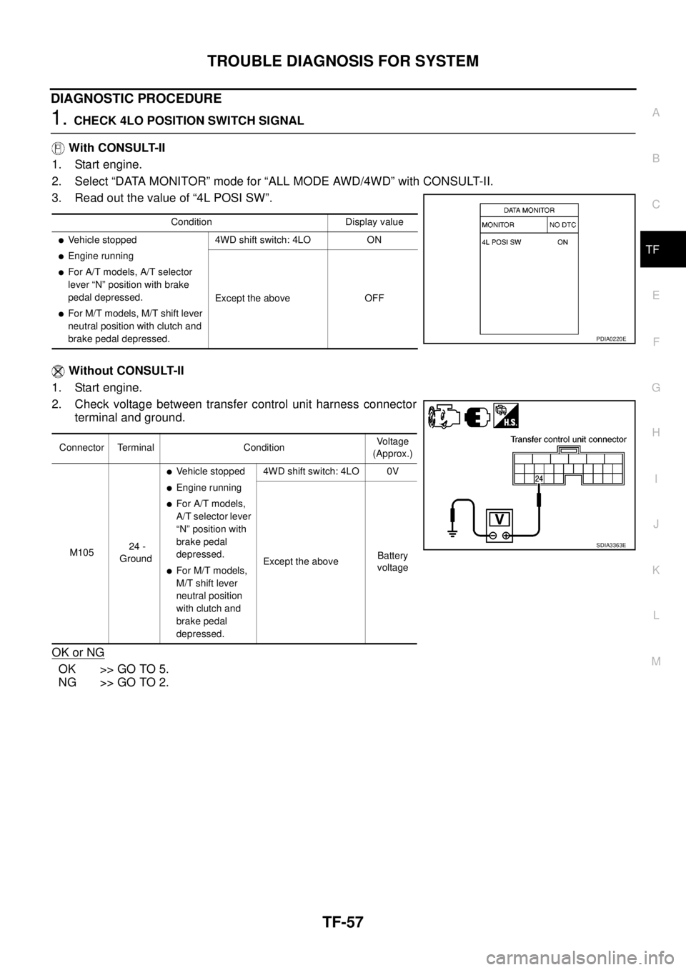
3. Read out the value of “4L POSI SW”.
Without CONSULT-II
1. Start engine.
2. Check voltage between transfer control unit harness connector
terminal and ground.
OK or NG
OK >> GO TO 5.
NG >> GO TO 2.
Condition Display value
lVehicle stopped
lEngine running
lFor A/T models, A/T selector
lever “N” position with brake
pedal depressed.
lFor M/T models, M/T shift lever
neutral position with clutch and
brake pedal depressed.4WD shift switch: 4LO ON
Except the above OFF
PDIA0220E
Connector Terminal ConditionVo l ta g e
(Approx.)
M10524 -
Ground
lVehicle stopped
lEngine running
lFor A/T models,
A/T selector lever
“N” position with
brake pedal
depressed.
lFor M/T models,
M/T shift lever
neutral position
with clutch and
brake pedal
depressed.4WD shift switch: 4LO 0V
Except the aboveBattery
voltage
SDIA3363E
Page 3031 of 3171
TF-64
TROUBLE DIAGNOSIS FOR SYSTEM
DIAGNOSTIC PROCEDURE
1.CHECK WAIT DETECTION SWITCH SIGNAL
With CONSULT-II
1. Start engine.
2. Select “DATA MONITOR” mode for “ALL MODE AWD/4WD” with CONSULT-II.
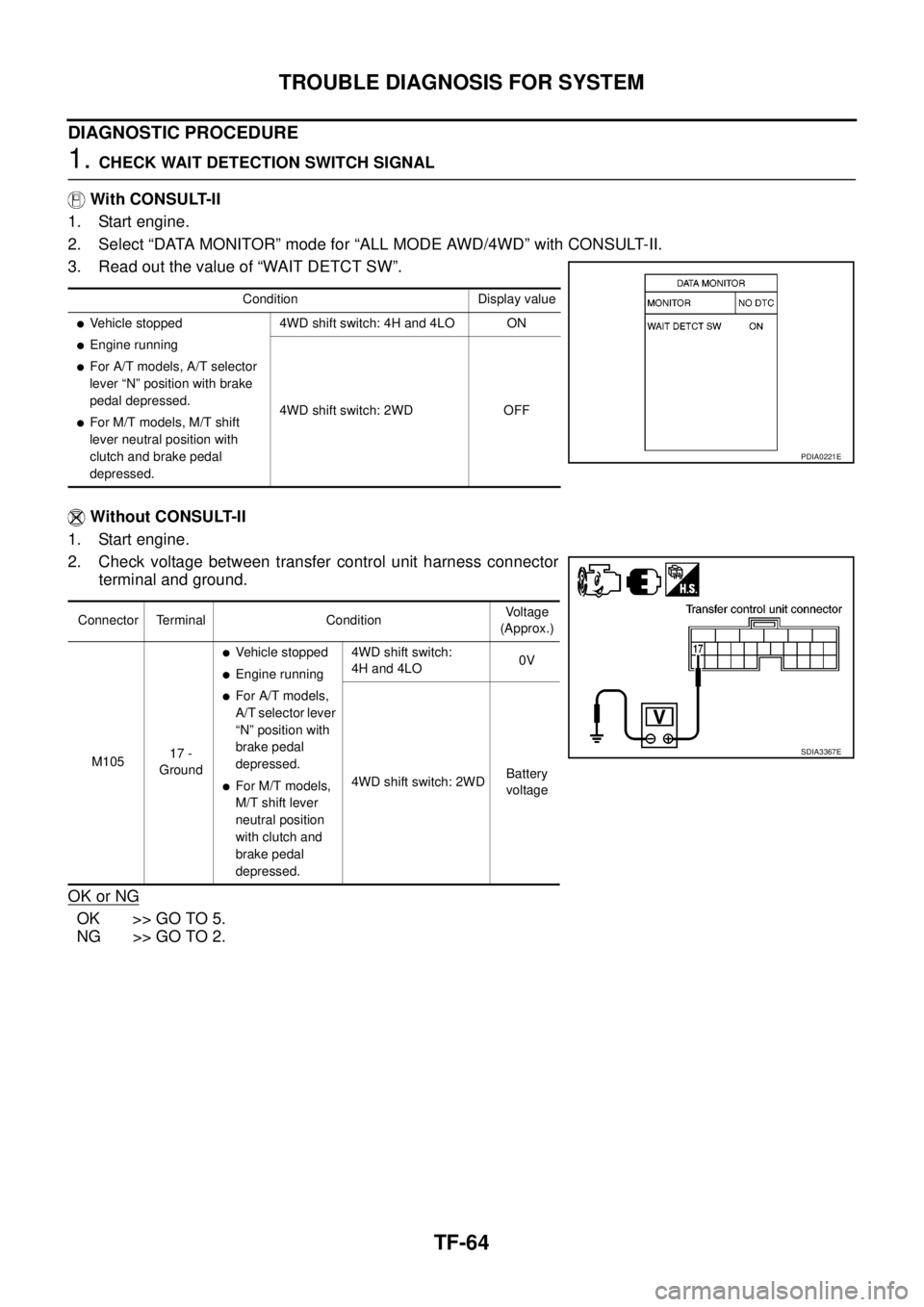
3. Read out the value of “WAIT DETCT SW”.
Without CONSULT-II
1. Start engine.
2. Check voltage between transfer control unit harness connector
terminal and ground.
OK or NG
OK >> GO TO 5.
NG >> GO TO 2.
Condition Display value
lVehicle stopped
lEngine running
lFor A/T models, A/T selector
lever “N” position with brake
pedal depressed.
lFor M/T models, M/T shift
lever neutral position with
clutch and brake pedal
depressed.4WD shift switch: 4H and 4LO ON
4WD shift switch: 2WD OFF
PDIA0221E
Connector Terminal ConditionVoltage
(Approx.)
M10517 -
Ground
lVehicle stopped
lEngine running
lFor A/T models,
A/T selector lever
“N” position with
brake pedal
depressed.
lFor M/T models,
M/T shift lever
neutral position
withclutchand
brake pedal
depressed.4WD shift switch:
4H and 4LO0V
4WD shift switch: 2WDBattery
voltage
SDIA3367E
Page 3035 of 3171
TF-68
TROUBLE DIAGNOSIS FOR SYSTEM
DIAGNOSTIC PROCEDURE
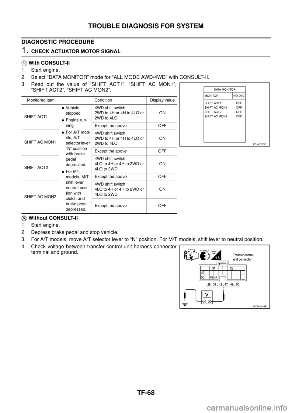
1.CHECK ACTUATOR MOTOR SIGNAL
With CONSULT-II
1. Start engine.
2. Select “DATA MONITOR” mode for “ALL MODE AWD/4WD” with CONSULT-II.
3. Read out the value of “SHIFT ACT1”, “SHIFT AC MON1”,
“SHIFT ACT2”, “SHIFT AC MON2”.
Without CONSULT-II
1. Start engine.
2. Depress brake pedal and stop vehicle.
3. For A/T models, move A/T selector lever to “N” position. For M/T models, shift lever to neutral position.
4. Check voltage between transfer control unit harness connector
terminal and ground.
Monitored item Condition Display value
SHIFT ACT1
lVehicle
stopped
lEngine run-
ning
lFor A/T mod-
els, A/T
selector lever
“N” position
with brake
pedal
depressed.
lFor M/T
models, M/T
shift lever
neutral posi-
tion with
clutch and
brake pedal
depressed.4WD shift switch:
2WD to 4H or 4H to 4LO or
2WD to 4LOON
Except the above OFF
SHIFT AC MON14WD shift switch:
2WD to 4H or 4H to 4LO or
2WD to 4LOON
Except the above OFF
SHIFT ACT24WD shift switch:
4LOto4Hor4Hto2WDor
4LO to 2WDON
Except the above OFF
SHIFT AC MON24WD shift switch:
4LOto4Hor4Hto2WDor
4LO to 2WDON
Except the above OFF
PDIA0223E
WDIA0144E
Page 3043 of 3171
TF-76
TROUBLE DIAGNOSIS FOR SYSTEM
DIAGNOSTIC PROCEDURE
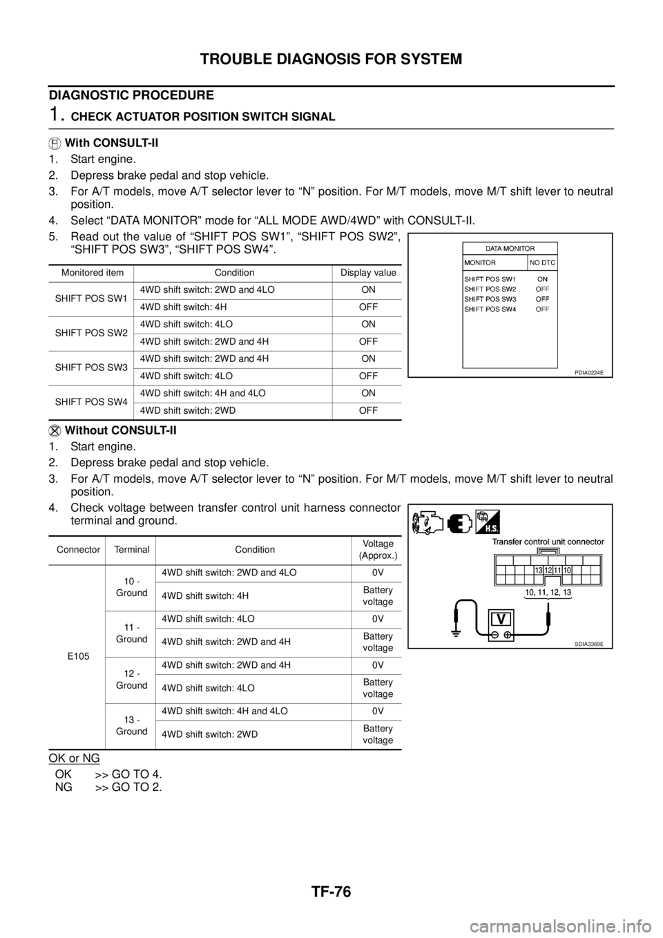
1.CHECK ACTUATOR POSITION SWITCH SIGNAL
With CONSULT-II
1. Start engine.
2. Depress brake pedal and stop vehicle.
3. For A/T models, move A/T selector lever to “N” position. For M/T models, move M/T shift lever to neutral
position.
4. Select “DATA MONITOR” mode for “ALL MODE AWD/4WD” with CONSULT-II.
5. Read out the value of “SHIFT POS SW1”, “SHIFT POS SW2”,
“SHIFT POS SW3”, “SHIFT POS SW4”.
Without CONSULT-II
1. Start engine.
2. Depress brake pedal and stop vehicle.
3. For A/T models, move A/T selector lever to “N” position. For M/T models, move M/T shift lever to neutral
position.
4. Check voltage between transfer control unit harness connector
terminal and ground.
OK or NG
OK >> GO TO 4.
NG >> GO TO 2.
Monitored item Condition Display value
SHIFT POS SW14WD shift switch: 2WD and 4LO ON
4WD shift switch: 4H OFF
SHIFT POS SW24WD shift switch: 4LO ON
4WD shift switch: 2WD and 4H OFF
SHIFT POS SW34WD shift switch: 2WD and 4H ON
4WD shift switch: 4LO OFF
SHIFT POS SW44WD shift switch: 4H and 4LO ON
4WD shift switch: 2WD OFF
Connector Terminal ConditionVoltage
(Approx.)
E10510 -
Ground4WD shift switch: 2WD and 4LO 0V
4WD shift switch: 4HBattery
voltage
11 -
Ground4WD shift switch: 4LO 0V
4WD shift switch: 2WD and 4HBattery
voltage
12 -
Ground4WD shift switch: 2WD and 4H 0V
4WD shift switch: 4LOBattery
voltage
13 -
Ground4WD shift switch: 4H and 4LO 0V
4WD shift switch: 2WDBattery
voltage
PDIA0224E
SDIA3369E
Page 3049 of 3171
TF-82
TROUBLE DIAGNOSIS FOR SYSTEM
CAN Communication Line
EDS0032A
DIAGNOSTIC PROCEDURE
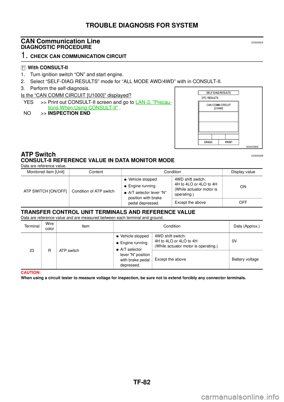
1.CHECK CAN COMMUNICATION CIRCUIT
With CONSULT-II
1. Turn ignition switch “ON” and start engine.
2. Select “SELF-DIAG RESULTS” mode for “ALL MODE AWD/4WD” with in CONSULT-II.
3. Perform the self-diagnosis.
Is the
“CAN COMM CIRCUIT [U1000]”displayed?
YES >> Print out CONSULT-II screen and go toLAN-3, "Precau-
tions When Using CONSULT-II".
NO >>INSPECTION END
AT P S w i t c hEDS0032B
CONSULT-II REFERENCE VALUE IN DATA MONITOR MODE
Data are reference value.
TRANSFER CONTROL UNIT TERMINALS AND REFERENCE VALUE
Data are reference value and are measured between each terminal and ground.
CAUTION:
When using a circuit tester to measure voltage for inspection, be sure not to extend forcibly any connector terminals.
SDIA2390E
Monitored item [Unit] Content Condition Display value
ATP SWITCH [ON/OFF] Condition of ATP switch
lVehicle stopped
lEngine running
lA/T selector lever “N”
position with brake
pedal depressed.4WD shift switch:
4H to 4LO or 4LO to 4H
(While actuator motor is
operating.)ON
Except the above OFF
Te r m i n a lWire
colorItem Condition Data (Approx.)
23 R ATP switch
lVehicle stopped
lEngine running
lA/T selector
lever “N” position
with brake pedal
depressed.4WD shift switch:
4H to 4LO or 4LO to 4H
(While actuator motor is operating.)0V
Except the above Battery voltage
Page 3050 of 3171
TROUBLE DIAGNOSIS FOR SYSTEM
TF-83
C
E
F
G
H
I
J
K
L
MA
B
TF
DIAGNOSTIC PROCEDURE
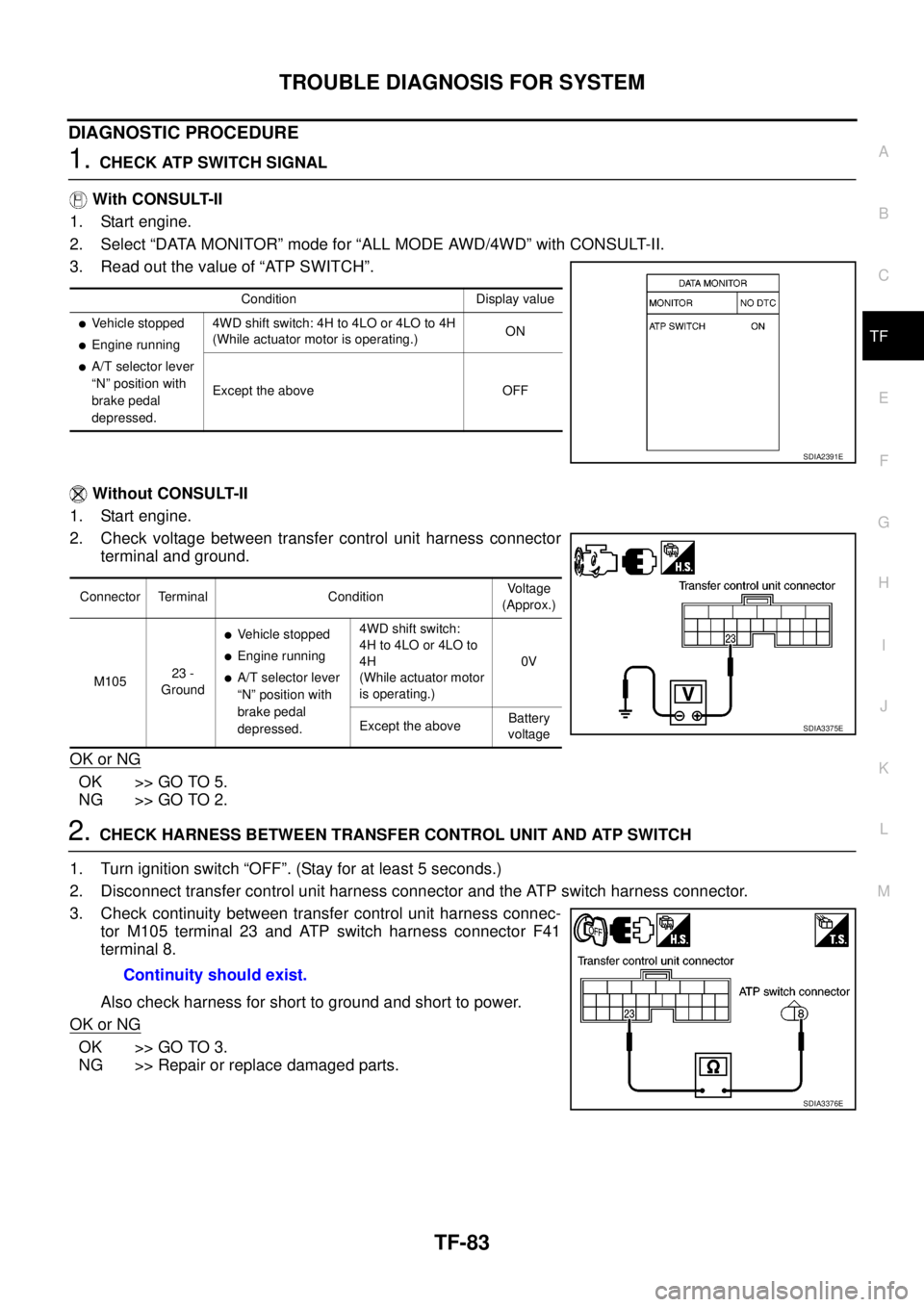
1.CHECK ATP SWITCH SIGNAL
With CONSULT-II
1. Start engine.
2. Select “DATA MONITOR” mode for “ALL MODE AWD/4WD” with CONSULT-II.
3. Read out the value of “ATP SWITCH”.
Without CONSULT-II
1. Start engine.
2. Check voltage between transfer control unit harness connector
terminal and ground.
OK or NG
OK >> GO TO 5.
NG >> GO TO 2.
2.CHECK HARNESS BETWEEN TRANSFER CONTROL UNIT AND ATP SWITCH
1. Turn ignition switch “OFF”. (Stay for at least 5 seconds.)
2. Disconnect transfer control unit harness connector and the ATP switch harness connector.
3. Check continuity between transfer control unit harness connec-
tor M105 terminal 23 and ATP switch harness connector F41
terminal 8.
Also check harness for short to ground and short to power.
OK or NG
OK >> GO TO 3.
NG >> Repair or replace damaged parts.
Condition Display value
lVehicle stopped
lEngine running
lA/T selector lever
“N” position with
brake pedal
depressed.4WD shift switch: 4H to 4LO or 4LO to 4H
(While actuator motor is operating.)ON
Except the above OFF
SDIA2391E
Connector Terminal ConditionVoltage
(Approx.)
M10523 -
Ground
lVehicle stopped
lEngine running
lA/T selector lever
“N” position with
brake pedal
depressed.4WD shift switch:
4H to 4LO or 4LO to
4H
(While actuator motor
is operating.)0V
Except the aboveBattery
voltage
SDIA3375E
Continuity should exist.
SDIA3376E