Page 1460 of 3171
EM-78
SECONDARY TIMING CHAIN
Summary of the inspection items:
*1: Transmission/transaxle/CVT fluid, power steering fluid, brake fluid, etc.
*2: Check engine oil level 10 minutes after engine stopped.Item Before starting engine Engine running After engine stopped
Engine coolant Level Leakage Level
Engine oil Level Leakage Level (*2)
Other oils and fluid (*1) Level Leakage Level
Fuel Leakage Leakage Leakage
Exhaust gases — Leakage —
Page 1473 of 3171
PRIMARY TIMING CHAIN
EM-91
C
D
E
F
G
H
I
J
K
L
MA
EM
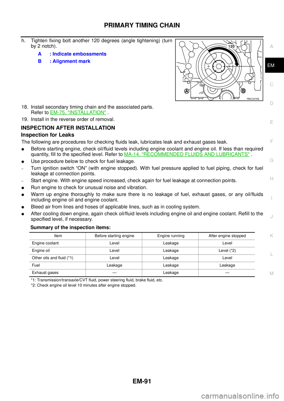
h. Tighten fixing bolt another 120 degrees (angle tightening) (turn
by 2 notch).
18. Install secondary timing chain and the associated parts.
Refer toEM-75, "
INSTALLATION".
19. Install in the reverse order of removal.
INSPECTION AFTER INSTALLATION
Inspection for Leaks
The following are procedures for checking fluids leak, lubricates leak and exhaust gases leak.
lBefore starting engine, check oil/fluid levels including engine coolant and engine oil. If less than required
quantity, fill to the specified level. Refer toMA-14, "
RECOMMENDED FLUIDS AND LUBRICANTS".
lUse procedure below to check for fuel leakage.
–Turn ignition switch “ON” (with engine stopped). With fuel pressure applied to fuel piping, check for fuel
leakage at connection points.
–Start engine. With engine speed increased, check again for fuel leakage at connection points.
lRun engine to check for unusual noise and vibration.
lWarm up engine thoroughly to make sure there is no leakage of fuel, exhaust gases, or any oil/fluids
including engine oil and engine coolant.
lBleed air from lines and hoses of applicable lines, such as in cooling system.
lAfter cooling down engine, again check oil/fluid levels including engine oil and engine coolant. Refill to the
specified level, if necessary.
Summary of the inspection items:
*1: Transmission/transaxle/CVT fluid, power steering fluid, brake fluid, etc.
*2: Check engine oil level 10 minutes after engine stopped.
A : Indicate embossments
B : Alignment mark
PBIC3476E
Item Before starting engine Engine running After engine stopped
Engine coolant Level Leakage Level
Engine oil Level Leakage Level (*2)
Other oils and fluid (*1) Level Leakage Level
Fuel Leakage Leakage Leakage
Exhaust gases — Leakage —
Page 1474 of 3171
EM-92
CYLINDER HEAD
CYLINDER HEAD
PFP:11041
On-Vehicle ServiceEBS01E6A
CHECKING COMPRESSION PRESSURE
1. Warm up engine thoroughly. Then, stop it.
2. Using CONSULT-II, make sure no error codes are indicated for self-diagnosis items. Refer toEC-38,
"Basic Inspection".
lDo not disconnect CONSULT-II until the end of this operation; it will be used to check engine rpm and
for error detection at the end of this operation.
3. Disconnect the battery cable from the negative terminal.
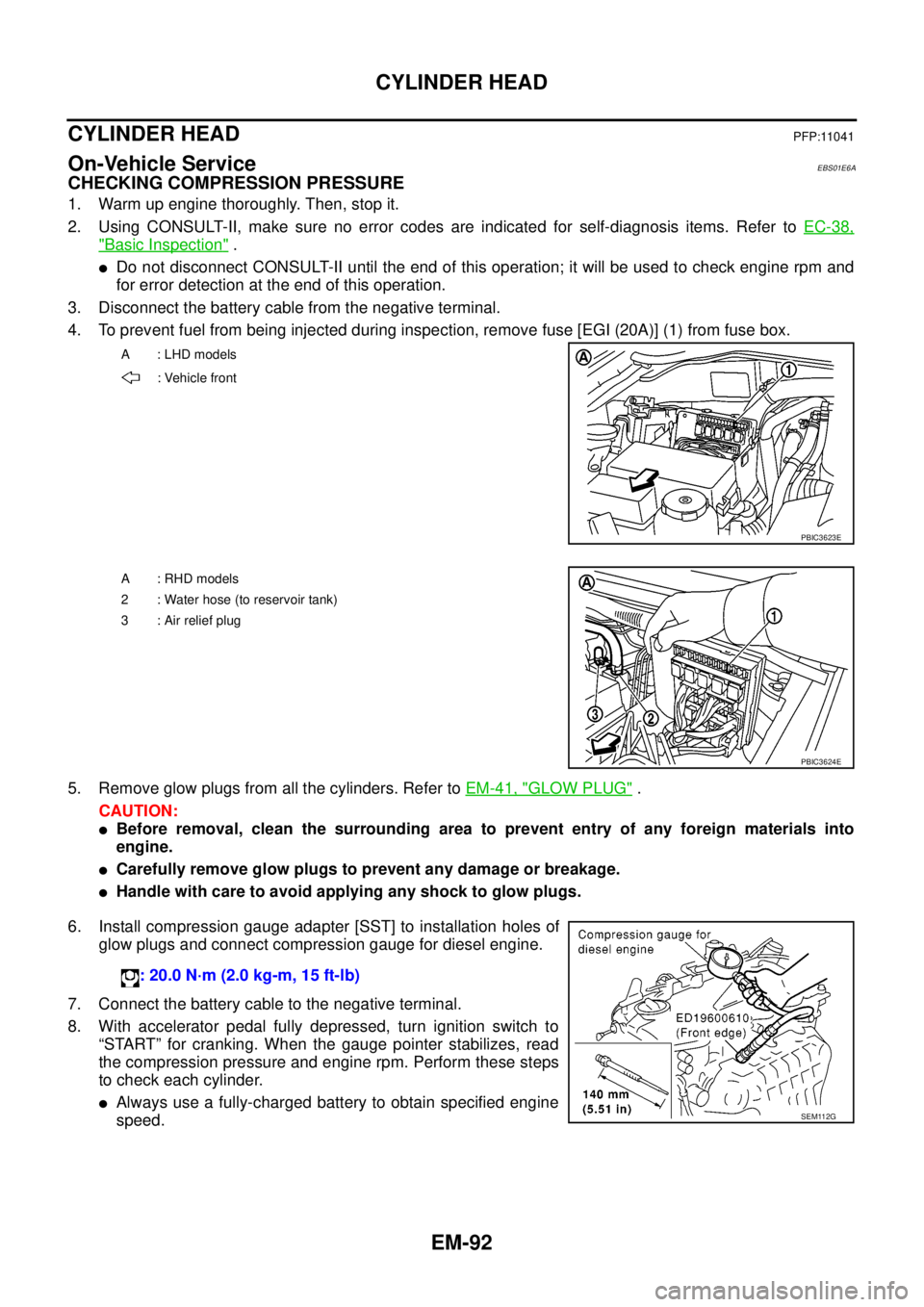
4. To prevent fuel from being injected during inspection, remove fuse [EGI (20A)] (1) from fuse box.
5. Remove glow plugs from all the cylinders. Refer toEM-41, "
GLOW PLUG".
CAUTION:
lBefore removal, clean the surrounding area to prevent entry of any foreign materials into
engine.
lCarefully remove glow plugs to prevent any damage or breakage.
lHandle with care to avoid applying any shock to glow plugs.
6. Install compression gauge adapter [SST] to installation holes of
glow plugs and connect compression gauge for diesel engine.
7. Connect the battery cable to the negative terminal.
8. With accelerator pedal fully depressed, turn ignition switch to
“START” for cranking. When the gauge pointer stabilizes, read
the compression pressure and engine rpm. Perform these steps
to check each cylinder.
lAlways use a fully-charged battery to obtain specified engine
speed.
A : LHD models
: Vehicle front
PBIC3623E
A : RHD models
2 : Water hose (to reservoir tank)
3:Airreliefplug
PBIC3624E
: 20.0 N·m (2.0 kg-m, 15 ft-lb)
SEM112G
Page 1480 of 3171
EM-98
CYLINDER HEAD
lBefore installing, remove carbon depositing on mounting hole of glow plug with a reamer.
6. Install engine coolant temperature sensor.
7. Install in the reverse order of removal.
INSPECTION AFTER INSTALLATION
Inspection for Leaks
The following are procedures for checking fluids leak, lubricates leak and exhaust gases leak.
lBefore starting engine, check oil/fluid levels including engine coolant and engine oil. If less than required
quantity, fill to the specified level. Refer toMA-14, "
RECOMMENDED FLUIDS AND LUBRICANTS".
lUse procedure below to check for fuel leakage.
–Turn ignition switch “ON” (with engine stopped). With fuel pressure applied to fuel piping, check for fuel
leakage at connection points.
–Start engine. With engine speed increased, check again for fuel leakage at connection points.
lRun engine to check for unusual noise and vibration.
lWarm up engine thoroughly to make sure there is no leakage of fuel, exhaust gases, or any oil/fluids
including engine oil and engine coolant.
lBleed air from lines and hoses of applicable lines, such as in cooling system.
lAfter cooling down engine, again check oil/fluid levels including engine oil and engine coolant. Refill to the
specified level, if necessary.
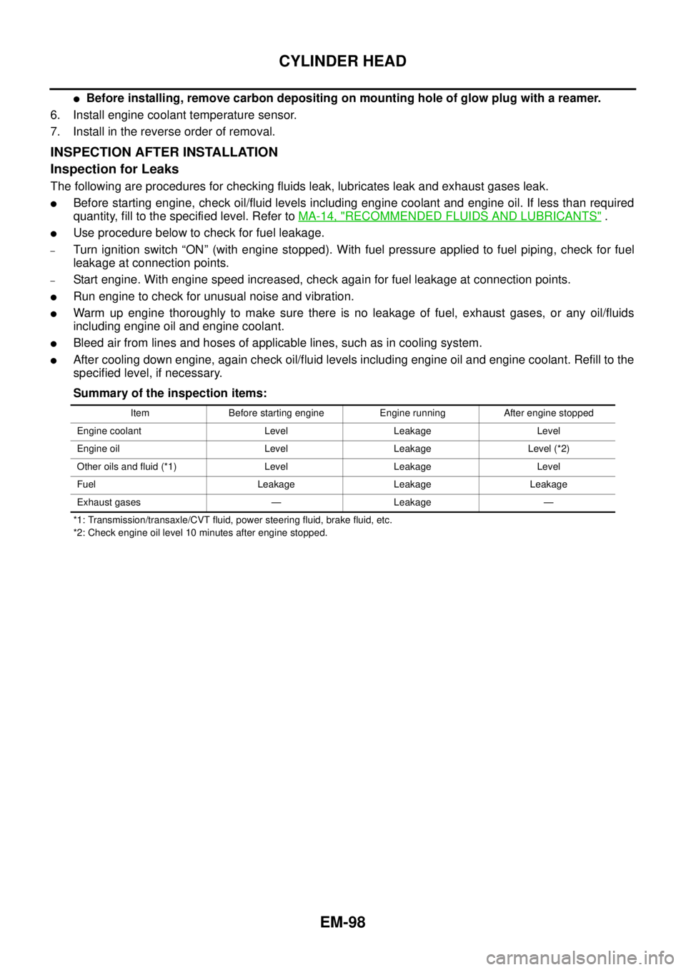
Summary of the inspection items:
*1: Transmission/transaxle/CVT fluid, power steering fluid, brake fluid, etc.
*2: Check engine oil level 10 minutes after engine stopped.Item Before starting engine Engine running After engine stopped
Engine coolant Level Leakage Level
Engine oil Level Leakage Level (*2)
Other oils and fluid (*1) Level Leakage Level
Fuel Leakage Leakage Leakage
Exhaust gases — Leakage —
Page 1485 of 3171
CYLINDER HEAD
EM-103
C
D
E
F
G
H
I
J
K
L
MA
EM
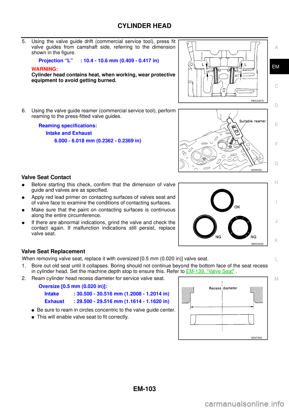
5. Using the valve guide drift (commercial service tool), press fit
valve guides from camshaft side, referring to the dimension
showninthefigure.
WARNING:
Cylinder head contains heat, when working, wear protective
equipment to avoid getting burned.
6. Using the valve guide reamer (commercial service tool), perform
reaming to the press-fitted valve guides.
Valve Seat Contact
lBefore starting this check, confirm that the dimension of valve
guide and valves are as specified.
lApply red lead primer on contacting surfaces of valves seat and
of valve face to examine the conditions of contacting surfaces.
lMake sure that the paint on contacting surfaces is continuous
along the entire circumference.
lIf there are abnormal indications, grind the valve and check the
contact again. If malfunction indications still persist, replace
valve seat.
Valve Seat Replacement
When removing valve seat, replace it with oversized [0.5 mm (0.020 in)] valve seat.
1. Bore out old seat until it collapses. Boring should not continue beyond the bottom face of the seat recess
in cylinder head. Set the machine depth stop to ensure this. Refer toEM-139, "
Valve Seat".
2. Ream cylinder head recess diameter for service valve seat.
lBe sure to ream in circles concentric to the valve guide center.
lThis will enable valve seat to fit correctly.Projection “L” : 10.4 - 10.6 mm (0.409 - 0.417 in)
PBIC2497E
Reaming specifications:
Intake and Exhaust
6.000 - 6.018 mm (0.2362 - 0.2369 in)
SEM932C
SBIA0322E
Oversize [0.5 mm (0.020 in)]:
Intake : 30.500 - 30.516 mm (1.2008 - 1.2014 in)
Exhaust : 29.500 - 29.516 mm (1.1614 - 1.1620 in)
SEM795A
Page 1490 of 3171
EM-108
ENGINE ASSEMBLY
Removal
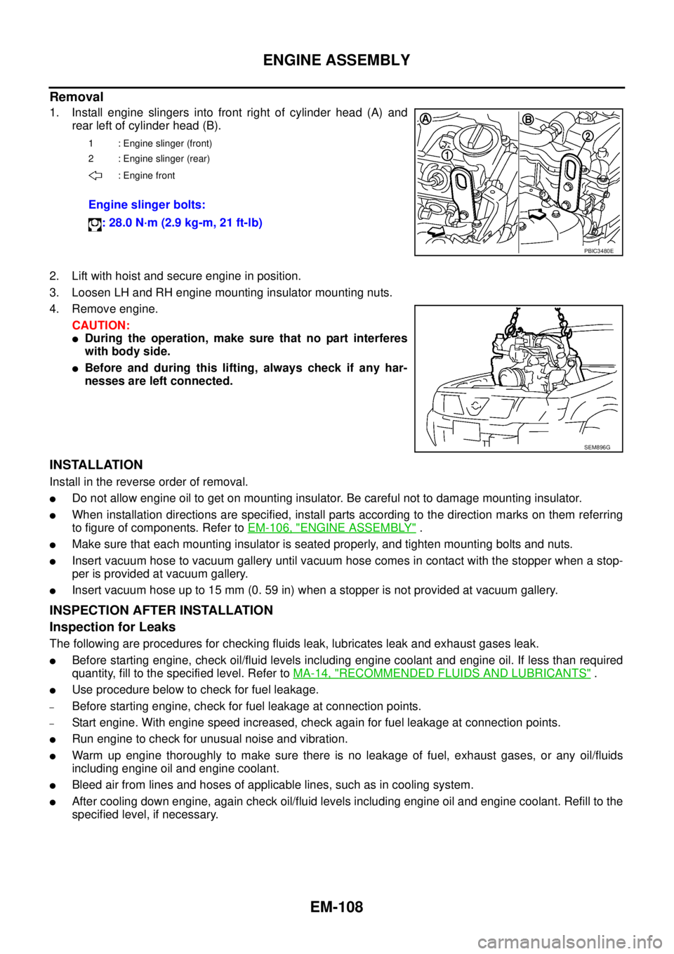
1. Install engine slingers into front right of cylinder head (A) and
rear left of cylinder head (B).
2. Lift with hoist and secure engine in position.
3. Loosen LH and RH engine mounting insulator mounting nuts.
4. Remove engine.
CAUTION:
lDuring the operation, make sure that no part interferes
with body side.
lBefore and during this lifting, always check if any har-
nesses are left connected.
INSTALLATION
Install in the reverse order of removal.
lDo not allow engine oil to get on mounting insulator. Be careful not to damage mounting insulator.
lWhen installation directions are specified, install parts according to the direction marks on them referring
to figure of components. Refer toEM-106, "
ENGINE ASSEMBLY".
lMake sure that each mounting insulator is seated properly, and tighten mounting bolts and nuts.
lInsert vacuum hose to vacuum gallery until vacuum hose comes in contact with the stopper when a stop-
per is provided at vacuum gallery.
lInsert vacuum hose up to 15 mm (0. 59 in) when a stopper is not provided at vacuum gallery.
INSPECTION AFTER INSTALLATION
Inspection for Leaks
The following are procedures for checking fluids leak, lubricates leak and exhaust gases leak.
lBefore starting engine, check oil/fluid levels including engine coolant and engine oil. If less than required
quantity, fill to the specified level. Refer toMA-14, "
RECOMMENDED FLUIDS AND LUBRICANTS".
lUse procedure below to check for fuel leakage.
–Before starting engine, check for fuel leakage at connection points.
–Start engine. With engine speed increased, check again for fuel leakage at connection points.
lRun engine to check for unusual noise and vibration.
lWarm up engine thoroughly to make sure there is no leakage of fuel, exhaust gases, or any oil/fluids
including engine oil and engine coolant.
lBleed air from lines and hoses of applicable lines, such as in cooling system.
lAfter cooling down engine, again check oil/fluid levels including engine oil and engine coolant. Refill to the
specified level, if necessary.
1 : Engine slinger (front)
2 : Engine slinger (rear)
: Engine front
Engine slinger bolts:
: 28.0 N·m (2.9 kg-m, 21 ft-lb)
PBIC3480E
SEM896G
Page 1491 of 3171
ENGINE ASSEMBLY
EM-109
C
D
E
F
G
H
I
J
K
L
MA
EM
Summary of the inspection items:
*1: Transmission/transaxle/AT fluid, power steering fluid, brake fluid, etc.
*2: Check engine oil level 10 minutes after engine stopped.Item Before starting engine Engine running After engine stopped
Engine coolant Level Leakage Level
Engine oil Level Leakage Level (*2)
Other oils and fluid (*1) Level Leakage Level
Fuel Leakage Leakage Leakage
Exhaust gases — Leakage —
Page 1554 of 3171
FFD-8
DIFFERENTIAL GEAR OIL
DIFFERENTIAL GEAR OIL
PFP:KLD30
Changing Differential Gear OilEDS00351
DRAINING
1. Stop the engine.
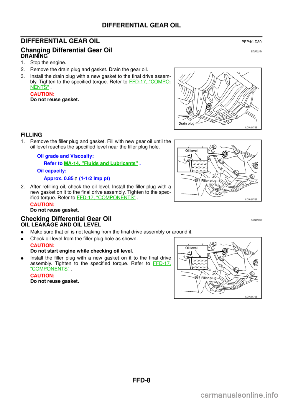
2. Remove the drain plug and gasket. Drain the gear oil.
3. Install the drain plug with a new gasket to the final drive assem-
bly. Tighten to the specified torque. Refer toFFD-17, "
COMPO-
NENTS".
CAUTION:
Do not reuse gasket.
FILLING
1. Remove the filler plug and gasket. Fill with new gear oil until the
oil level reaches the specified level near the filler plug hole.
2. After refilling oil, check the oil level. Install the filler plug with a
new gasket on it to the final drive assembly. Tighten to the spec-
ified torque. Refer toFFD-17, "
COMPONENTS".
CAUTION:
Do not reuse gasket.
Checking Differential Gear OilEDS00352
OIL LEAKAGE AND OIL LEVEL
lMake sure that oil is not leaking from the final drive assembly or around it.
lCheck oil level from the filler plug hole as shown.
CAUTION:
Do not start engine while checking oil level.
lInstall the filler plug with a new gasket on it to the final drive
assembly. Tighten to the specified torque. Refer toFFD-17,
"COMPONENTS".
CAUTION:
Do not reuse gasket.
LDIA0175E
Oil grade and Viscosity:
Refer toMA-14, "
Fluids and Lubricants".
Oil capacity:
Approx. 0.85 (1-1/2 Imp pt)
LDIA0176E
LDIA0176E