2005 NISSAN NAVARA stop start
[x] Cancel search: stop startPage 1589 of 3171
FUEL FILTER
FL-5
C
D
E
F
G
H
I
J
K
L
MA
FL
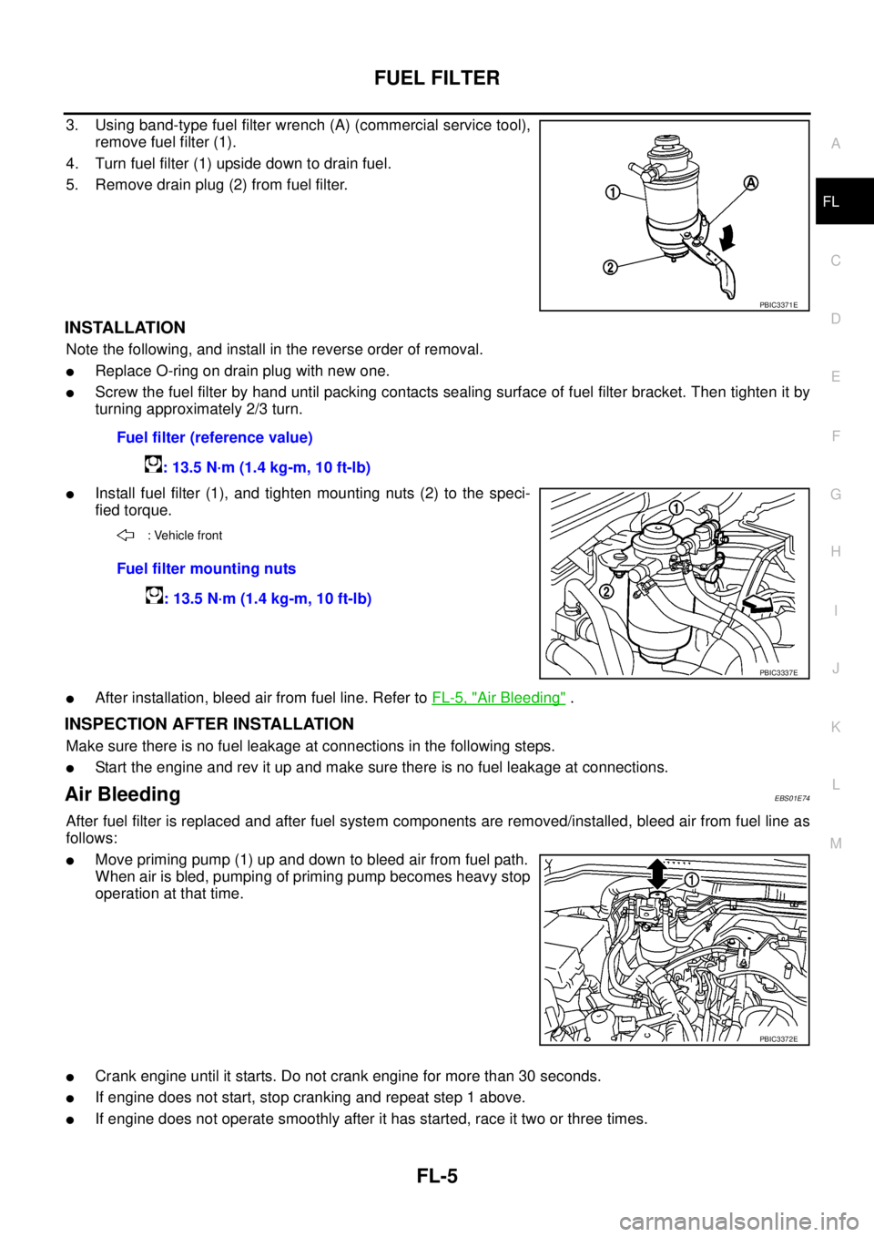
3. Using band-type fuel filter wrench (A) (commercial service tool),
remove fuel filter (1).
4. Turn fuel filter (1) upside down to drain fuel.
5. Remove drain plug (2) from fuel filter.
INSTALLATION
Note the following, and install in the reverse order of removal.
lReplace O-ring on drain plug with new one.
lScrew the fuel filter by hand until packing contacts sealing surface of fuel filter bracket. Then tighten it by
turning approximately 2/3 turn.
lInstall fuel filter (1), and tighten mounting nuts (2) to the speci-
fied torque.
lAfter installation, bleed air from fuel line. Refer toFL-5, "Air Bleeding".
INSPECTION AFTER INSTALLATION
Make sure there is no fuel leakage at connections in the following steps.
lStart the engine and rev it up and make sure there is no fuel leakage at connections.
Air BleedingEBS01E74
After fuel filter is replaced and after fuel system components are removed/installed, bleed air from fuel line as
follows:
lMove priming pump (1) up and down to bleed air from fuel path.
When air is bled, pumping of priming pump becomes heavy stop
operation at that time.
lCrank engine until it starts. Do not crank engine for more than 30 seconds.
lIf engine does not start, stop cranking and repeat step 1 above.
lIf engine does not operate smoothly after it has started, race it two or three times.
PBIC3371E
Fuel filter (reference value)
: 13.5 N·m (1.4 kg-m, 10 ft-lb)
: Vehicle front
Fuel filter mounting nuts
: 13.5 N·m (1.4 kg-m, 10 ft-lb)
PBIC3337E
PBIC3372E
Page 1693 of 3171
SQUEAK AND RATTLE TROUBLE DIAGNOSES
GW-7
C
D
E
F
G
H
J
K
L
MA
B
GW
FELT CLOTHTAPE
Used to insulate where movement does not occur. Ideal for instrument panel applications.
68370-4B000: 15´25 mm (0.59´0.98 in) pad/68239-13E00: 5 mm (0.20 in) wide tape roll
The following materials, not available through NISSAN Parts Department, can also be used to repair squeaks
and rattles.
UHMW(TEFLON) TAPE
Insulates where slight movement is present. Ideal for instrument panel applications.
SILICONE GREASE
Used in place of UHMW tape that will be visible or not fit.
Note: Will only last a few months.
SILICONE SPRAY
Use when grease cannot be applied.
DUCT TAPE
Usetoeliminatemovement.
CONFIRM THE REPAIR
Confirm that the cause of a noise is repaired by test driving the vehicle. Operate the vehicle under the same
conditions as when the noise originally occurred. Refer to the notes on the Diagnostic Worksheet.
Generic Squeak and Rattle TroubleshootingEIS00C03
Refer to Table of Contents for specific component removal and installation information.
INSTRUMENT PANEL
Most incidents are caused by contact and movement between:
1. Cluster lid A and instrument panel
2. Acrylic lens and combination meter housing
3. Instrument panel to front pillar garnish
4. Instrument panel to windshield
5. Instrument panel mounting pins
6. Wiring harnesses behind the combination meter
7. A/C defroster duct and duct joint
These incidents can usually be located by tapping or moving the components to duplicate the noise or by
pressing on the components while driving to stop the noise. Most of these incidents can be repaired by
applying felt cloth tape or silicon spray (in hard to reach areas). Urethane pads can be used to insulate
wiring harness.
CAUTION:
Do not use silicone spray to isolate a squeak or rattle. If you saturate the area with silicone, you
will not be able to recheck the repair.
CENTER CONSOLE
Components to pay attention to include:
1. Shifter assembly cover to finisher
2. A/C control unit and cluster lid C
3. Wiring harnesses behind audio and A/C control unit
The instrument panel repair and isolation procedures also apply to the center console.
DOORS
Pay attention to the:
1. Finisher and inner panel making a slapping noise
2. Inside handle escutcheon to door finisher
3. Wiring harnesses tapping
4. Door striker out of alignment causing a popping noise on starts and stops
Tapping or moving the components or pressing on them while driving to duplicate the conditions can isolate
many of these incidents. You can usually insulate the areas with felt cloth tape or insulator foam blocks to
repair the noise.
Page 1759 of 3171
IDX-7
A
C
D
E
F
G
H
I
J
K
L B
IDX
ALPHABETICAL INDEX
Starter ................................................................SC-27
Starting system ..................................................SC-27
Steering gear, linkage and transfer gear inspection .....
MA-36
,MA-37
Steering linkage .................................................PS-14
Steering wheel and column .................................PS-8
Step lamp .........................................................LT-145
Stop lamp .........................................................LT-121
Stop lamp switch .............................................EC-330
STOP/L - Wiring diagram .................................LT-121
Striking rod (M/T) ...............................................MT-23
Strut (front) ......................................................FSU-10
Sun roof, electric ................................................RF-10
Sunload sensor ..............................................ATC-112
Sunroof ..................................................RF-10,RF-21
Super lock ...........................................................BL-55
Supplemental Restraint System ........................SRS-6
Symbols and abbreviations .....................GI-10,GI-23
Symptom matrix chart ........................................EC-42
Synchronizer (M/T) ............................................MT-21
T
Tachometer ..........................................................DI-4
Tail lamp ...........................................................LT-125
TAIL/L - Wiring diagram ....................................LT-127
TC boost control solnoid valve ........................EC-309
TC boost sensor ..............................................EC-153
TCC/V - Wiring diagram ..................................EC-311
TCM circuit diagram ..........................................AT-42
TCM inspection table .........................................AT-76
Thermostat ........................................................CO-24
Three way catalyst precautions ............................GI-5
Throttle body ......................................................EM-20
Tie-rod ...............................................................PS-14
Timing chain .........................................EM-73,EM-79
Timing gear ........................................................EM-79
Tire rotation .......................................................MA-34
Tire size ..............................................................GI-60
Torque converter installation ...........................AT-250
Torque convertor clutch solenoid valveAT-110,AT-112
Tow truck towing .................................................GI-53
Towing point .......................................................GI-54
Transfer control device .............TF-74,TF-78,TF-105
Transfer control unit inspection table ..................TF-38
Transfer oil replacement ....................................MA-32
Transfer serial number .......................................GI-58
Transmission case (M/T) ...................................MT-19
Transmission serial number ....................GI-58,GI-59
Tread-FR&RR (Dimensions) ..............................GI-60
Trim .....................................................................EI-33
Trouble diagnoses ..............................................GI-11
Turbine revolution sensor ................................AT-123
Turbocharger .....................................................EM-28
Turbocharger charge air cooler .........................EM-18
Turbocharger precautions ....................................GI-6
TURN - Wiring diagram ....................................LT-100
Turn signal lamp .................................................LT-97
Two-pole lift ........................................................GI-52
V
Vacuum hose drawing (Engine control) .............EC-16
Vacuum pump ...................................................EM-42
Valve clearance ................................................EM-66
Valve guide .....................................................EM-101
Valve lifter .........................................................EM-62
Valve seat .......................................................EM-103
Valve spring ....................................................EM-104
Vanity mirror lamp .............................................LT-145
Vehicle identification number ..............................GI-57
Vehicle recovery (freeing a stuck vehicle) ..........GI-54
VEHSEC - Wiring diagram ...............................BL-143
Viscosity number (SAE) ....................................MA-15
W
Wait detection switch ..............................TF-63
,TF-66
WARN - Wiring diagram .....................................DI-30
Warning chime ....................................................DI-51
Warning lamps ....................................................DI-28
Washer, front .....................................................WW-4
Water pump ......................................................CO-21
Water temperature gauge .....................................DI-4
Wheel alignment (front) .....................................FSU-7
Wheel balance ..................................................MA-34
Wheel bearing (front) .........................................FAX-5
Wheel bearing (rear) .........................................RAX-6
Wheel sensors (ABS) .....................................BRC-37
Wheel size ..........................................................GI-60
Wheelbase (Dimensions) ....................................GI-60
Width (Dimensions) ............................................GI-60
WINDOW - Wiring diagram ...............................GW-20
Window, door ......................................GW-35,GW-38
Window, rear .....................................................GW-43
Windshield ........................................................GW-11
WIPER - Wiring diagram ..................................WW-12
Wiper, front ........................................................WW-4
Wiring Diagram (Cell code) list ..........................PG-68
Wiring diagrams ..................................................GI-15
Page 1765 of 3171

IP-6
SQUEAK AND RATTLE TROUBLE DIAGNOSES
Generic Squeak and Rattle Troubleshooting
EIS00DYX
Refer to Table of Contents for specific component removal and installation information.
INSTRUMENT PANEL
Most incidents are caused by contact and movement between:
1. The cluster lid A and instrument panel
2. Acrylic lens and combination meter housing
3. Instrument panel to front pillar garnish
4. Instrument panel to windshield
5. Instrument panel mounting pins
6. Wiring harnesses behind the combination meter
7. A/C defroster duct and duct joint
These incidents can usually be located by tapping or moving the components to duplicate the noise or by
pressing on the components while driving to stop the noise. Most of these incidents can be repaired by apply-
ing felt cloth tape or silicone spray (in hard to reach areas). Urethane pads can be used to insulate wiring har-
ness.
CAUTION:
Do not use silicone spray to isolate a squeak or rattle. If you saturate the area with silicone, you will
not be able to recheck the repair.
CENTER CONSOLE
Components to pay attention to include:
1. Shifter assembly cover to finisher
2. A/C control unit and cluster lid C
3. Wiring harnesses behind audio and A/C control unit
The instrument panel repair and isolation procedures also apply to the center console.
DOORS
Pay attention to the:
1. Finisher and inner panel making a slapping noise
2. Inside handle escutcheon to door finisher
3. Wiring harnesses tapping
4. Door striker out of alignment causing a popping noise on starts and stops
Tapping or moving the components or pressing on them while driving to duplicate the conditions can isolate
many of these incidents. You can usually insulate the areas with felt cloth tape or insulator foam blocks to
repair the noise.
TRUNK
Trunk noises are often caused by a loose jack or loose items put into the trunk by the owner.
In addition look for:
1. Trunk lid bumpers out of adjustment
2. Trunk lid striker out of adjustment
3. The trunk lid torsion bars knocking together
4. A loose license plate or bracket
Most of these incidents can be repaired by adjusting, securing or insulating the item(s) or component(s) caus-
ing the noise.
Page 2099 of 3171
LT-16
HEADLAMP -CONVENTIONAL TYPE-
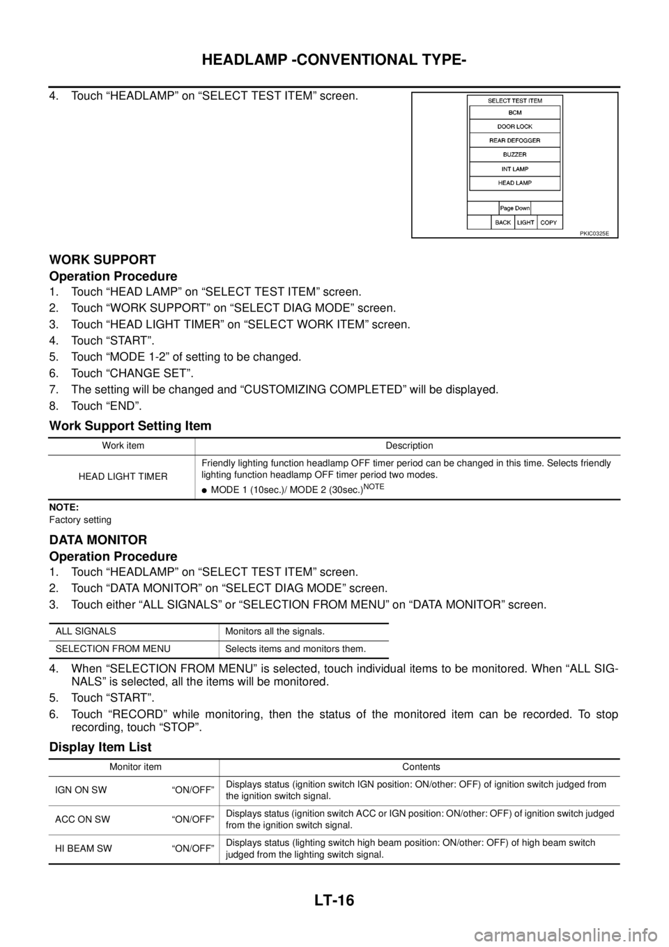
4. Touch “HEADLAMP” on “SELECT TEST ITEM” screen.
WORK SUPPORT
Operation Procedure
1. Touch “HEAD LAMP” on “SELECT TEST ITEM” screen.
2. Touch “WORK SUPPORT” on “SELECT DIAG MODE” screen.
3. Touch “HEAD LIGHT TIMER” on “SELECT WORK ITEM” screen.
4. Touch “START”.
5. Touch “MODE 1-2” of setting to be changed.
6. Touch “CHANGE SET”.
7. The setting will be changed and “CUSTOMIZING COMPLETED” will be displayed.
8. Touch “END”.
Work Support Setting Item
NOTE:
Factory setting
DATA MONITOR
Operation Procedure
1. Touch “HEADLAMP” on “SELECT TEST ITEM” screen.
2. Touch “DATA MONITOR” on “SELECT DIAG MODE” screen.
3. Touch either “ALL SIGNALS” or “SELECTION FROM MENU” on “DATA MONITOR” screen.
4. When “SELECTION FROM MENU” is selected, touch individual items to be monitored. When “ALL SIG-
NALS” is selected, all the items will be monitored.
5. Touch “START”.
6. Touch “RECORD” while monitoring, then the status of the monitored item can be recorded. To stop
recording, touch “STOP”.
Display Item List
PKIC0325E
Work item Description
HEAD LIGHT TIMERFriendly lighting function headlamp OFF timer period can be changed in this time. Selects friendly
lighting function headlamp OFF timer period two modes.
lMODE 1 (10sec.)/ MODE 2 (30sec.)NOTE
ALL SIGNALS Monitors all the signals.
SELECTION FROM MENU Selects items and monitors them.
Monitor item Contents
IGN ON SW “ON/OFF”Displays status (ignition switch IGN position: ON/other: OFF) of ignition switch judged from
the ignition switch signal.
ACCONSW “ON/OFF”Displays status (ignition switch ACC or IGN position: ON/other: OFF) of ignition switch judged
from the ignition switch signal.
HI BEAM SW “ON/OFF”Displays status (lighting switch high beam position: ON/other: OFF) of high beam switch
judged from the lighting switch signal.
Page 2102 of 3171
HEADLAMP -CONVENTIONAL TYPE-
LT-19
C
D
E
F
G
H
I
J
L
MA
B
LT
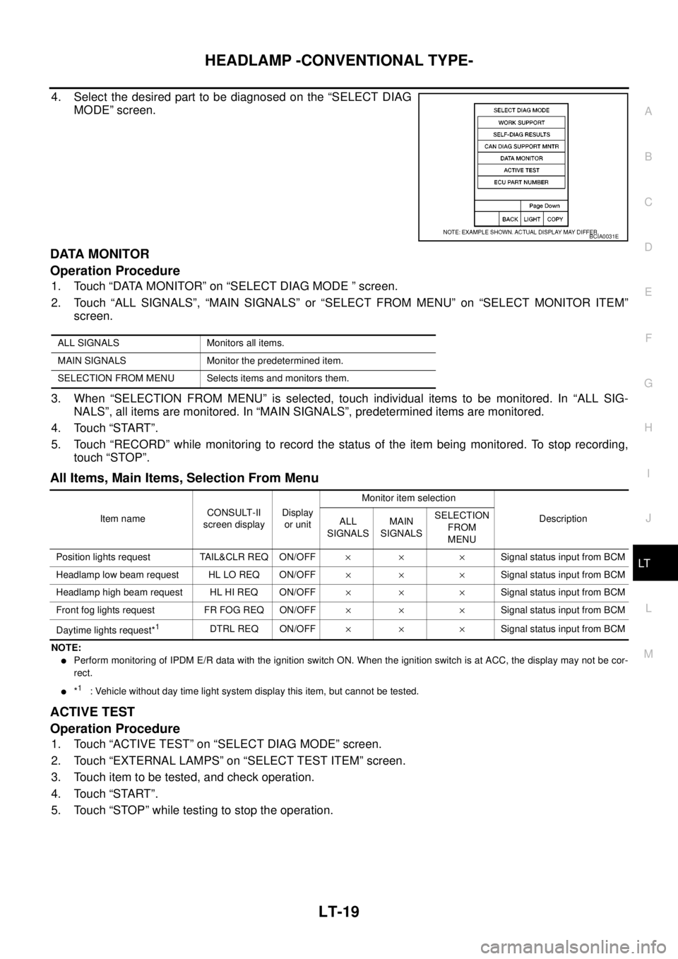
4. Select the desired part to be diagnosed on the “SELECT DIAG
MODE” screen.
DATA MONITOR
Operation Procedure
1. Touch “DATA MONITOR” on “SELECT DIAG MODE ” screen.
2. Touch “ALL SIGNALS”, “MAIN SIGNALS” or “SELECT FROM MENU” on “SELECT MONITOR ITEM”
screen.
3. When “SELECTION FROM MENU” is selected, touch individual items to be monitored. In “ALL SIG-
NALS”, all items are monitored. In “MAIN SIGNALS”, predetermined items are monitored.
4. Touch “START”.
5. Touch “RECORD” while monitoring to record the status of the item being monitored. To stop recording,
touch “STOP”.
All Items, Main Items, Selection From Menu
NOTE:
lPerform monitoring of IPDM E/R data with the ignition switch ON. When the ignition switch is at ACC, the display may not be cor-
rect.
l*1: Vehicle without day time light system display this item, but cannot be tested.
ACTIVE TEST
Operation Procedure
1. Touch “ACTIVE TEST” on “SELECT DIAG MODE” screen.
2. Touch “EXTERNAL LAMPS” on “SELECT TEST ITEM” screen.
3. Touch item to be tested, and check operation.
4. Touch “START”.
5. Touch “STOP” while testing to stop the operation.
BCIA0031E
ALL SIGNALS Monitors all items.
MAIN SIGNALS Monitor the predetermined item.
SELECTION FROM MENU Selects items and monitors them.
Item nameCONSULT-II
screen displayDisplay
or unitMonitor item selection
Description
ALL
SIGNALSMAIN
SIGNALSSELECTION
FROM
MENU
Position lights request TAIL&CLR REQ ON/OFF´´ ´Signal status input from BCM
Headlamp low beam request HL LO REQ ON/OFF´´ ´Signal status input from BCM
Headlamp high beam request HL HI REQ ON/OFF´´ ´Signal status input from BCM
Front fog lights request FR FOG REQ ON/OFF´´ ´Signal status input from BCM
Daytime lights request*
1DTRL REQ ON/OFF´´ ´Signal status input from BCM
Page 2103 of 3171
LT-20
HEADLAMP -CONVENTIONAL TYPE-
Headlamp High Beam Does Not Illuminate (Both Sides)
EKS00P7S
1.CHECK COMBINATION SWITCH INPUT SIGNAL
With CONSULT-II
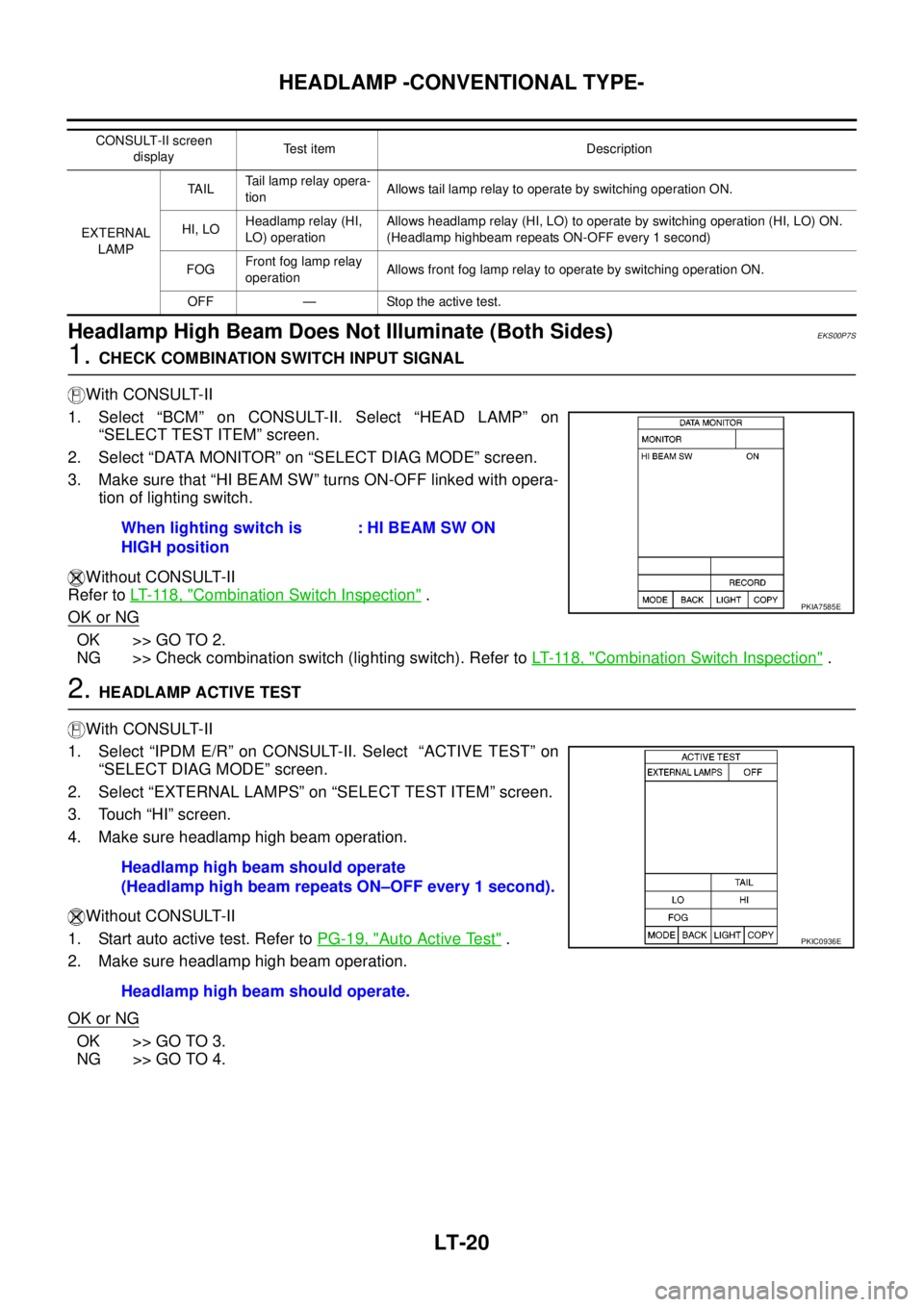
1. Select “BCM” on CONSULT-II. Select “HEAD LAMP” on
“SELECT TEST ITEM” screen.
2. Select “DATA MONITOR” on “SELECT DIAG MODE” screen.
3. Make sure that “HI BEAM SW” turns ON-OFF linked with opera-
tion of lighting switch.
Without CONSULT-II
Refer toLT- 11 8 , "
Combination Switch Inspection".
OK or NG
OK >> GO TO 2.
NG >> Check combination switch (lighting switch). Refer toLT- 11 8 , "
Combination Switch Inspection".
2.HEADLAMP ACTIVE TEST
With CONSULT-II
1. Select “IPDM E/R” on CONSULT-II. Select “ACTIVE TEST” on
“SELECT DIAG MODE” screen.
2. Select “EXTERNAL LAMPS” on “SELECT TEST ITEM” screen.
3. Touch “HI” screen.
4. Make sure headlamp high beam operation.
Without CONSULT-II
1. Start auto active test. Refer toPG-19, "
Auto Active Test".
2. Make sure headlamp high beam operation.
OK or NG
OK >> GO TO 3.
NG >> GO TO 4.
CONSULT-II screen
displayTest item Description
EXTERNAL
LAMPTA I LTail lamp relay opera-
tionAllows tail lamp relay to operate by switching operation ON.
HI, LOHeadlamp relay (HI,
LO) operationAllows headlamp relay (HI, LO) to operate by switching operation (HI, LO) ON.
(Headlamp highbeam repeats ON-OFF every 1 second)
FOGFront fog lamp relay
operationAllows front fog lamp relay to operate by switching operation ON.
OFF — Stop the active test.
When lighting switch is
HIGH position: HI BEAM SW ON
PKIA7585E
Headlamp high beam should operate
(Headlamp high beam repeats ON–OFF every 1 second).
Headlamp high beam should operate.
PKIC0936E
Page 2126 of 3171
HEADLAMP - DAYTIME LIGHT SYSTEM -
LT-43
C
D
E
F
G
H
I
J
L
MA
B
LT
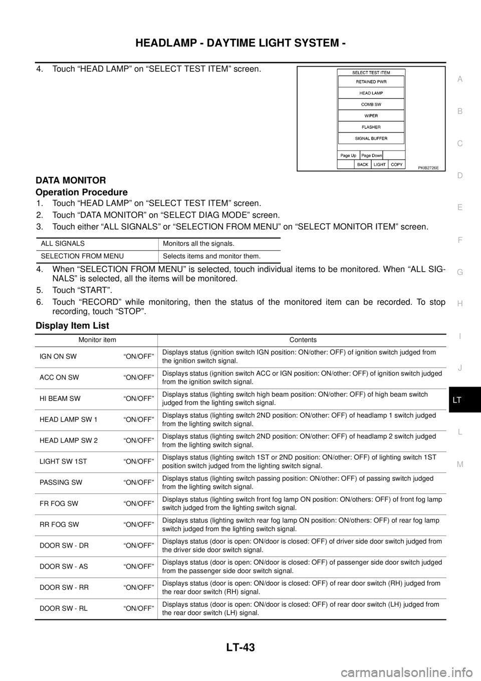
4. Touch “HEAD LAMP” on “SELECT TEST ITEM” screen.
DATA MONITOR
Operation Procedure
1. Touch “HEAD LAMP” on “SELECT TEST ITEM” screen.
2. Touch “DATA MONITOR” on “SELECT DIAG MODE” screen.
3. Touch either “ALL SIGNALS” or “SELECTION FROM MENU” on “SELECT MONITOR ITEM” screen.
4. When “SELECTION FROM MENU” is selected, touch individual items to be monitored. When “ALL SIG-
NALS” is selected, all the items will be monitored.
5. Touch “START”.
6. Touch “RECORD” while monitoring, then the status of the monitored item can be recorded. To stop
recording, touch “STOP”.
Display Item List
PKIB2726E
ALL SIGNALS Monitors all the signals.
SELECTION FROM MENU Selects items and monitor them.
Monitor item Contents
IGN ON SW “ON/OFF”Displays status (ignition switch IGN position: ON/other: OFF) of ignition switch judged from
the ignition switch signal.
ACC ON SW “ON/OFF”Displays status (ignition switch ACC or IGN position: ON/other: OFF) of ignition switch judged
from the ignition switch signal.
HI BEAM SW “ON/OFF”Displays status (lighting switch high beam position: ON/other: OFF) of high beam switch
judged from the lighting switch signal.
HEAD LAMP SW 1 “ON/OFF”Displays status (lighting switch 2ND position: ON/other: OFF) of headlamp 1 switch judged
from the lighting switch signal.
HEAD LAMP SW 2 “ON/OFF”Displays status (lighting switch 2ND position: ON/other: OFF) of headlamp 2 switch judged
from the lighting switch signal.
LIGHT SW 1ST “ON/OFF”Displays status (lighting switch 1ST or 2ND position: ON/other: OFF) of lighting switch 1ST
position switch judged from the lighting switch signal.
PASSING SW “ON/OFF”Displays status (lighting switch passing position: ON/other: OFF) of passing switch judged
from the lighting switch signal.
FR FOG SW “ON/OFF”Displays status (lighting switch front fog lamp ON position: ON/others: OFF) of front fog lamp
switch judged from the lighting switch signal.
RR FOG SW “ON/OFF”Displays status (lighting switch rear fog lamp ON position: ON/others: OFF) of rear fog lamp
switch judged from the lighting switch signal.
DOOR SW - DR “ON/OFF”Displays status (door is open: ON/door is closed: OFF) of driver side door switch judged from
the driver side door switch signal.
DOOR SW - AS “ON/OFF”Displays status (door is open: ON/door is closed: OFF) of passenger side door switch judged
from the passenger side door switch signal.
DOOR SW - RR “ON/OFF”Displays status (door is open: ON/door is closed: OFF) of rear door switch (RH) judged from
the rear door switch (RH) signal.
DOOR SW - RL “ON/OFF”Displays status (door is open: ON/door is closed: OFF) of rear door switch (LH) judged from
the rear door switch (LH) signal.