2005 NISSAN NAVARA stop start
[x] Cancel search: stop startPage 1037 of 3171
![NISSAN NAVARA 2005 Repair Workshop Manual TROUBLE DIAGNOSIS
EC-57
C
D
E
F
G
H
I
J
K
L
MA
EC71 LTurbocharger boost sensor
ground[Ignition switch ON]Approximately 0.3V
72 BRRefrigerant pressure sensor
ground[Engine is running]
lWarm-up conditio NISSAN NAVARA 2005 Repair Workshop Manual TROUBLE DIAGNOSIS
EC-57
C
D
E
F
G
H
I
J
K
L
MA
EC71 LTurbocharger boost sensor
ground[Ignition switch ON]Approximately 0.3V
72 BRRefrigerant pressure sensor
ground[Engine is running]
lWarm-up conditio](/manual-img/5/57362/w960_57362-1036.png)
TROUBLE DIAGNOSIS
EC-57
C
D
E
F
G
H
I
J
K
L
MA
EC71 LTurbocharger boost sensor
ground[Ignition switch ON]Approximately 0.3V
72 BRRefrigerant pressure sensor
ground[Engine is running]
lWarm-up condition
lIdle speedApproximately 0.3V
73 B Mass air flow sensor ground[Ignition switch ON]Approximately 0.3V
74 RIntake air temperature sen-
sor ground[Ignition switch ON]Approximately 0.3V
82 WAccelerator pedal position
sensor 1 power supply[Ignition switch ON]Approximately 5.3V
83 RAccelerator pedal position
sensor 1[Ignition switch ON]
lEngine: Stopped
lAccelerator pedal: Fully released0.95 - 1.17V
[Ignition switch ON]
lEngine: Stopped
lAccelerator pedal: Fully depressedMore than 4.6V
84 BAccelerator pedal position
sensor 1 ground[Ignition switch ON]Approximately 0.3V
85 —Sensor ground
(Accelerator pedal position
sensor shield circuit)[Ignition switch ON]Approximately 0.3V
87 P CAN communication line[Ignition switch ON]Approximately 2.0 - 2.6V
Output voltage varies with the
communication status.
89 SB Data link connector[Ignition switch ON]
lCONSULT-II: DisconnectedApproximately 0V - Battery volt-
age (11 - 14V)
90 WAccelerator pedal position
sensor 2 power supply[Ignition switch ON]Approximately 5.3V
91 RAccelerator pedal position
sensor 2[Ignition switch ON]
lEngine: Stopped
lAccelerator pedal: Fully released0.58 - 0.78V
[Ignition switch ON]
lEngine: Stopped
lAccelerator pedal: Fully depressedMore than 2.3V
92 BAccelerator pedal position
sensor 2 ground[Ignition switch ON]Approximately 0.3V
95 L CAN communication line[Ignition switch ON]Approximately 2.6 - 3.2V
Output voltage varies with the
communication status.
99 V Start signal[Ignition switch ON]Approximately 0.3V
[Ignition switch START]BATTERY VOLTAGE
(11 - 14V)
100 V Stop lamp switch[Ignition switch OFF]
lBrake pedal: Fully releasedApproximately 0V
[Ignition switch OFF]
lBrake pedal: Slightly depressedBATTERY VOLTAGE
(11 - 14V) TERMI-
NAL
NO.WIRE
COLORITEM CONDITIONDATA
(DC Voltage and Pulse Signal)
Page 1043 of 3171
![NISSAN NAVARA 2005 Repair Workshop Manual TROUBLE DIAGNOSIS
EC-63
C
D
E
F
G
H
I
J
K
L
MA
ECACT CR PRESS [MPa]´´
lThe Fuel rail pressure (determined by
the signal voltage of the fuel rail pres-
sure sensor) is displayed.
BATTERY VOLT [V]´´ NISSAN NAVARA 2005 Repair Workshop Manual TROUBLE DIAGNOSIS
EC-63
C
D
E
F
G
H
I
J
K
L
MA
ECACT CR PRESS [MPa]´´
lThe Fuel rail pressure (determined by
the signal voltage of the fuel rail pres-
sure sensor) is displayed.
BATTERY VOLT [V]´´](/manual-img/5/57362/w960_57362-1042.png)
TROUBLE DIAGNOSIS
EC-63
C
D
E
F
G
H
I
J
K
L
MA
ECACT CR PRESS [MPa]´´
lThe Fuel rail pressure (determined by
the signal voltage of the fuel rail pres-
sure sensor) is displayed.
BATTERY VOLT [V]´´
lThe power supply voltage of ECM is
displayed.
P/N POSI SW [ON/OFF]´´
lIndicates [ON/OFF] condition from the
park/neutral position switch signal.
START SIGNAL [ON/OFF]´´
lIndicates [ON/OFF] condition from the
starter signal.
AIR COND SIG [ON/OFF]´´
lIndicates [ON/OFF] condition of the air
conditioner switch as determined by
the air conditioner signal.
BRAKE SW [ON/OFF]´´
lIndicates [ON/OFF] condition from the
stop lamp switch signal.
BRAKE SW2 [ON/OFF]´´
lIndicates [ON/OFF] condition from the
ASCD brake switch and ASCD clutch
switch signal.
IGN SW [ON/OFF]´´
lIndicates [ON/OFF] condition from
ignition switch signal.
WARM UP SW [ON/OFF]´
lIndicates [ON/OFF] condition from
heat up switch signal.
MAS AIR/FL SE [V]´´
lThe signal voltage of the mass air flow
sensor is displayed.This signal is converted by ECM inter-
nally. Thus, these differ from ECM termi-
nals voltage.
MAIN INJ WID [msec]´
lIndicates the actual fuel injection pulse
width compensated by ECM according
to the input signals.
PUMP CURRENT [mA]´
lIndicates the fuel pump power supply
current from the ECM.
GLOW RLY [ON/OFF]´
lThe glow relay control condition
(determined by ECM according to the
input signal) is displayed.
COOLING FAN
[LOW/HI/OFF]´
lIndicates the control condition of the
cooling fans (determined by ECM
according to the input signal).
LOW ... Operates at low speed
HI ... Operates at high speed
OFF ... Stopped
EGR VOL CON/V [step]´
lIndicates the EGR volume control
value computed by the ECM accord-
ing to the input signals.
lThe opening becomes larger as the
value increases.
INT/A VOLUME [mg/]
lThe intake air volume computed from
the mass air flow sensor signal is dis-
played.
BARO SEN [kPa]´´
lThe barometric pressure (determined
by the signal voltage from the absolute
pressure sensor built into the ECM) is
displayed. MONITOR ITEMECM
INPUT
SIG-
NALMAIN
SIG-
NALSCONDITION SPECIFICATION
Page 1047 of 3171

TROUBLE DIAGNOSIS
EC-67
C
D
E
F
G
H
I
J
K
L
MA
EC
P/N POSI SWlIgnition switch: ONShift lever:
P or N (A/T), Neutral (M/T)ON
Except above OFF
START SIGNAL
lIgnition switch: ON®START®ON OFF®ON®OFF
AIRCONDSIG
lEngine: After warming up, idle
the engineAir conditioner switch: OFF OFF
Air conditioner switch: ON
(Compressor operates.)ON
BRAKE SW
lIgnition switch: ONBrake pedal: Fully released OFF
Brake pedal: Slightly depressed ON
BRAKE SW2
lIgnition switch: ON
lBrake pedal: Fully released (A/T)
lClutch pedal and brake pedal:
Fully released (M/T)OFF
lBrake pedal: Slightly depressed
(A/T)
lClutch pedal and/or brake pedal:
Slightly depressed (M/T)ON
IGN SW
lIgnition switch: ON®OFF ON®OFF
WARM UP SW
lIgnition switch: ONHeat up switch: OFF OFF
Heat up switch: ON ON
MAS AIR/FL SE*
lEngine: After warming up
lAir conditioner switch: OFF
lShift lever:
P or N (A/T), Neutral (M/T)
lNo loadIgnition switch: ON
(Engine stopped)Approximately 0.4V
Idle 1.3 - 1.7V
Engine is revving from idle to about
4,000 rpm.1.3 - 1.7V to Approximately 4.0V
(Check for liner voltage rise in
response to engine being
increased to about 4,000 rpm)
MAIN INJ WID
lEngine: After warming up
lShift lever:
P or N (A/T), Neutral (M/T)
lIdle speedNo load 0.50 - 0.70 msec
Blower fan switch: ON
Rear window defogger switch: ON0.50 - 0.80 msec
PUMP CURRENT
lEngine: After warming up
lAir conditioner switch: OFF
lShift lever:
P or N (A/T), Neutral (M/T)
lNo loadIdle 1,600 - 2,000 mA
2,000 rpm 1,500 - 1,900 mA
GLOW RLY Refer toEC-295, "
GLOW CONTROL SYSTEM".
COOLING FAN
lEngine: After warming up, idle
the engine
lAir conditioner switch: OFFEngine coolant temperature:
97°C (207°F) or lessOFF
Engine coolant temperature:
Between 98°C(208°F) and 104°C
(219°F)LOW
Engine coolant temperature:
105°C(221°F) or moreHI
EGR VOL CON/V
lEngine: After warming up
lAir conditioner switch: OFF
lShift lever:
P or N (A/T), Neutral (M/T)
lNo loadAfter 1 minute at idle More than 10 steps
Revving engine from idle to 3,200
rpm0step
INT/A VOLUME
lEngine: After warming up, idle the engine 150 - 450 mg/ MONITOR ITEM CONDITION SPECIFICATION
Page 1070 of 3171

EC-90
DTC P0093 FUEL SYSTEM
5.REPLACE FUEL PUMP
1. Replace fuel pump.
2. Perform Fuel Pump Learning Value Clearing. Refer toEC-24, "
Fuel Pump Learning Value Clearing".
>>INSPECTION END
Component InspectionEBS01KDT
FUEL RAIL PRESSURE RELIEF VALVE
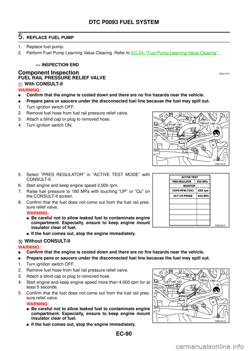
With CONSULT-II
WARNING:
lConfirm that the engine is cooled down and there are no fire hazards near the vehicle.
lPrepare pans or saucers under the disconnected fuel line because the fuel may spill out.
1. Turn ignition switch OFF.
2. Remove fuel hose from fuel rail pressure relief valve.
3. Attach a blind cap or plug to removed hose.
4. Turn ignition switch ON.
5. Select “PRES REGULATOR” in “ACTIVE TEST MODE” with
CONSULT-II.
6. Start engine and keep engine speed 2,000 rpm.
7. Raisefuelpressureto180MPawithtouching“UP”or“Qu”on
the CONSULT-II screen.
8. Confirm that the fuel does not come out from the fuel rail pres-
sure relief valve.
WARNING:
lBe careful not to allow leaked fuel to contaminate engine
compartment. Especially, ensure to keep engine mount
insulator clear of fuel.
lIf the fuel comes out, stop the engine immediately.
Without CONSULT-II
WARNING:
lConfirm that the engine is cooled down and there are no fire hazards near the vehicle.
lPrepare pans or saucers under the disconnected fuel line because the fuel may spill out.
1. Turn ignition switch OFF.
2. Remove fuel hose from fuel rail pressure relief valve.
3. Attach a blind cap or plug to removed hose.
4. Start engine and keep engine speed more than 4,000 rpm for at
least 5 seconds.
5. Confirm that the fuel does not come out from the fuel rail pres-
sure relief valve.
WARNING:
lBe careful not to allow leaked fuel to contaminate engine
compartment. Especially, ensure to keep engine mount
insulator clear of fuel.
lIf the fuel comes out, stop the engine immediately.
PBIB1941E
PBIB0587E
PBIB1941E
Page 1077 of 3171

DTC P0102, P0103 MAF SENSOR
EC-97
C
D
E
F
G
H
I
J
K
L
MA
EC
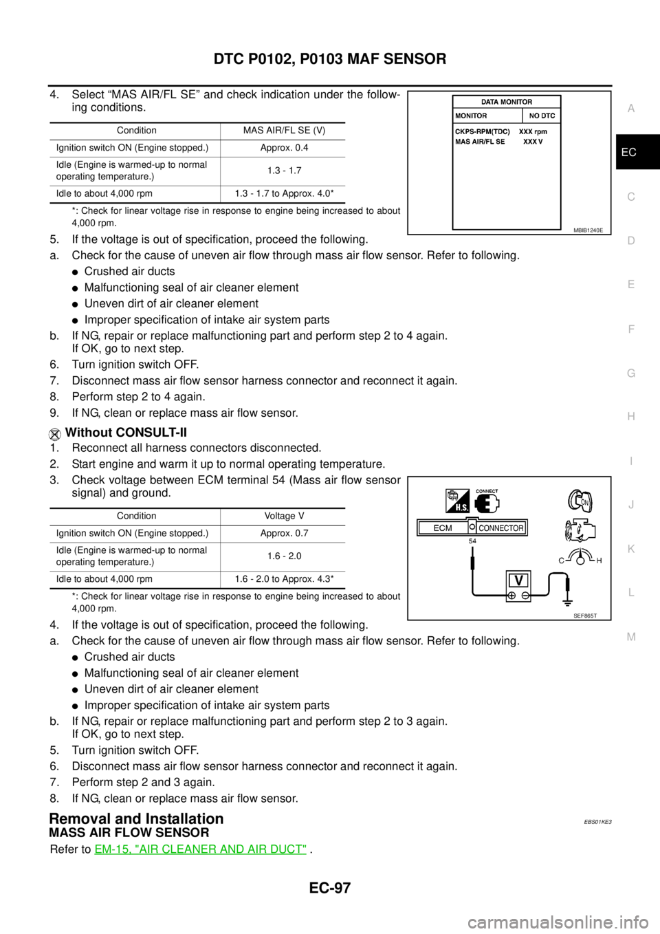
4. Select “MAS AIR/FL SE” and check indication under the follow-
ing conditions.
*: Check for linear voltage rise in response to engine being increased to about
4,000 rpm.
5. If the voltage is out of specification, proceed the following.
a. Check for the cause of uneven air flow through mass air flow sensor. Refer to following.
lCrushed air ducts
lMalfunctioning seal of air cleaner element
lUneven dirt of air cleaner element
lImproper specification of intake air system parts
b. If NG, repair or replace malfunctioning part and perform step 2 to 4 again.
IfOK,gotonextstep.
6. Turn ignition switch OFF.
7. Disconnect mass air flow sensor harness connector and reconnect it again.
8. Performstep2to4again.
9. If NG, clean or replace mass air flow sensor.
Without CONSULT-II
1. Reconnect all harness connectors disconnected.
2. Start engine and warm it up to normal operating temperature.
3. Check voltage between ECM terminal 54 (Mass air flow sensor
signal) and ground.
*: Check for linear voltage rise in response to engine being increased to about
4,000 rpm.
4. If the voltage is out of specification, proceed the following.
a. Check for the cause of uneven air flow through mass air flow sensor. Refer to following.
lCrushed air ducts
lMalfunctioning seal of air cleaner element
lUneven dirt of air cleaner element
lImproper specification of intake air system parts
b. If NG, repair or replace malfunctioning part and perform step 2 to 3 again.
IfOK,gotonextstep.
5. Turn ignition switch OFF.
6. Disconnect mass air flow sensor harness connector and reconnect it again.
7. Perform step 2 and 3 again.
8. If NG, clean or replace mass air flow sensor.
Removal and InstallationEBS01KE3
MASS AIR FLOW SENSOR
Refer toEM-15, "AIR CLEANER AND AIR DUCT".
Condition MAS AIR/FL SE (V)
Ignition switch ON (Engine stopped.) Approx. 0.4
Idle (Engine is warmed-up to normal
operating temperature.)1.3 - 1.7
Idle to about 4,000 rpm 1.3 - 1.7 to Approx. 4.0*
MBIB1240E
Condition Voltage V
Ignition switch ON (Engine stopped.) Approx. 0.7
Idle (Engine is warmed-up to normal
operating temperature.)1.6 - 2.0
Idle to about 4,000 rpm 1.6 - 2.0 to Approx. 4.3*
SEF865T
Page 1170 of 3171

EC-190
DTC P0504 ASCD BRAKE SWITCH
On Board Diagnosis Logic
EBS01KHW
The MI will not light up for this diagnosis.
DTC confirmation ProcedureEBS01KHX
CAUTION:
Always drive vehicle at a safe speed.
NOTE:
If DTC Confirmation Procedure has been previously conducted, always turn ignition switch OFF and wait at
least 10 seconds before conducting the next test.
TESTING CONDITION:
Steps 3 and 4 may be conducted with the drive wheels lifted in the shop or by driving the vehicle. If a
road test is expected to be easier, it is unnecessary to lift the vehicle.
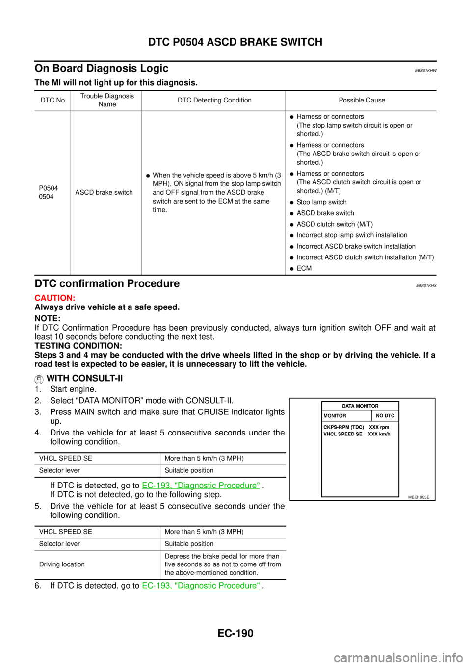
WITH CONSULT-II
1. Start engine.
2. Select “DATA MONITOR” mode with CONSULT-II.
3. Press MAIN switch and make sure that CRUISE indicator lights
up.
4. Drive the vehicle for at least 5 consecutive seconds under the
following condition.
If DTC is detected, go toEC-193, "
Diagnostic Procedure".
If DTC is not detected, go to the following step.
5. Drive the vehicle for at least 5 consecutive seconds under the
following condition.
6. If DTC is detected, go toEC-193, "
Diagnostic Procedure".
DTC No.Trouble Diagnosis
NameDTC Detecting Condition Possible Cause
P0504
0504ASCD brake switch
lWhen the vehicle speed is above 5 km/h (3
MPH), ON signal from the stop lamp switch
and OFF signal from the ASCD brake
switch are sent to the ECM at the same
time.
lHarness or connectors
(The stop lamp switch circuit is open or
shorted.)
lHarness or connectors
(The ASCD brake switch circuit is open or
shorted.)
lHarness or connectors
(The ASCD clutch switch circuit is open or
shorted.) (M/T)
lStop lamp switch
lASCD brake switch
lASCD clutch switch (M/T)
lIncorrectstoplampswitchinstallation
lIncorrect ASCD brake switch installation
lIncorrect ASCD clutch switch installation (M/T)
lECM
VHCL SPEED SE More than 5 km/h (3 MPH)
Selector lever Suitable position
VHCL SPEED SE More than 5 km/h (3 MPH)
Selector lever Suitable position
Driving locationDepress the brake pedal for more than
five seconds so as not to come off from
the above-mentioned condition.
MBIB1085E
Page 1282 of 3171

EC-302
EGR VOLUME CONTROL SYSTEM
EGR VOLUME CONTROL SYSTEM
PFP:14710
DescriptionEBS01KLR
SYSTEM DESCRIPTION
*: This signal is sent to the ECM through CAN communication line.
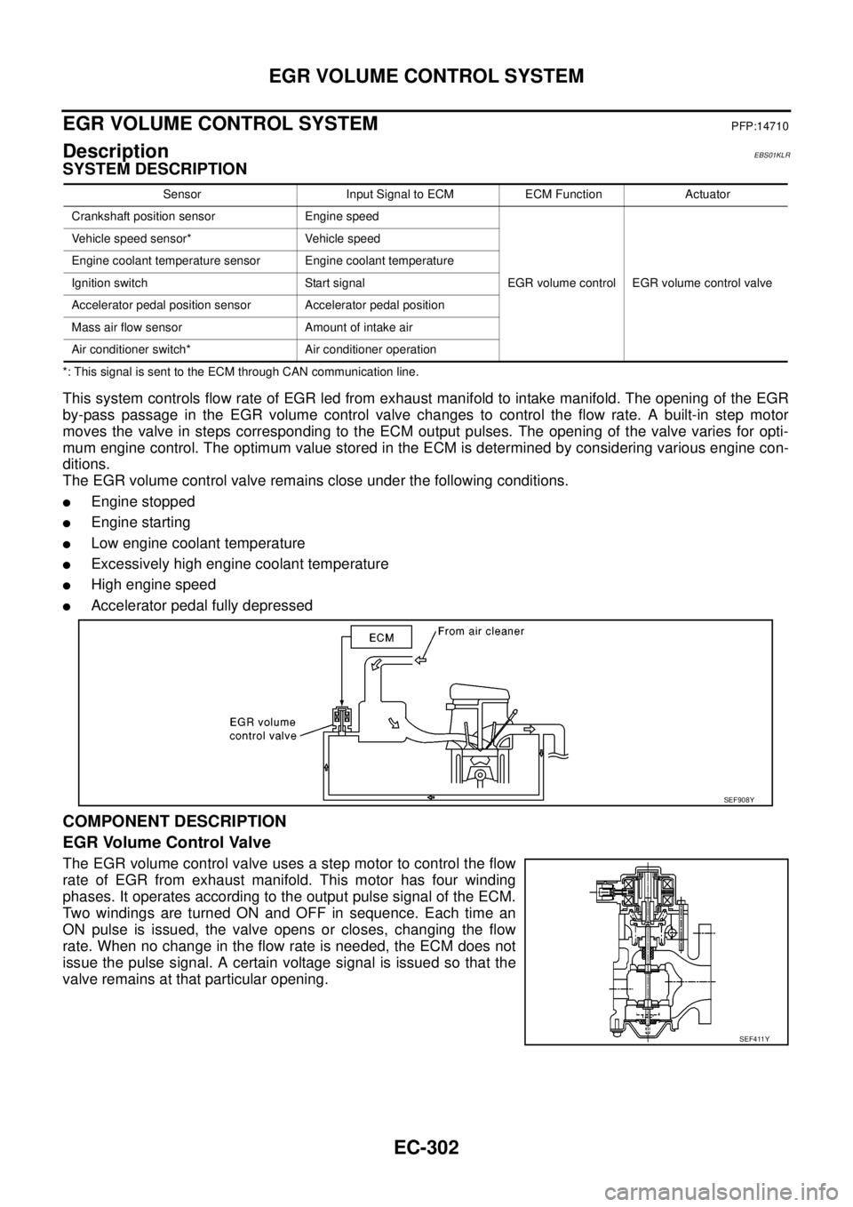
This system controls flow rate of EGR led from exhaust manifold to intake manifold. The opening of the EGR
by-pass passage in the EGR volume control valve changes to control the flow rate. A built-in step motor
moves the valve in steps corresponding to the ECM output pulses. The opening of the valve varies for opti-
mum engine control. The optimum value stored in the ECM is determined by considering various engine con-
ditions.
The EGR volume control valve remains close under the following conditions.
lEngine stopped
lEngine starting
lLow engine coolant temperature
lExcessively high engine coolant temperature
lHigh engine speed
lAccelerator pedal fully depressed
COMPONENT DESCRIPTION
EGR Volume Control Valve
The EGR volume control valve uses a step motor to control the flow
rate of EGR from exhaust manifold. This motor has four winding
phases. It operates according to the output pulse signal of the ECM.
Two windings are turned ON and OFF in sequence. Each time an
ON pulse is issued, the valve opens or closes, changing the flow
rate. When no change in the flow rate is needed, the ECM does not
issue the pulse signal. A certain voltage signal is issued so that the
valve remains at that particular opening.
Sensor Input Signal to ECM ECM Function Actuator
Crankshaft position sensor Engine speed
EGR volume control EGR volume control valve Vehicle speed sensor* Vehicle speed
Engine coolant temperature sensor Engine coolant temperature
Ignition switch Start signal
Accelerator pedal position sensor Accelerator pedal position
Mass air flow sensor Amount of intake air
Air conditioner switch* Air conditioner operation
SEF908Y
SEF411Y
Page 1346 of 3171

EI-8
SQUEAK AND RATTLE TROUBLE DIAGNOSES
3. Instrument panel to front pillar garnish
4. Instrument panel to windshield
5. Instrument panel mounting pins
6. Wiring harnesses behind the combination meter
7. A/C defroster duct and duct joint
These incidents can usually be located by tapping or moving the components to duplicate the noise or by
pressing on the components while driving to stop the noise. Most of these incidents can be repaired by apply-
ing felt cloth tape or silicone spray (in hard to reach areas). Urethane pads can be used to insulate wiring har-
ness.
CAUTION:
Do not use silicone spray to isolate a squeak or rattle. If you saturate the area with silicone, you will
not be able to recheck the repair.
CENTER CONSOLE
Components to pay attention to include:
1. Shifter assembly cover to finisher
2. A/C control unit and cluster lid C
3. Wiring harnesses behind audio and A/C control unit
The instrument panel repair and isolation procedures also apply to the center console.
DOORS
Pay attention to the:
1. Finisher and inner panel making a slapping noise
2. Inside handle escutcheon to door finisher
3. Wiring harnesses tapping
4. Door striker out of alignment causing a popping noise on starts and stops
Tapping or moving the components or pressing on them while driving to duplicate the conditions can isolate
many of these incidents.
TRUNK
Trunk noises are often caused by a loose jack or loose items put into the trunk by the owner.
In addition look for:
1. Trunk lid bumpers out of adjustment
2. Trunk lid striker out of adjustment
3. The trunk lid torsion bars knocking together
4. A loose license plate or bracket
Most of these incidents can be repaired by adjusting, securing or insulating the item(s) or component(s) caus-
ing the noise.
SUNROOF/HEADLINING
Noises in the sunroof/headlining area can often be traced to one of the following:
1. Sunroof lid, rail, linkage or seals making a rattle or light knocking noise
2. Sun visor shaft shaking in the holder
3. Front or rear windshield touching headliner and squeaking
Again, pressing on the components to stop the noise while duplicating the conditions can isolate most of these
incidents. Repairs usually consist of insulating with felt cloth tape.
OVERHEAD CONSOLE (FRONT AND REAR)
Overhead console noises are often caused by the console panel clips not being engaged correctly. Most of
these incidents are repaired by pushing up on the console at the clip locations until the clips engage.
In addition look for:
1. Loose harness or harness connectors.
2. Front console map/reading lamp lens loose.
3. Loose screws at console attachment points.