2005 NISSAN NAVARA stop start
[x] Cancel search: stop startPage 136 of 3171
AT-128
DTC P1730 A/T INTERLOCK
Judgement of A/T Interlock
ECS00FZI
When A/T Interlock is judged to be malfunctioning, the vehicle should be fixed in 2nd gear, and should be set
in a condition in which it can travel.
When one of the following fastening patterns is detected, the fail-safe function in correspondence with the indi-
vidual pattern should be performed.
NOTE:
When the vehicle is driven fixed in 2nd gear, a turbine revolution sensor malfunction is displayed, but
this is not a turbine revolution sensor malfunction.
A/T INTERLOCK COUPLING PATTERN TABLE
l:NG,X:OK
Diagnostic ProcedureECS00FZJ
1.CHECK SELF-DIAGNOSTIC RESULTS
With CONSULT-II
1. Drive vehicle.
2. Stop vehicle and turn ignition switch OFF.
3. Turn ignition switch ON. (Do not start engine.)
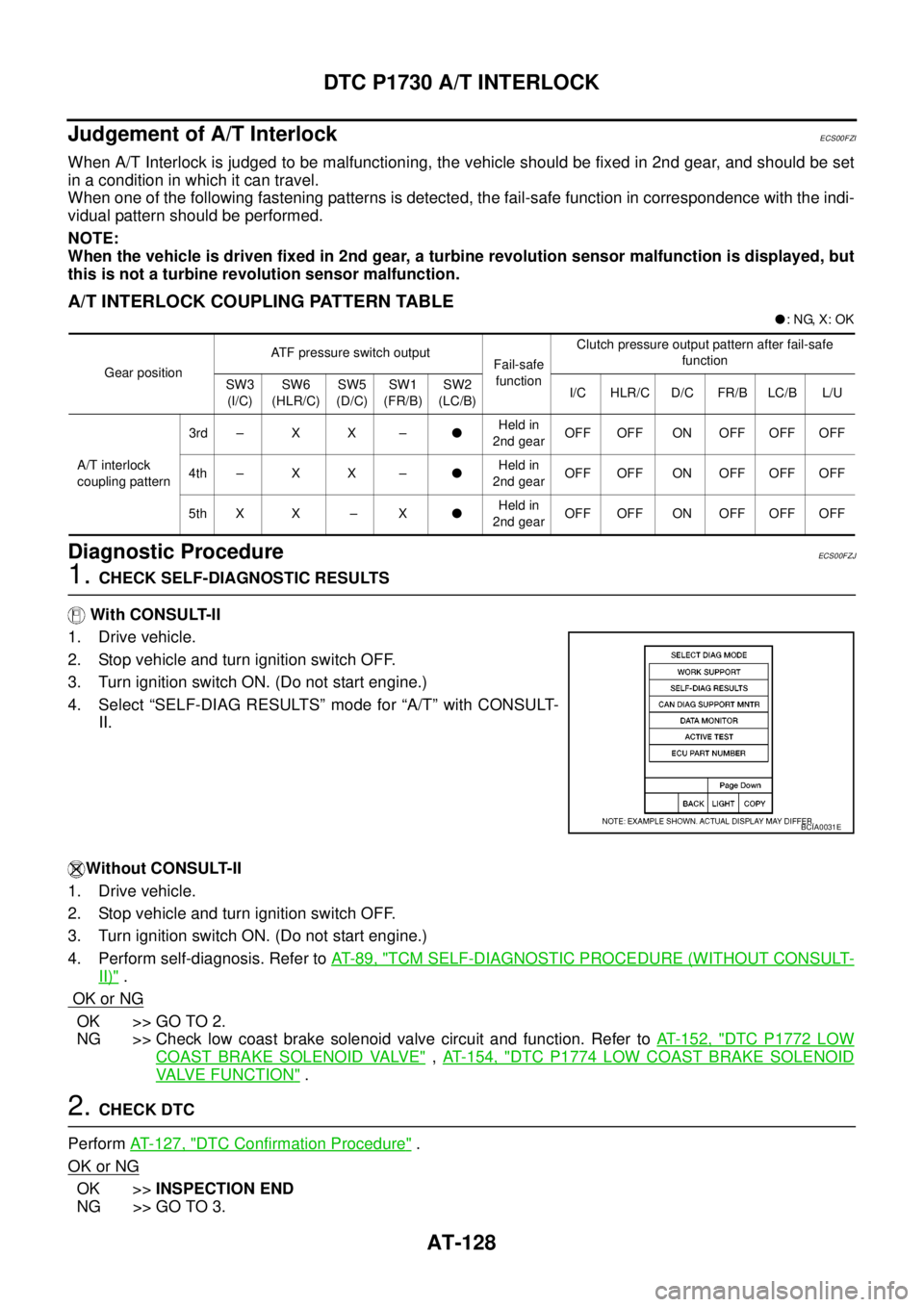
4. Select “SELF-DIAG RESULTS” mode for “A/T” with CONSULT-
II.
Without CONSULT-II
1. Drive vehicle.
2. Stop vehicle and turn ignition switch OFF.
3. Turn ignition switch ON. (Do not start engine.)
4. Perform self-diagnosis. Refer toAT-89, "
TCM SELF-DIAGNOSTIC PROCEDURE (WITHOUT CONSULT-
II)".
OK or NG
OK >> GO TO 2.
NG >> Check low coast brake solenoid valve circuit and function. Refer toAT- 1 5 2 , "
DTC P1772 LOW
COAST BRAKE SOLENOID VALVE",AT- 1 5 4 , "DTC P1774 LOW COAST BRAKE SOLENOID
VALVE FUNCTION".
2.CHECK DTC
PerformAT- 1 2 7 , "
DTC Confirmation Procedure".
OK or NG
OK >>INSPECTION END
NG >> GO TO 3.
Gear positionATF pressure switch output
Fail-safe
functionClutch pressure output pattern after fail-safe
function
SW3
(I/C)SW6
(HLR/C)SW5
(D/C)SW1
(FR/B)SW2
(LC/B)I/C HLR/C D/C FR/B LC/B L/U
A/T interlock
coupling pattern3rd – X X –lHeld in
2nd gearOFF OFF ON OFF OFF OFF
4th – X X –lHeld in
2nd gearOFF OFF ON OFF OFF OFF
5th X X – XlHeld in
2nd gearOFF OFF ON OFF OFF OFF
BCIA0031E
Page 177 of 3171

BRAKE SIGNAL CIRCUIT
AT-169
D
E
F
G
H
I
J
K
L
MA
B
AT
BRAKE SIGNAL CIRCUITPFP:25320
CONSULT-II Reference ValueECS00G26
Diagnostic ProcedureECS00G27
1.CHECK CAN COMMUNICATION LINE
Perform self-diagnosis. Refer toAT-80, "
SELF-DIAGNOSTIC RESULT MODE",AT-89, "Diagnostic Procedure
Without CONSULT-II".
Is a malfunction in the CAN communication indicated in the results?
YES >> Check CAN communication line. Refer toAT-91, "DTC U1000 CAN COMMUNICATION LINE".
NO >> GO TO 2.
2.CHECK STOP LAMP SWITCH CIRCUIT
With CONSULT-II
1. Turn ignition switch ON. (Do not start engine.)
2. Select “ECU INPUT SIGNALS” in “DATA MONITOR” mode for
“A/T” with CONSULT-II.
3. Read the ON/OFF switching action of “BRAKE SW”.
OK or NG
OK >>INSPECTION END
NG >> GO TO 3.
3.CHECK STOP LAMP SWITCH
Check continuity between stop lamp switch harness connector E109
terminals 1 and 2. Refer toAT- 1 7 4 , "
Wiring Diagram—AT—NON-
DTC".
Check stop lamp switch after adjusting brake pedal — refer to
BR-6, "
BRAKE PEDAL".
OK or NG
OK >> Check the following. If NG, repair or replace damaged
parts.
lHarness for short or open between battery and stop lamp switch.
lHarness for short or open between stop lamp switch and combination meter.
l10A fuse (No.20, located in fuse block).
NG >> Repair or replace stop lamp switch.
Item name Condition Display value
BRAKE SWDepressed brake pedal. ON
Released brake pedal. OFF
Item name Condition Display value
BRAKE SWDepressed brake pedal. ON
Released brake pedal. OFF
PCIA0070E
Condition Continuity
When brake pedal is depressed Yes
When brake pedal is released No
SCIA2144E
Page 219 of 3171
SHIFT CONTROL SYSTEM
AT-211
D
E
F
G
H
I
J
K
L
MA
B
AT
Adjustment of A/T PositionECS00G2X
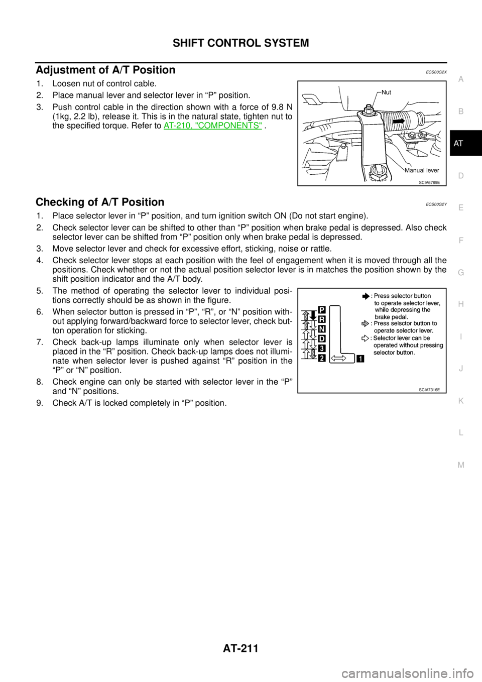
1. Loosen nut of control cable.
2. Place manual lever and selector lever in “P” position.
3. Push control cable in the direction shown with a force of 9.8 N
(1kg, 2.2 lb), release it. This is in the natural state, tighten nut to
the specified torque. Refer toAT- 2 1 0 , "
COMPONENTS".
Checking of A/T PositionECS00G2Y
1. Place selector lever in “P” position, and turn ignition switch ON (Do not start engine).
2. Check selector lever can be shifted to other than “P” position when brake pedal is depressed. Also check
selector lever can be shifted from “P” position only when brake pedal is depressed.
3. Move selector lever and check for excessive effort, sticking, noise or rattle.
4. Check selector lever stops at each position with the feel of engagement when it is moved through all the
positions. Check whether or not the actual position selector lever is in matches the position shown by the
shift position indicator and the A/T body.
5. The method of operating the selector lever to individual posi-
tions correctly should be as shown in the figure.
6. When selector button is pressed in “P”, “R”, or “N” position with-
out applying forward/backward force to selector lever, check but-
ton operation for sticking.
7. Check back-up lamps illuminate only when selector lever is
placed in the “R” position. Check back-up lamps does not illumi-
nate when selector lever is pushed against “R” position in the
“P” or “N” position.
8. Check engine can only be started with selector lever in the “P”
and “N” positions.
9. Check A/T is locked completely in “P” position.
SCIA6789E
SCIA7316E
Page 368 of 3171
ATC-34
TROUBLE DIAGNOSIS
DATA MONITOR
Operation Procedure
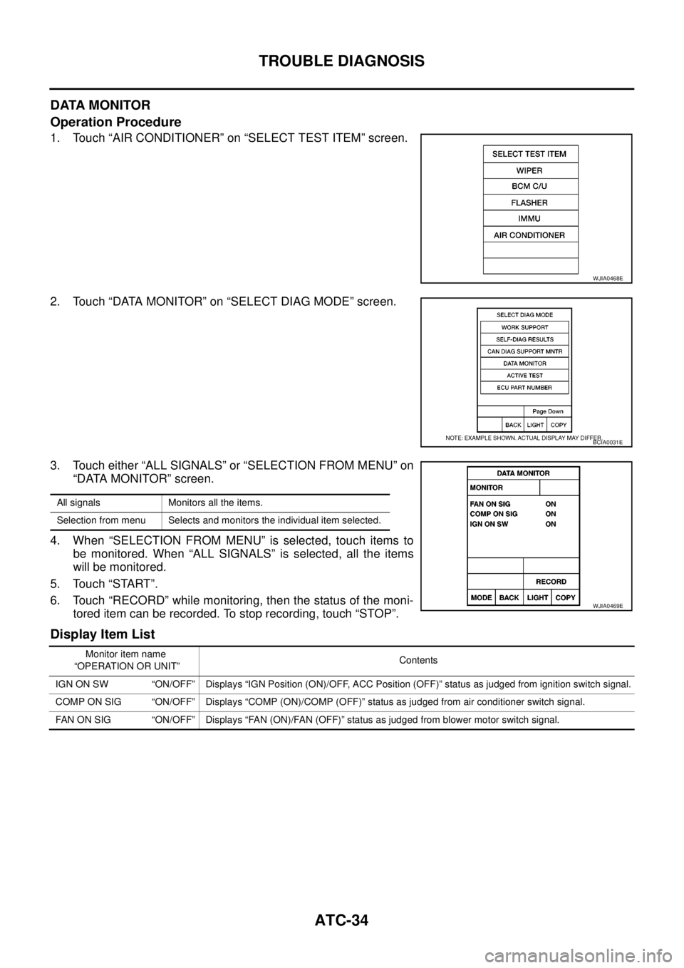
1. Touch “AIR CONDITIONER” on “SELECT TEST ITEM” screen.
2. Touch “DATA MONITOR” on “SELECT DIAG MODE” screen.
3. Touch either “ALL SIGNALS” or “SELECTION FROM MENU” on
“DATA MONITOR” screen.
4. When “SELECTION FROM MENU” is selected, touch items to
be monitored. When “ALL SIGNALS” is selected, all the items
will be monitored.
5. Touch “START”.
6. Touch “RECORD” while monitoring, then the status of the moni-
tored item can be recorded. To stop recording, touch “STOP”.
Display Item List
WJIA0468E
BCIA0031E
All signals Monitors all the items.
Selection from menu Selects and monitors the individual item selected.
WJIA0469E
Monitor item name
“OPERATION OR UNIT”Contents
IGN ON SW “ON/OFF” Displays “IGN Position (ON)/OFF, ACC Position (OFF)” status as judged from ignition switch signal.
COMP ON SIG “ON/OFF” Displays “COMP (ON)/COMP (OFF)” status as judged from air conditioner switch signal.
FAN ON SIG “ON/OFF” Displays “FAN (ON)/FAN (OFF)” status as judged from blower motor switch signal.
Page 433 of 3171
TROUBLE DIAGNOSIS
ATC-99
C
D
E
F
G
H
I
K
L
MA
B
AT C
Low-pressure Side Sometimes Becomes Negative
Low-pressure Side Becomes Negative
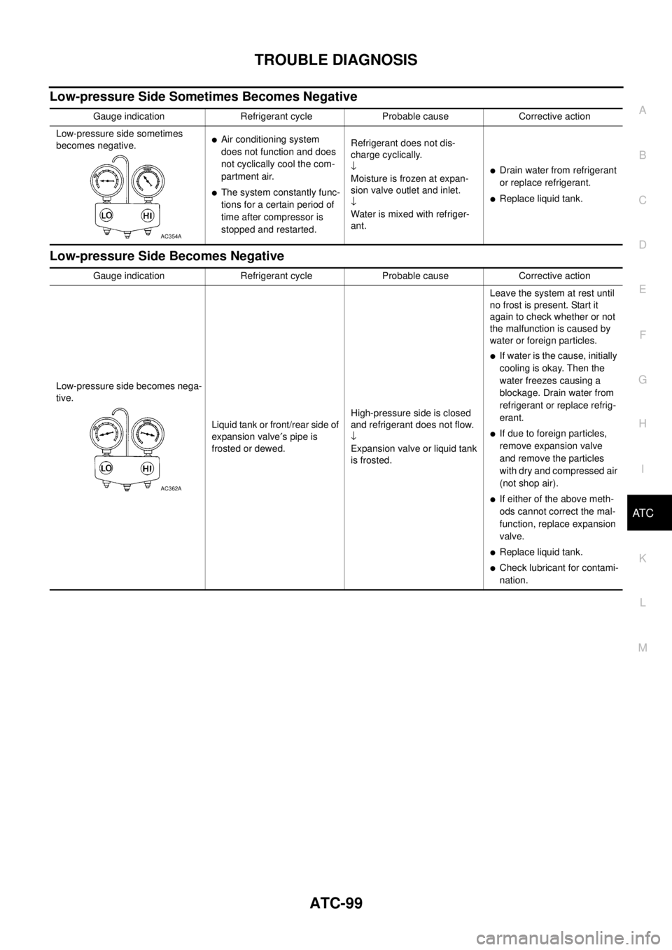
Gauge indication Refrigerant cycle Probable cause Corrective action
Low-pressure side sometimes
becomes negative.
lAir conditioning system
does not function and does
not cyclically cool the com-
partment air.
lThe system constantly func-
tions for a certain period of
time after compressor is
stopped and restarted.Refrigerant does not dis-
charge cyclically.
¯
Moisture is frozen at expan-
sion valve outlet and inlet.
¯
Water is mixed with refriger-
ant.
lDrain water from refrigerant
or replace refrigerant.
lReplace liquid tank.
AC354A
Gauge indication Refrigerant cycle Probable cause Corrective action
Low-pressure side becomes nega-
tive.
Liquid tank or front/rear side of
expansion valve¢spipeis
frosted or dewed.High-pressure side is closed
and refrigerant does not flow.
¯
Expansion valve or liquid tank
is frosted.Leave the system at rest until
no frost is present. Start it
again to check whether or not
the malfunction is caused by
water or foreign particles.
lIf water is the cause, initially
cooling is okay. Then the
water freezes causing a
blockage. Drain water from
refrigerant or replace refrig-
erant.
lIf due to foreign particles,
remove expansion valve
and remove the particles
with dry and compressed air
(not shop air).
lIf either of the above meth-
ods cannot correct the mal-
function, replace expansion
valve.
lReplace liquid tank.
lCheck lubricant for contami-
nation.
AC362A
Page 486 of 3171
ATC-152
REFRIGERANT LINES
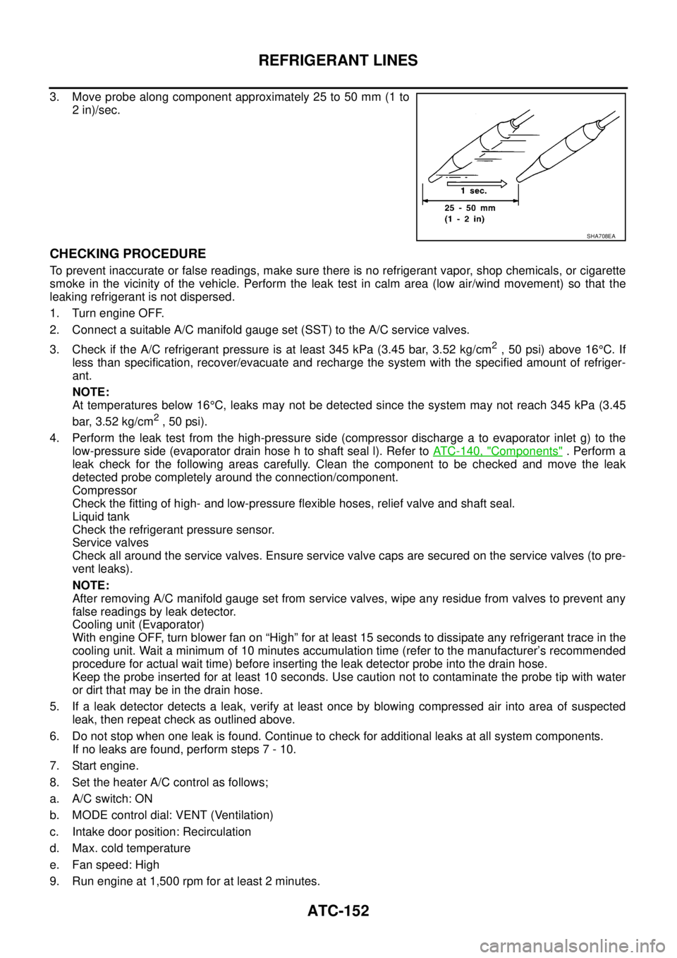
3. Move probe along component approximately 25 to 50 mm (1 to
2 in)/sec.
CHECKING PROCEDURE
To prevent inaccurate or false readings, make sure there is no refrigerant vapor, shop chemicals, or cigarette
smoke in the vicinity of the vehicle. Perform the leak test in calm area (low air/wind movement) so that the
leaking refrigerant is not dispersed.
1. Turn engine OFF.
2. Connect a suitable A/C manifold gauge set (SST) to the A/C service valves.
3. Check if the A/C refrigerant pressure is at least 345 kPa (3.45 bar, 3.52 kg/cm
2,50psi)above16°C. If
less than specification, recover/evacuate and recharge the system with the specified amount of refriger-
ant.
NOTE:
At temperatures below 16°C, leaks may not be detected since the system may not reach 345 kPa (3.45
bar, 3.52 kg/cm
2,50psi).
4. Perform the leak test from the high-pressure side (compressor discharge a to evaporator inlet g) to the
low-pressure side (evaporator drain hose h to shaft seal l). Refer toATC-140, "
Components". Perform a
leak check for the following areas carefully. Clean the component to be checked and move the leak
detected probe completely around the connection/component.
Compressor
Check the fitting of high- and low-pressure flexible hoses, relief valve and shaft seal.
Liquid tank
Check the refrigerant pressure sensor.
Service valves
Check all around the service valves. Ensure service valve caps are secured on the service valves (to pre-
vent leaks).
NOTE:
After removing A/C manifold gauge set from service valves, wipe any residue from valves to prevent any
false readings by leak detector.
Cooling unit (Evaporator)
With engine OFF, turn blower fan on “High” for at least 15 seconds to dissipate any refrigerant trace in the
cooling unit. Wait a minimum of 10 minutes accumulation time (refer to the manufacturer’s recommended
procedure for actual wait time) before inserting the leak detector probe into the drain hose.
Keep the probe inserted for at least 10 seconds. Use caution not to contaminate the probe tip with water
or dirt that may be in the drain hose.
5. If a leak detector detects a leak, verify at least once by blowing compressed air into area of suspected
leak, then repeat check as outlined above.
6. Do not stop when one leak is found. Continue to check for additional leaks at all system components.
If no leaks are found, perform steps 7 - 10.
7. Start engine.
8. Set the heater A/C control as follows;
a. A/C switch: ON
b. MODE control dial: VENT (Ventilation)
c. Intake door position: Recirculation
d. Max. cold temperature
e. Fan speed: High
9. Run engine at 1,500 rpm for at least 2 minutes.
SHA708EA
Page 538 of 3171

AV-50
DIAGNOSIS SYSTEM
SPEAKER TEST
When selecting “Speaker Test”, speaker diagnosis screen is dis-
played. When pressing “Start”, test tone sounds from the speaker. At
that time, when pressing “Start”, test tone sounds from next speaker.
Then, when pressing the “Stop”, test tone stops.
NOTE:
The frequency of test tone emitted from each speaker is as follows.
NAVIGATION
Steering Angle Adjustment
The steering angle output value detected with the gyroscope can be
adjusted.
Speed Calibration
Usually the automatic distance correction function adjusts the mal-
function in distance caused by the tires wearing down or the tire
pressure change. If prompt adjustment is necessary when the tire
chains are installed etc., perform this.Tw e e t e r : 3 k H z
Front door speaker : 300 Hz
Rear door speaker : 1 kHz
SKIB4686E
SKIB3684E
SKIB3685E
Page 559 of 3171
TROUBLE DIAGNOSIS
AV-71
C
D
E
F
G
H
I
J
L
MA
B
AV
THE CURRENT POSITION MARK SHOWS A POSITION THAT IS COMPLETELY INCORRECT.
In the following cases, the current location mark may be displayed in a location that is completely incorrect. If
so, perform position/direction correction.
lWhen location correction has not been done
–If GPS satellite reception is poor and the current location mark slips out of place, it may shift to a com-
pletely unexpected location and not return unless location correction is performed. The position will be
corrected if a GPS signal can be received.
lWhen vehicle has traveled by ferry, or when vehicle has been towed.
VehicleUse of tire chains.
The vehicle mark may deviate from
the correct road.Drivethevehicleforawhile.Ifdis-
tance still deviates, adjust it with
the distance adjustment function. (If
tire chains are removed, recover
the original value.)
Use of tires other than the specified
sizeReplace all tires with the specified
size tire.
Malfunctioning air pressure of tireAdjust all tires to the specified air
pressure.
Replace tireDrive the vehicle for a while. If the
distance is still not in the correct
location, it adjusts with the distance
adjustment function.
Driving
mannerJust after the engine is startedIf vehicle is driven off just after the
engine is started when gyroscope
(angular speed sensor) correction is
not completed, the vehicle can can
be shown in the incorrect direction
and may deviate from the correct
location.Wait for a short while before driving
after starting the engine.
Continuous driving without stoppingWhen driving long distances without
stopping, direction errors may accu-
mulate, and the current location
mark may deviate from the correct
road.Stop and adjust orientation.
Abusive drivingSpinning the wheels or engaging in
other kinds of abusive driving may
result in the system being unable
perform correct detection, and may
cause the vehicle mark to deviate
from the correct road.If after traveling about 10 km (6
MPH) the correct location has not
been restored, perform location
correction and, if necessary, direc-
tion correction.
Position cor-
rection
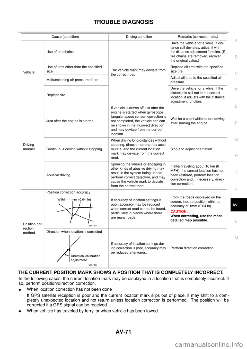
methodPosition correction accuracy
If accuracy of location settings is
poor, accuracy may be reduced
when correct road cannot be found,
particularly in places where there
are many roads.From the roads displayed on the
screen, input a position within an
accuracy of 1mm (0.04 in).
CAUTION:
When correcting, use the most
detailed map possible.
Direction when location is corrected
If accuracy of location settings dur-
ing correction is poor, accuracy may
be reduced afterwards.Perform direction correction. Cause (condition) Driving condition Remarks (correction, etc.)
SEL701V
SEL702V