2005 NISSAN NAVARA tow
[x] Cancel search: towPage 2672 of 3171
![NISSAN NAVARA 2005 Repair Workshop Manual AXLE SHAFT
RAX-9
[M226]
C
E
F
G
H
I
J
K
L
MA
B
RAX
INSPECTION AFTER REMOVAL
Axle Shaft Bearing and Cup
lCheck that the axle shaft bearing and cup roll freely and are free from noise, cracks, pitting a NISSAN NAVARA 2005 Repair Workshop Manual AXLE SHAFT
RAX-9
[M226]
C
E
F
G
H
I
J
K
L
MA
B
RAX
INSPECTION AFTER REMOVAL
Axle Shaft Bearing and Cup
lCheck that the axle shaft bearing and cup roll freely and are free from noise, cracks, pitting a](/manual-img/5/57362/w960_57362-2671.png)
AXLE SHAFT
RAX-9
[M226]
C
E
F
G
H
I
J
K
L
MA
B
RAX
INSPECTION AFTER REMOVAL
Axle Shaft Bearing and Cup
lCheck that the axle shaft bearing and cup roll freely and are free from noise, cracks, pitting and wear.
Replace if necessary.
Axle Shaft Retainer
lCheck for deformation and cracks. Replace if necessary.
Rear Axle Case
lCheck the exterior and inner machined surfaces for deformation and cracks. Replace if necessary.
INSTALLATION
Installation is in the reverse order of removal.
When installing pay attention to following points:
lInstall a new shaft guide and a new oil seal into the rear axle case.
CAUTION:
lDo not reuse the axle oil seal. The axle oil seal must be replaced every time the axle shaft assem-
bly is removed from the axle shaft housing.
lWhen installing oil seals, apply multi-purpsose grease to oil seal lips.
lInstall four new lock nuts to secure the axle shaft assembly to the rear axle case, and tighten lock nuts to
the specified torque. Refer toRAX-7, "
Removal and Installation".
lReinstall the rear brake drum. Refer toBR-31, "Removal and Installation of Drum Brake Assembly".
lAdjust the differential gear oil level.
Refer toRFD-9, "
DIFFERENTIAL GEAR OIL", for M226 without LD.
Refer toRFD-9, "
DIFFERENTIAL GEAR OIL", for M226 with LD.
lReinstall the wheel. Refer toWT-5, "Rotation".
DISASSEMBLY
1. Remove the ABS sensor rotor. Refer toBRC-39, "SENSOR ROTOR".
2. Remove the snap ring from the axle shaft using a suitable snap ring pliers.
3. Secure the axle shaft in a suitable vise as shown, and use a
brass hammer to remove studs (4) from the axle shaft retainer.
CAUTION:
lMount the axle shaft using a soft jaw vise to avoid dam-
aging the axle shaft retainer.
MDIB9051E
Page 2912 of 3171
PRECAUTIONS
SRS-3
C
D
E
F
G
I
J
K
L
MA
B
SRS
PRECAUTIONSPFP:00001
Precautions for Supplemental Restraint System (SRS) “AIR BAG” and “SEAT
BELT PRE-TENSIONER”
EHS001Y8
The Supplemental Restraint System such as “AIR BAG” and “SEAT BELT PRE-TENSIONER”, used along
with a front seat belt, helps to reduce the risk or severity of injury to the driver and front passenger for certain
types of collision. Information necessary to service the system safely is included in the SRS and SB section of
this Service Manual.
WARNING:
lTo avoid rendering the SRS inoperative, which could increase the risk of personal injury or death
in the event of a collision which would result in air bag inflation, all maintenance must be per-
formed by an authorized NISSAN/INFINITI dealer.
lImproper maintenance, including incorrect removal and installation of the SRS, can lead to per-
sonal injury caused by unintentional activation of the system. For removal of Spiral Cable and Air
Bag Module, see the SRS section.
lDo not use electrical test equipment on any circuit related to the SRS unless instructed to in this
Service Manual. SRS wiring harnesses can be identified by yellow and/or orange harnesses or
harness connectors.
Precautions for SRS “AIR BAG” and “SEAT BELT PRE-TENSIONER” ServiceEHS001Y9
lDo not use electrical test equipment to check SRS circuits unless instructed to in this Service Manual.
lBefore servicing the SRS, turn ignition switch OFF, disconnect both battery cables and wait at least 3 min-
utes.
For approximately 3 minutes after the cables are removed, it is still possible for the air bag and seat belt
pre-tensioner to deploy. Therefore, do not work on any SRS connectors or wires until at least 3 minutes
have passed.
lDiagnosis sensor unit must always be installed with their arrow marks “Ü” pointing towards the front of the
vehicle for proper operation. Also check diagnosis sensor unit for cracks, deformities or rust before instal-
lation and replace as required.
lThe spiral cable must be aligned with the neutral position since its rotations are limited. Do not attempt to
turn steering wheel or column after removal of steering gear.
lHandle air bag module carefully. Always place driver and front passenger air bag modules with the pad
side facing upward and place front side air bag module standing with stud bolt side setting bottom.
lConduct self-diagnosis to check entire SRS for proper function after replacing any components.
lAfter air bag inflates, the front instrument panel assembly should be replaced if damaged.
lAlways replace instrument panel pad following front passenger air bag deployment.
Precautions for Trouble DiagnosisEHS001YA
When you read wiring diagrams, refer to the following:
lGI-15, "How to Read Wiring Diagrams"in GI section
lPG-4, "POWER SUPPLY ROUTING CIRCUIT"in PG section
When you perform trouble diagnosis, refer to the following:
lGI-11, "How to Follow Trouble Diagnoses"in GI section
lGI-24, "How to Perform Efficient Diagnosis for an Electrical Incident"in GI section
Check for any service bulletins before servicing the vehicle.
Page 2945 of 3171
SRS-36
DRIVER AIR BAG MODULE
DRIVER AIR BAG MODULE
PFP:K8510
Removal and InstallationEHS001XS
REMOVAL
CAUTION:
lDo not attempt to repair or replace damaged direct-connect SRS component connectors. If a
driver air bag direct-connect harness connector is damaged, the spiral cable must be replaced.
lBefore servicing the SRS, turn ignition switch OFF, disconnect both battery cables and wait at
least 3 minutes.
lWhen servicing the SRS, do not work from directly in front of air bag module.
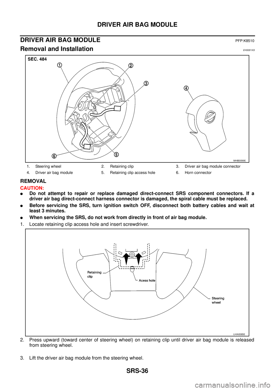
1. Locate retaining clip access hole and insert screwdriver.
2. Press upward (toward center of steering wheel) on retaining clip until driver air bag module is released
from steering wheel.
3. Lift the driver air bag module from the steering wheel.
1. Steering wheel 2. Retaining clip 3. Driver air bag module connector
4. Driver air bag module 5. Retaining clip access hole 6. Horn connector
MHIB0099E
LHIA0085E
Page 2948 of 3171
SPIRAL CABLE
SRS-39
C
D
E
F
G
I
J
K
L
MA
B
SRS
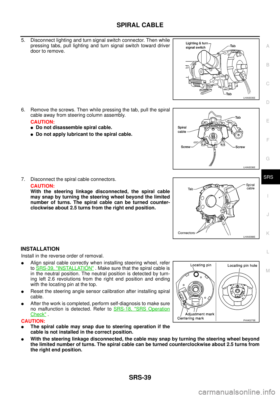
5. Disconnect lighting and turn signal switch connector. Then while
pressing tabs, pull lighting and turn signal switch toward driver
door to remove.
6. Remove the screws. Then while pressing the tab, pull the spiral
cable away from steering column assembly.
CAUTION:
lDo not disassemble spiral cable.
lDo not apply lubricant to the spiral cable.
7. Disconnect the spiral cable connectors.
CAUTION:
With the steering linkage disconnected, the spiral cable
may snap by turning the steering wheel beyond the limited
number of turns. The spiral cable can be turned counter-
clockwise about 2.5 turns from the right end position.
INSTALLATION
Install in the reverse order of removal.
lAlign spiral cable correctly when installing steering wheel, refer
toSRS-39, "
INSTALLATION". Make sure that the spiral cable is
in the neutral position. The neutral position is detected by turn-
ing left 2.6 revolutions from the right end position and ending
with the locating pin at the top.
lReset the steering angle sensor calibration after installing spiral
cable.
lAfter the work is completed, perform self-diagnosis to make sure
no malfunction is detected. Refer toSRS-18, "
SRS Operation
Check".
CAUTION:
lThe spiral cable may snap due to steering operation if the
cable is not installed in the correct position.
lWith the steering linkage disconnected, the cable may snap by turning the steering wheel beyond
the limited number of turns. The spiral cable can be turned counterclockwise about 2.5 turns from
the right end position.
LHIA0035E
LHIA0036E
LHIA0088E
PHIA0275E
Page 2957 of 3171
SRS-48
DIAGNOSIS SENSOR UNIT
DIAGNOSIS SENSOR UNIT
PFP:28556
Removal and InstallationEHS001Y0
REMOVAL
CAUTION:
lBefore servicing the SRS, turn the ignition switch off, disconnect both battery cables and wait at
least 3 minutes.
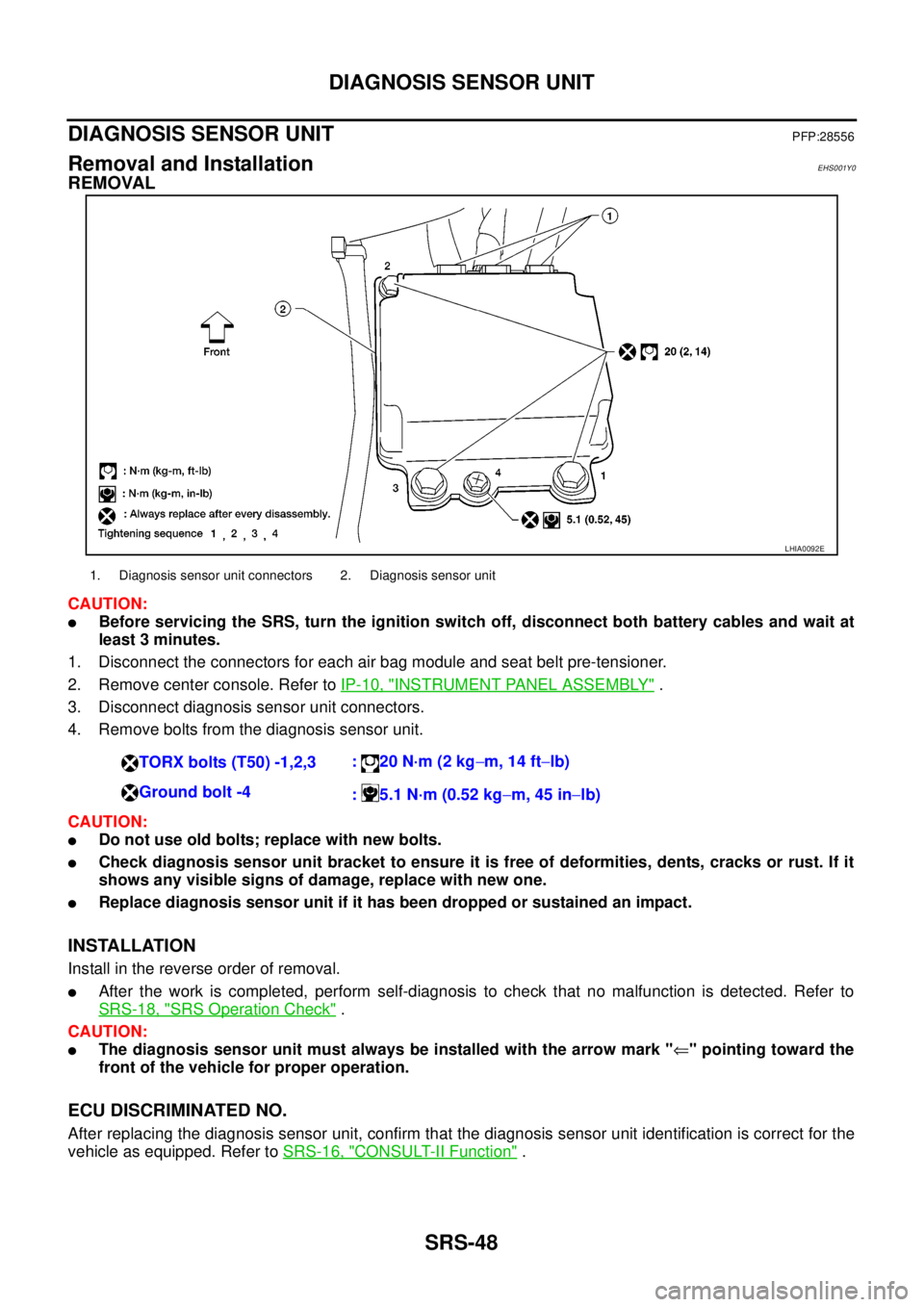
1. Disconnect the connectors for each air bag module and seat belt pre-tensioner.
2. Remove center console. Refer toIP-10, "
INSTRUMENT PANEL ASSEMBLY".
3. Disconnect diagnosis sensor unit connectors.
4. Remove bolts from the diagnosis sensor unit.
CAUTION:
lDo not use old bolts; replace with new bolts.
lCheck diagnosis sensor unit bracket to ensure it is free of deformities, dents, cracks or rust. If it
shows any visible signs of damage, replace with new one.
lReplace diagnosis sensor unit if it has been dropped or sustained an impact.
INSTALLATION
Install in the reverse order of removal.
lAfter the work is completed, perform self-diagnosis to check that no malfunction is detected. Refer to
SRS-18, "
SRS Operation Check".
CAUTION:
lThe diagnosis sensor unit must always be installed with the arrow mark "Ü" pointing toward the
front of the vehicle for proper operation.
ECU DISCRIMINATED NO.
After replacing the diagnosis sensor unit, confirm that the diagnosis sensor unit identification is correct for the
vehicle as equipped. Refer toSRS-16, "
CONSULT-II Function".
LHIA0092E
1. Diagnosis sensor unit connectors 2. Diagnosis sensor unit
TORX bolts (T50) -1,2,3:20N·m(2kg-m, 14 ft-lb)
Ground bolt -4
: 5.1 N·m (0.52 kg-m, 45 in-lb)
Page 2973 of 3171
TF-6
PRECAUTIONS
If 4WD shift indicator lamp and 4LO indicator lamp do not indicate proper pattern, install new transfer con-
trol unit and retry the above check.
PrecautionsEDS0031B
lBefore connecting or disconnecting the transfer control unit harness connector, turn ignition
switch “OFF” and disconnect the battery cables. Battery voltage is applied to transfer control unit
even if ignition switch is turned “OFF”.
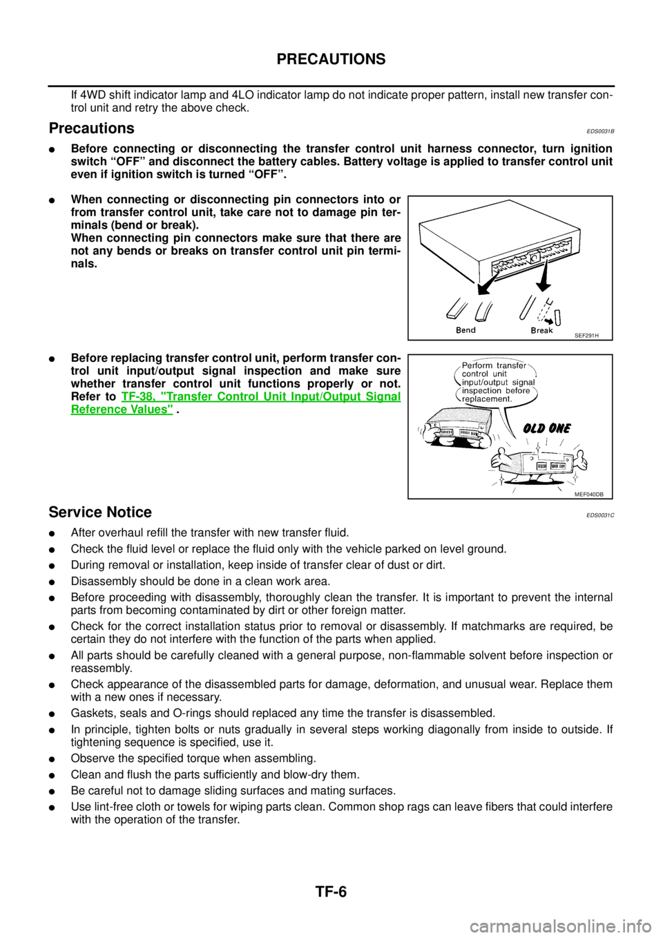
lWhen connecting or disconnecting pin connectors into or
from transfer control unit, take care not to damage pin ter-
minals (bend or break).
When connecting pin connectors make sure that there are
not any bends or breaks on transfer control unit pin termi-
nals.
lBefore replacing transfer control unit, perform transfer con-
trol unit input/output signal inspection and make sure
whether transfer control unit functions properly or not.
Refer toTF-38, "
Transfer Control Unit Input/Output Signal
Reference Values".
Service NoticeEDS0031C
lAfter overhaul refill the transfer with new transfer fluid.
lCheck the fluid level or replace the fluid only with the vehicle parked on level ground.
lDuring removal or installation, keep inside of transfer clear of dust or dirt.
lDisassemblyshouldbedoneinacleanworkarea.
lBefore proceeding with disassembly, thoroughly clean the transfer. It is important to prevent the internal
parts from becoming contaminated by dirt or other foreign matter.
lCheck for the correct installation status prior to removal or disassembly. If matchmarks are required, be
certain they do not interfere with the function of the parts when applied.
lAll parts should be carefully cleaned with a general purpose, non-flammable solvent before inspection or
reassembly.
lCheck appearance of the disassembled parts for damage, deformation, and unusual wear. Replace them
with a new ones if necessary.
lGaskets, seals and O-rings should replaced any time the transfer is disassembled.
lIn principle, tighten bolts or nuts gradually in several steps working diagonally from inside to outside. If
tightening sequence is specified, use it.
lObserve the specified torque when assembling.
lClean and flush the parts sufficiently and blow-dry them.
lBe careful not to damage sliding surfaces and mating surfaces.
lUse lint-free cloth or towels for wiping parts clean. Common shop rags can leave fibers that could interfere
with the operation of the transfer.
SEF291H
MEF040DB
Page 3108 of 3171
WHEEL
WT-3
C
D
F
G
H
I
J
K
L
MA
B
WT
WHEELPFP:40300
InspectionEES002L2
1. Check tires for wear and improper inflation.
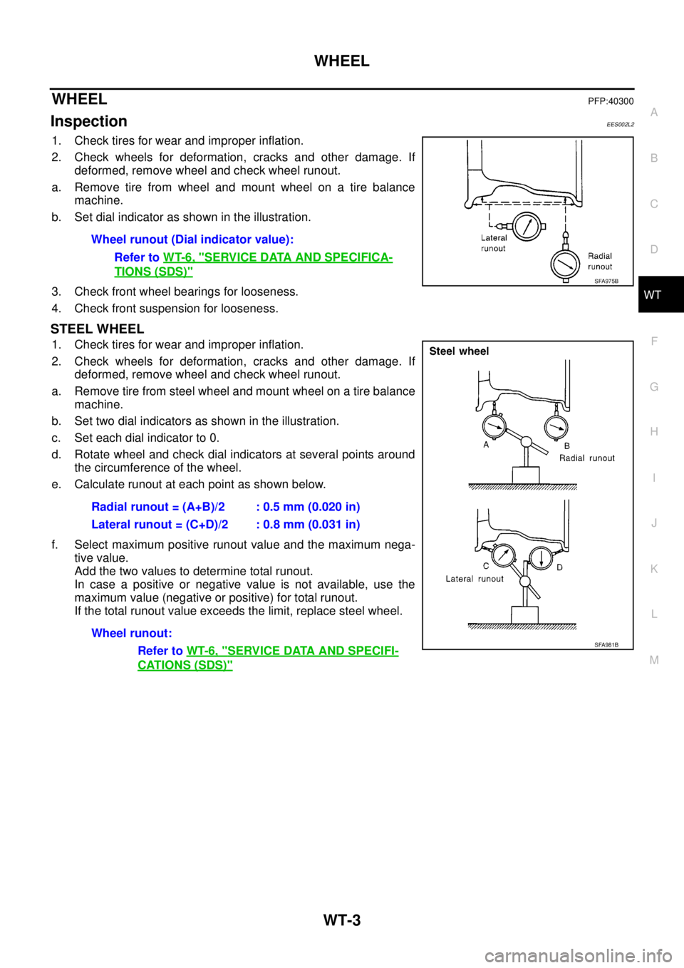
2. Check wheels for deformation, cracks and other damage. If
deformed, remove wheel and check wheel runout.
a. Remove tire from wheel and mount wheel on a tire balance
machine.
b. Set dial indicator as shown in the illustration.
3. Check front wheel bearings for looseness.
4. Check front suspension for looseness.
STEEL WHEEL
1. Check tires for wear and improper inflation.
2. Check wheels for deformation, cracks and other damage. If
deformed, remove wheel and check wheel runout.
a. Remove tire from steel wheel and mount wheel on a tire balance
machine.
b. Set two dial indicators as shown in the illustration.
c. Set each dial indicator to 0.
d. Rotate wheel and check dial indicators at several points around
the circumference of the wheel.
e. Calculate runout at each point as shown below.
f. Select maximum positive runout value and the maximum nega-
tive value.
Add the two values to determine total runout.
In case a positive or negative value is not available, use the
maximum value (negative or positive) for total runout.
If the total runout value exceeds the limit, replace steel wheel.Wheel runout (Dial indicator value):
Refer toWT-6, "
SERVICE DATA AND SPECIFICA-
TIONS (SDS)"SFA975B
Radial runout = (A+B)/2 : 0.5 mm (0.020 in)
Lateral runout = (C+D)/2 : 0.8 mm (0.031 in)
Wheel runout:
Refer toWT-6, "
SERVICE DATA AND SPECIFI-
CATIONS (SDS)"
SFA981B
Page 3118 of 3171
FRONT WIPER AND WASHER SYSTEM
WW-7
C
D
E
F
G
H
I
J
L
MA
B
WW
MIST OPERATION
When the wiper switch is temporarily placed in the mist position, wiper low speed operation cycles once and
then stops.
For additional information about wiper operation under this condition, refer toWW-5, "
LOW SPEED WIPER
OPERATION".
If the switch is held in the mist position, low speed operation continues.
FAIL-SAFE FUNCTION
The BCM includes fail-safe function to prevent malfunction of electrical components controlled by CAN com-
munications if a malfunction in CAN communications occurs.
The BCM uses CAN communications to stop output of electrical components it controls.
Until the ignition switch is turned OFF, the front wiper system remains in same status as just before fail-safe
control was initiated. (If wiper was in low speed operation just before fail-safe, it continues low speed operation
until ignition switch is turned OFF.)
When fail-safe status is initiated, the BCM remains in standby until normal signals are received.
When normal signals are received, fail-safe status is canceled.