Page 3127 of 3171

WW-16
FRONT WIPER AND WASHER SYSTEM
Terminals and Reference Values for IPDM E/R
EKS00P50
How To Proceed With Trouble DiagnosisEKS00P51
1. Confirm the trouble symptom or customer complaint.
2. Understand the operation description and function description. Refer toWW-4, "
System Description".
3. Perform preliminary inspection. Refer toWW-16, "
Preliminary Inspection".
4. According to the trouble diagnosis chart, repair or replace the cause of malfunction.
5. Does wiper function operate normally? If YES, GO TO 6. If NO, GO TO 4.
6. INSPECTION END
Preliminary InspectionEKS00P52
INSPECTION FOR POWER SUPPLY AND GROUND CIRCUIT
1.CHECK FUSE OR FUSIBLE LINK
Check for blown fuses or fusible link.
OK or NG
OK >> GO TO 2.
NG >> If fuse or fusible link is blown, be sure to eliminate cause of problem before installing new fuse or
fusible link. Refer toPG-4, "
POWER SUPPLY ROUTING CIRCUIT".
Te r m i n a l
No.Wire
colorSignal nameMeasuring condition
Reference value
Ignition
switchOperation or condition
32 GR Low speed signal ON Wiper switchOFF Approx. 0V
LO Battery voltage
35 L High speed signal ON Wiper switchOFF Approx. 0V
HI Battery voltage
38 B Ground ON — Approx. 0V
39 L CAN-H—— —
40 P CAN-L—— —
43 W Wiper auto stop signal ONWiper operating Battery voltage
Wiper stopped Approx. 0V
59 B Ground ON — Approx. 0V
Unit Power source Fuse and fusible link No.
Front washer motor Ignition ON or START 15
Front wiper main relay Battery 39
BCMIgnition ON or START 1
Battery G
Page 3138 of 3171
FRONT WIPER AND WASHER SYSTEM
WW-27
C
D
E
F
G
H
I
J
L
MA
B
WW
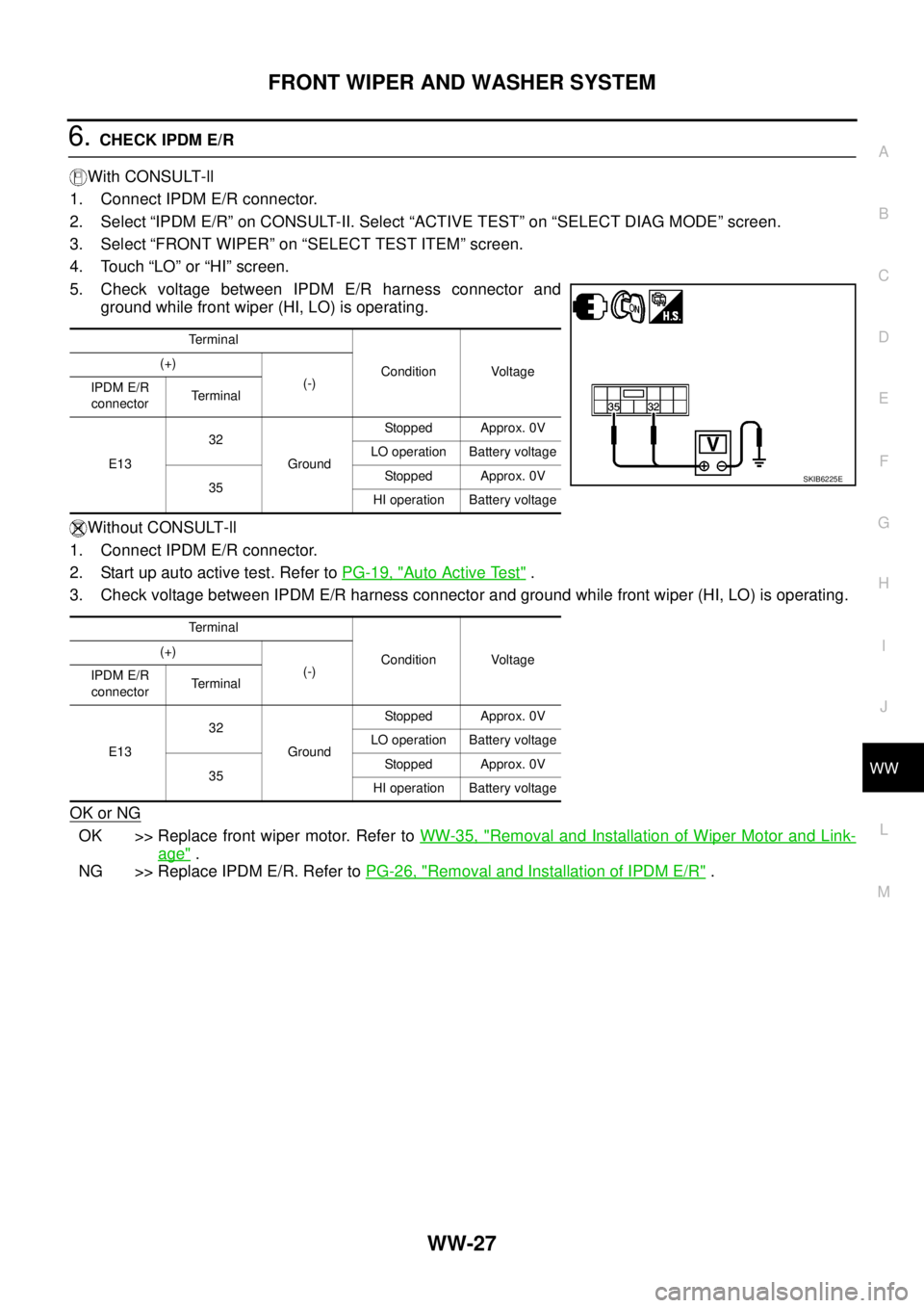
6.CHECK IPDM E/R
With CONSULT-ll
1. Connect IPDM E/R connector.
2. Select “IPDM E/R” on CONSULT-II. Select “ACTIVE TEST” on “SELECT DIAG MODE” screen.
3. Select “FRONT WIPER” on “SELECT TEST ITEM” screen.
4. Touch “LO” or “HI” screen.
5. Check voltage between IPDM E/R harness connector and
ground while front wiper (HI, LO) is operating.
Without CONSULT-ll
1. Connect IPDM E/R connector.
2. Start up auto active test. Refer toPG-19, "
Auto Active Test".
3. Check voltage between IPDM E/R harness connector and ground while front wiper (HI, LO) is operating.
OK or NG
OK >> Replace front wiper motor. Refer toWW-35, "Removal and Installation of Wiper Motor and Link-
age".
NG >> Replace IPDM E/R. Refer toPG-26, "
Removal and Installation of IPDM E/R".
Te r m i n a l
Condition Voltage (+)
(-)
IPDM E/R
connectorTerminal
E1332
GroundStopped Approx. 0V
LO operation Battery voltage
35Stopped Approx. 0V
HI operation Battery voltage
Te r m i n a l
Condition Voltage (+)
(-)
IPDM E/R
connectorTerminal
E1332
GroundStopped Approx. 0V
LO operation Battery voltage
35Stopped Approx. 0V
HI operation Battery voltage
SKIB6225E
Page 3140 of 3171
FRONT WIPER AND WASHER SYSTEM
WW-29
C
D
E
F
G
H
I
J
L
MA
B
WW
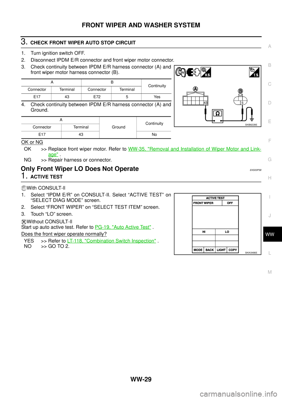
3.CHECK FRONT WIPER AUTO STOP CIRCUIT
1. Turn ignition switch OFF.
2. Disconnect IPDM E/R connector and front wiper motor connector.
3. Check continuity between IPDM E/R harness connector (A) and
front wiper motor harness connector (B).
4. Check continuity between IPDM E/R harness connector (A) and
Ground.
OK or NG
OK >> Replace front wiper motor. Refer toWW-35, "Removal and Installation of Wiper Motor and Link-
age".
NG >> Repair harness or connector.
Only Front Wiper LO Does Not OperateEKS00P58
1.ACTIVE TEST
With CONSULT-ll
1. Select “IPDM E/R” on CONSULT-II. Select “ACTIVE TEST” on
“SELECT DIAG MODE” screen.
2. Select “FRONT WIPER” on “SELECT TEST ITEM” screen.
3. Touch “LO” screen.
Without CONSULT-ll
Start up auto active test. Refer toPG-19, "
Auto Active Test".
Does the front wiper operate normally?
YES >> Refer toLT- 11 8 , "Combination Switch Inspection".
NO >> GO TO 2.
AB
Continuity
Connector Terminal Connector Terminal
E17 43 E72 5 Yes
A
GroundContinuity
Connector Terminal
E17 43 No
SKIB6228E
SKIA3486E
Page 3141 of 3171
WW-30
FRONT WIPER AND WASHER SYSTEM
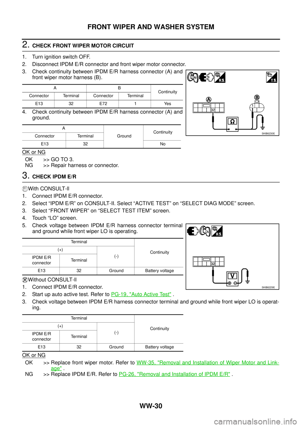
2.CHECK FRONT WIPER MOTOR CIRCUIT
1. Turn ignition switch OFF.
2. Disconnect IPDM E/R connector and front wiper motor connector.
3. Check continuity between IPDM E/R harness connector (A) and
front wiper motor harness (B).
4. Check continuity between IPDM E/R harness connector (A) and
ground.
OK or NG
OK >> GO TO 3.
NG >> Repair harness or connector.
3.CHECK IPDM E/R
With CONSULT-ll
1. Connect IPDM E/R connector.
2. Select “IPDM E/R” on CONSULT-II. Select “ACTIVE TEST” on “SELECT DIAG MODE” screen.
3. Select “FRONT WIPER” on “SELECT TEST ITEM” screen.
4. Touch “LO” screen.
5. Check voltage between IPDM E/R harness connector terminal
and ground while front wiper LO is operating.
Without CONSULT-ll
1. Connect IPDM E/R connector.
2. Startupautoactivetest.RefertoPG-19, "
Auto Active Test".
3. Check voltage between IPDM E/R harness connector terminal and ground while front wiper LO is operat-
ing.
OK or NG
OK >> Replace front wiper motor. Refer toWW-35, "Removal and Installation of Wiper Motor and Link-
age".
NG >> Replace IPDM E/R. Refer toPG-26, "
Removal and Installation of IPDM E/R".
AB
Continuity
Connector Terminal Connector Terminal
E13 32 E72 1 Yes
A
GroundContinuity
Connector Terminal
E13 32 No
SKIB6230E
Terminal
Continuity (+)
(-)
IPDM E/R
connectorTerminal
E13 32 Ground Battery voltage
Terminal
Continuity (+)
(-)
IPDM E/R
connectorTerminal
E13 32 Ground Battery voltage
SKIB6229E
Page 3143 of 3171
WW-32
FRONT WIPER AND WASHER SYSTEM
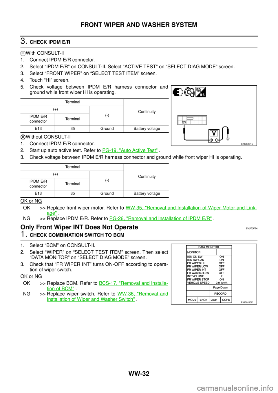
3.CHECK IPDM E/R
With CONSULT-ll
1. Connect IPDM E/R connector.
2. Select “IPDM E/R” on CONSULT-II. Select “ACTIVE TEST” on “SELECT DIAG MODE” screen.
3. Select “FRONT WIPER” on “SELECT TEST ITEM” screen.
4. Touch “HI” screen.
5. Check voltage between IPDM E/R harness connector and
ground while front wiper HI is operating.
Without CONSULT-ll
1. Connect IPDM E/R connector.
2. Startupautoactivetest.RefertoPG-19, "
Auto Active Test".
3. Check voltage between IPDM E/R harness connector and ground while front wiper HI is operating.
OK or NG
OK >> Replace front wiper motor. Refer toWW-35, "Removal and Installation of Wiper Motor and Link-
age".
NG >> Replace IPDM E/R. Refer toPG-26, "
Removal and Installation of IPDM E/R".
Only Front Wiper INT Does Not OperateEKS00P5A
1.CHECK COMBINATION SWITCH TO BCM
1. Select “BCM” on CONSULT-II.
2. Select “WIPER” on “SELECT TEST ITEM” screen. Then select
“DATA MONITOR” on “SELECT DIAG MODE” screen.
3. Check that “FR WIPER INT” turns ON-OFF according to opera-
tion of wiper switch.
OK or NG
OK >> Replace BCM. Refer toBCS-17, "Removal and Installa-
tion of BCM".
NG >> Replace wiper switch. Refer toWW-36, "
Removal and
Installation of Wiper and Washer Switch".
Terminal
Continuity (+)
(-)
IPDM E/R
connectorTerminal
E13 35 Ground Battery voltage
Terminal
Continuity (+)
(-)
IPDM E/R
connectorTerminal
E13 35 Ground Battery voltage
SKIB6231E
PKIB0110E
Page 3144 of 3171
FRONT WIPER AND WASHER SYSTEM
WW-33
C
D
E
F
G
H
I
J
L
MA
B
WW
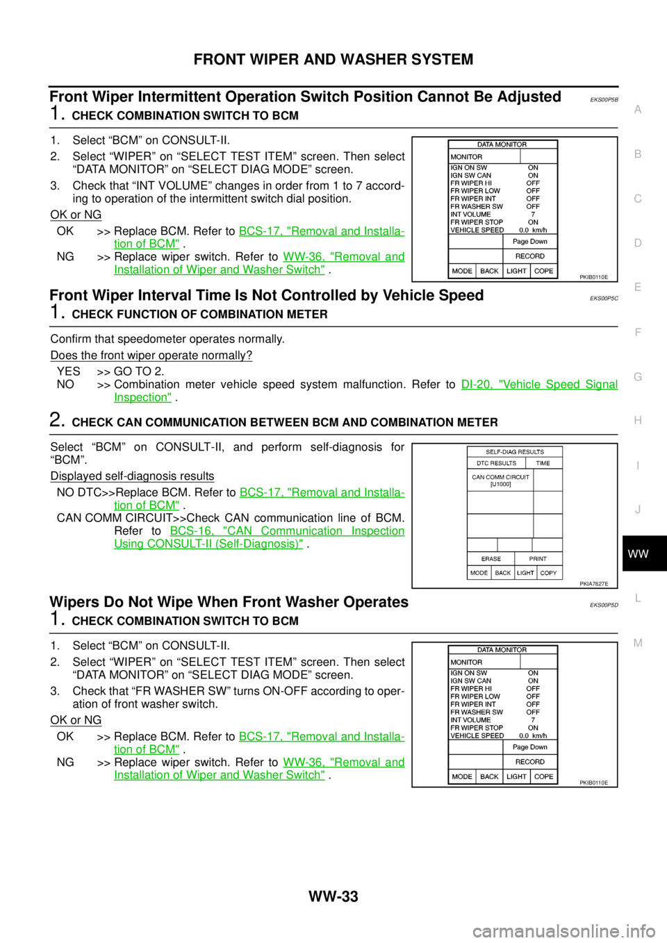
Front Wiper Intermittent Operation Switch Position Cannot Be AdjustedEKS00P5B
1.CHECK COMBINATION SWITCH TO BCM
1. Select “BCM” on CONSULT-II.
2. Select “WIPER” on “SELECT TEST ITEM” screen. Then select
“DATA MONITOR” on “SELECT DIAG MODE” screen.
3. Check that “INT VOLUME” changes in order from 1 to 7 accord-
ing to operation of the intermittent switch dial position.
OK or NG
OK >> Replace BCM. Refer toBCS-17, "Removal and Installa-
tion of BCM".
NG >> Replace wiper switch. Refer toWW-36, "
Removal and
Installation of Wiper and Washer Switch".
Front Wiper Interval Time Is Not Controlled by Vehicle SpeedEKS00P5C
1.CHECK FUNCTION OF COMBINATION METER
Confirm that speedometer operates normally.
Does the front wiper operate normally?
YES >> GO TO 2.
NO >> Combination meter vehicle speed system malfunction. Refer toDI-20, "
Vehicle Speed Signal
Inspection".
2.CHECK CAN COMMUNICATION BETWEEN BCM AND COMBINATION METER
Select “BCM” on CONSULT-II, and perform self-diagnosis for
“BCM”.
Displayed self
-diagnosis results
NO DTC>>Replace BCM. Refer toBCS-17, "Removal and Installa-
tion of BCM".
CAN COMM CIRCUIT>>Check CAN communication line of BCM.
Refer toBCS-16, "
CAN Communication Inspection
Using CONSULT-II (Self-Diagnosis)".
Wipers Do Not Wipe When Front Washer OperatesEKS00P5D
1.CHECK COMBINATION SWITCH TO BCM
1. Select “BCM” on CONSULT-II.
2. Select “WIPER” on “SELECT TEST ITEM” screen. Then select
“DATA MONITOR” on “SELECT DIAG MODE” screen.
3. Check that “FR WASHER SW” turns ON-OFF according to oper-
ation of front washer switch.
OK or NG
OK >> Replace BCM. Refer toBCS-17, "Removal and Installa-
tion of BCM".
NG >> Replace wiper switch. Refer toWW-36, "
Removal and
Installation of Wiper and Washer Switch".
PKIB0110E
PKIA7627E
PKIB0110E
Page 3149 of 3171
WW-38
FRONT WIPER AND WASHER SYSTEM
Removal and Installation of Front Washer Motor
EKS00P5K
REMOVAL
: Vehicle front
1. Remove washer tank. Refer toWW-37, "
Removal and Installation of Front Washer Tank".
2. Pull out front washer motor (1) and remove from washer tank.
INSTALLATION
Installation is the reverse order of removal.
CAUTION:
When installing front washer motor, there should be no packing twist, etc.
Removal and Installation of Washer Fluid Level SensorEKS00P5L
REMOVAL
: Vehicle front
1. Remove washer tank. Refer toWW-37, "
Removal and Installation of Front Washer Tank".
2. Pull out washer fluid level sensor (1) and remove from washer
tank in the direction of the arrow as shown.
INSTALLATION
Installation is the reverse order of removal.
CAUTION:
When installing washer fluid level sensor, there should be no packing twist, etc.
SKIB6855E
SKIB6856E
Page 3155 of 3171
WW-44
HEADLAMP WASHER
How to Proceed with Trouble Diagnosis
EKS00P6C
1. Confirm the symptoms and customer complaint.
2. Understand operation description and function description. Refer toWW-39, "
System Description".
3. Perform the Preliminary Check. Refer toWW-44, "
Preliminary Check".
4. Check symptom and repair or replace the cause of malfunction.
5. Does headlamp washer operate normally? If YES, GO TO 6. If NO, GO TO 4.
6. INSPECTION END
Preliminary CheckEKS00P6D
CHECK POWER SUPPLY AND GROUND CIRCUIT
1.CHECK FUSES OR FUSIBLE LINK
Check for blown fuses or fusible link.
Refer toWW-41, "Wiring Diagram—HLC—".
OK or NG
OK >> GO TO 2
NG >> If fuse or fusible link is blown, be sure to eliminate cause of malfunction before installing new fuse
or fusible link, Refer toPG-4, "
POWER SUPPLY ROUTING CIRCUIT".
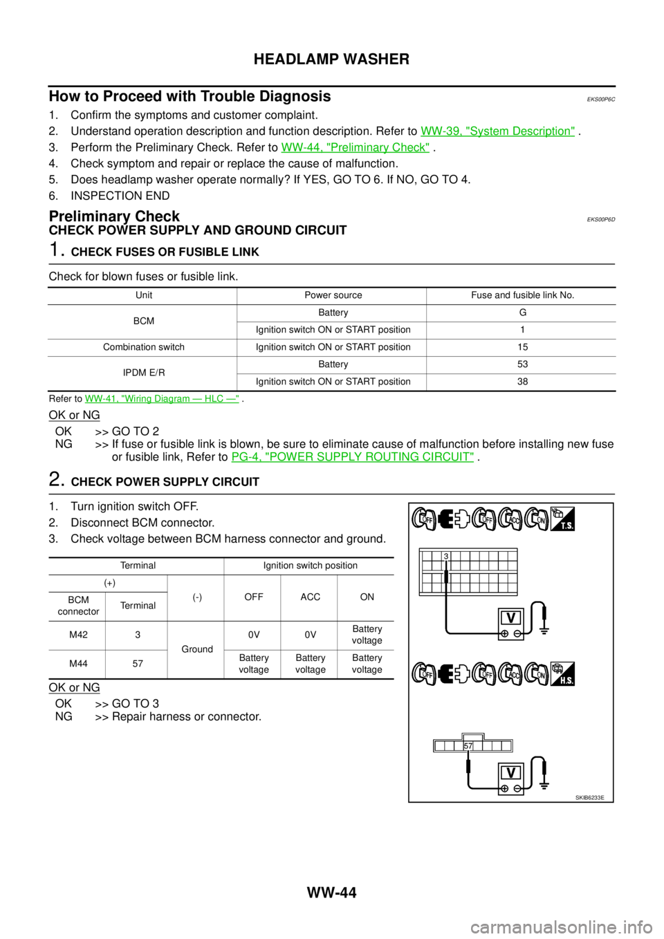
2.CHECK POWER SUPPLY CIRCUIT
1. Turn ignition switch OFF.
2. Disconnect BCM connector.
3. Check voltage between BCM harness connector and ground.
OK or NG
OK >> GO TO 3
NG >> Repair harness or connector.
Unit Power source Fuse and fusible link No.
BCMBattery G
Ignition switch ON or START position 1
Combination switch Ignition switch ON or START position 15
IPDM E/RBattery 53
Ignition switch ON or START position 38
Terminal Ignition switch position
(+)
(-) OFF ACC ON
BCM
connectorTerminal
M42 3
Ground0V 0VBattery
voltage
M44 57Battery
voltageBattery
voltageBattery
voltage
SKIB6233E