2005 NISSAN NAVARA tow
[x] Cancel search: towPage 2309 of 3171
MA-34
CHASSIS AND BODY MAINTENANCE
Changing Rear Final Drive Oil (Rear Differential Gear Oil)
ELS001IW
CAUTION:
If using the vehicle for towing, the final drive oil must be replaced as specified. Refer toMA-8, "
PERI-
ODIC MAINTENANCE".
DRAINING
1. Stop the engine.
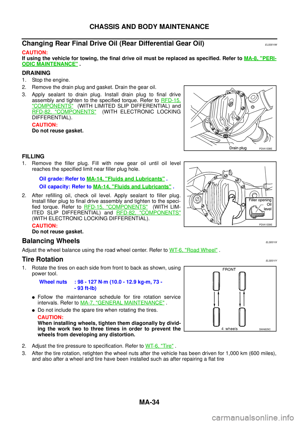
2. Remove the drain plug and gasket. Drain the gear oil.
3. Apply sealant to drain plug. Install drain plug to final drive
assembly and tighten to the specified torque. Refer toRFD-15,
"COMPONENTS"(WITH LIMITED SLIP DIFFERENTIAL) and
RFD-82, "
COMPONENTS"(WITH ELECTRONIC LOCKING
DIFFERENTIAL).
CAUTION:
Do not reuse gasket.
FILLING
1. Remove the filler plug. Fill with new gear oil until oil level
reaches the specified limit near filler plug hole.
2. After refilling oil, check oil level. Apply sealant to filler plug.
Install filler plug to final drive assembly and tighten to the speci-
fied torque. Refer toRFD-15, "
COMPONENTS"(WITH LIM-
ITED SLIP DIFFERENTIAL) andRFD-82, "
COMPONENTS"
(WITH ELECTRONIC LOCKING DIFFERENTIAL).
CAUTION:
Do not reuse gasket.
Balancing WheelsELS001IX
Adjust the wheel balance using the road wheel center. Refer toWT-6, "Road Wheel".
Tire RotationELS001IY
1. Rotate the tires on each side from front to back as shown, using
power tool.
lFollow the maintenance schedule for tire rotation service
intervals. Refer toMA-7, "
GENERAL MAINTENANCE".
lDo not include the spare tire when rotating the tires.
CAUTION:
When installing wheels, tighten them diagonally by divid-
ing the work two to three times in order to prevent the
wheels from developing any distortion.
2. Adjust the tire pressure to specification. Refer toWT-6, "
Tire".
3. After the tire rotation, retighten the wheel nuts after the vehicle has been driven for 1,000 km (600 miles),
and also after a wheel and tire have been installed such as after repairing a flat tire
PDIA1038E
Oil grade: Refer toMA-14, "Fluids and Lubricants".
Oil capacity: Refer toMA-14, "
Fluids and Lubricants".
PDIA1039E
Wheel nuts : 98 - 127 N·m (10.0 - 12.9 kg-m, 73 -
- 93 ft-lb)
SMA829C
Page 2315 of 3171
MA-40
CHASSIS AND BODY MAINTENANCE
Checking Seat Belts, Buckles, Retractors, Anchors and Adjusters
ELS001J7
Check the seat belt buckles, webbing, retractors, anchors and adjusters. Replace any seat belt assembly as
necessary. Refer toSB-11, "
Seat Belt Inspection".
lCheck the seat belt anchors for loose mounting bolts, damage, or excessive wear.
lCheck the seat belt webbing for any damage, cuts, fraying, or excessive wear.
lCheck the retractor for smooth operation.
lCheck the function of the buckles by inserting the seat belt tongue and checking for proper engagement of
the buckle and press the button on the buckle to check for proper release of the seat belt tongue.
CAUTION:
lAfter any collision, inspect all seat belt assemblies, including retractors and other attached com-
ponents, such as the guide rail set. NISSAN recommends replacing all seat belt assemblies in use
during a collision, unless they are not damaged and are inspected to confirm they are operating
properly after a minor collision.
Also inspect all seat belt assemblies that are not in use during a collision, and replace any compo-
nents if damaged or not operating properly. The seat belt pre-tensioner should be replaced even if
the seat belts are not in use during a frontal collision where the driver and passenger air bags
have been deployed.
lIf any component of the seat belt assembly is suspected of being damaged or not operating prop-
erly, do not repair the component. Replace the components as an assembly.
lIf the seat belt webbing is cut, frayed, or damaged then replace the seat belt assembly.
lNever lubricate the seat belt buckle or tongue.
lWhen replacing any seat belt assembly always use a Genuine NISSAN seat belt assembly.
Checking Body CorrosionELS001K3
Visually check body panels for collision damage (scratches, chipping, rubbing, etc.) or damage to the anti-cor-
rosion materials. In particular, check the following locations.
HEMMED PANELS
Hood front end, door lower end, trunk lid rear end, etc.
PANEL JOINT
Side sill of rear fender and center pillar, rear wheel housing of rear fender, around strut tower in engine com-
partment, etc.
PANEL EDGE
Trunk lid opening, sunroof opening, fender wheel-arch flange, fuel filler lid flange, around holes in panel, etc.
PARTS CONTACT
Waist moulding, windshield moulding, bumper, etc.
PROTECTORS
Damage or condition of mudguard, fender protector, chipping protector, etc.
ANTI-CORROSION MATERIALS
Damage or separation of anti-corrosion materials under the body.
DRAIN HOLES
Condition of drain holes at door and side sill. When repairing corroded areas, refer to the Corrosion Repair
Manual.
Page 2359 of 3171
MT-42
TRANSMISSION ASSEMBLY
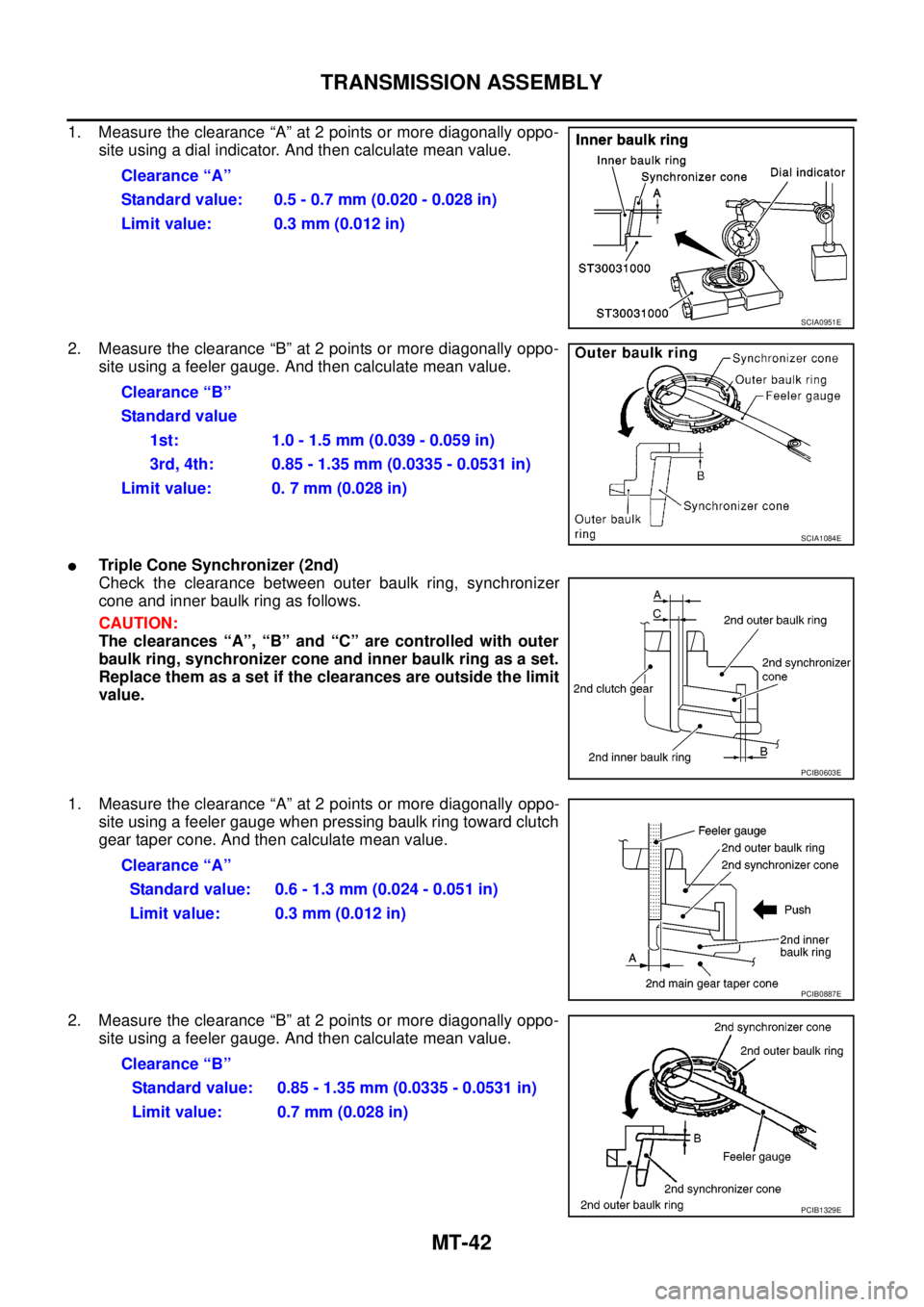
1. Measure the clearance “A” at 2 points or more diagonally oppo-
site using a dial indicator. And then calculate mean value.
2. Measure the clearance “B” at 2 points or more diagonally oppo-
site using a feeler gauge. And then calculate mean value.
lTriple Cone Synchronizer (2nd)
Check the clearance between outer baulk ring, synchronizer
cone and inner baulk ring as follows.
CAUTION:
The clearances “A”, “B” and “C” are controlled with outer
baulk ring, synchronizer cone and inner baulk ring as a set.
Replace them as a set if the clearances are outside the limit
value.
1. Measure the clearance “A” at 2 points or more diagonally oppo-
site using a feeler gauge when pressing baulk ring toward clutch
gear taper cone. And then calculate mean value.
2. Measure the clearance “B” at 2 points or more diagonally oppo-
site using a feeler gauge. And then calculate mean value.Clearance “A”
Standard value: 0.5 - 0.7 mm (0.020 - 0.028 in)
Limit value: 0.3 mm (0.012 in)
SCIA0951E
Clearance “B”
Standard value
1st: 1.0-1.5mm(0.039-0.059in)
3rd, 4th: 0.85 - 1.35 mm (0.0335 - 0.0531 in)
Limit value: 0. 7 mm (0.028 in)
SCIA1084E
PCIB0603E
Clearance “A”
Standard value: 0.6 - 1.3 mm (0.024 - 0.051 in)
Limit value: 0.3 mm (0.012 in)
PCIB0887E
Clearance “B”
Standard value: 0.85 - 1.35 mm (0.0335 - 0.0531 in)
Limit value: 0.7 mm (0.028 in)
PCIB1329E
Page 2360 of 3171
TRANSMISSION ASSEMBLY
MT-43
D
E
F
G
H
I
J
K
L
MA
B
MT
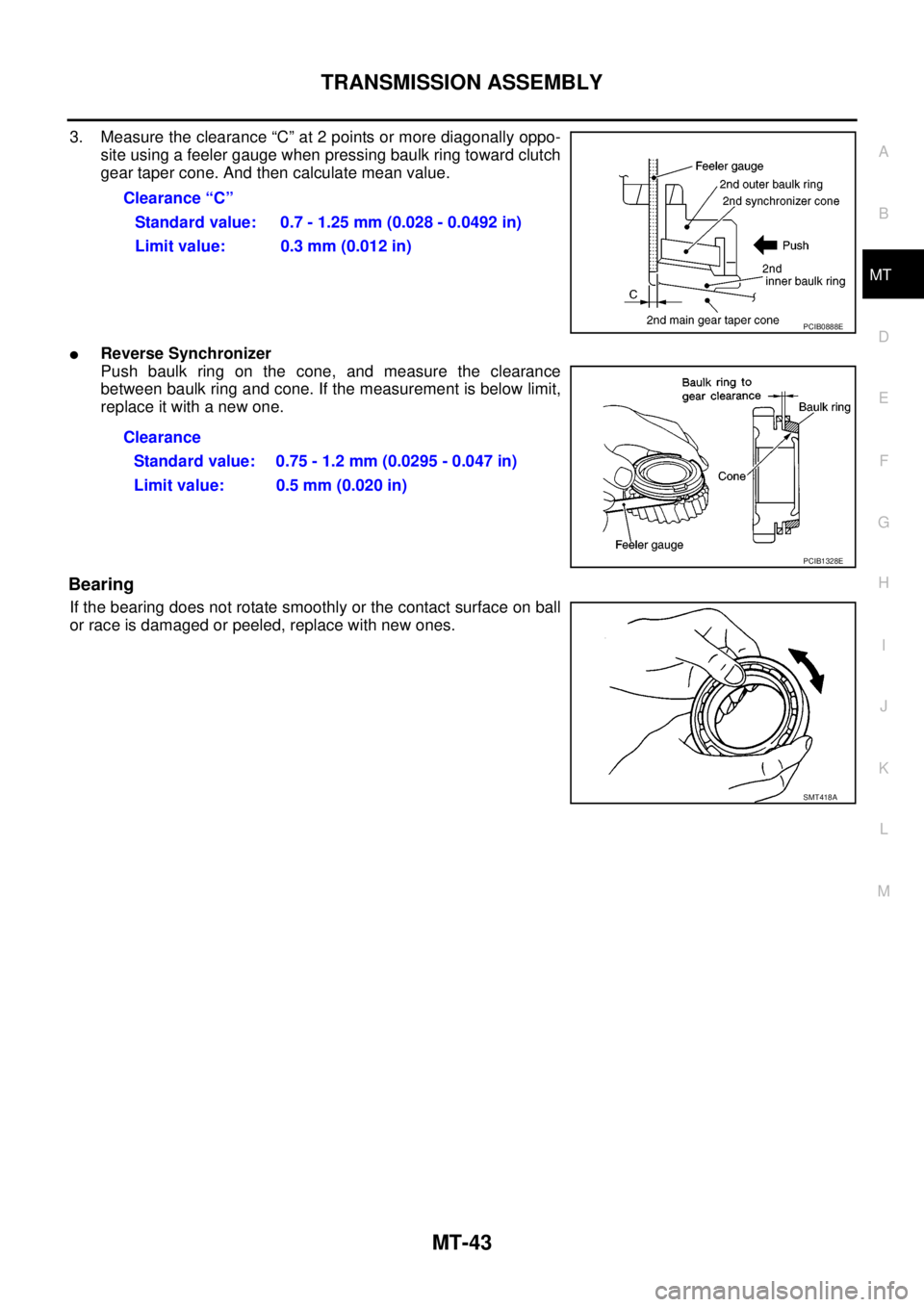
3. Measure the clearance “C” at 2 points or more diagonally oppo-
site using a feeler gauge when pressing baulk ring toward clutch
gear taper cone. And then calculate mean value.
lReverse Synchronizer
Push baulk ring on the cone, and measure the clearance
between baulk ring and cone. If the measurement is below limit,
replace it with a new one.
Bearing
If the bearing does not rotate smoothly or the contact surface on ball
or race is damaged or peeled, replace with new ones.Clearance “C”
Standard value: 0.7 - 1.25 mm (0.028 - 0.0492 in)
Limit value: 0.3 mm (0.012 in)
PCIB0888E
Clearance
Standard value: 0.75 - 1.2 mm (0.0295 - 0.047 in)
Limit value: 0.5 mm (0.020 in)
PCIB1328E
SMT418A
Page 2509 of 3171
MTC-122
REFRIGERANT LINES
Removal and Installation for Compressor
EJS005HC
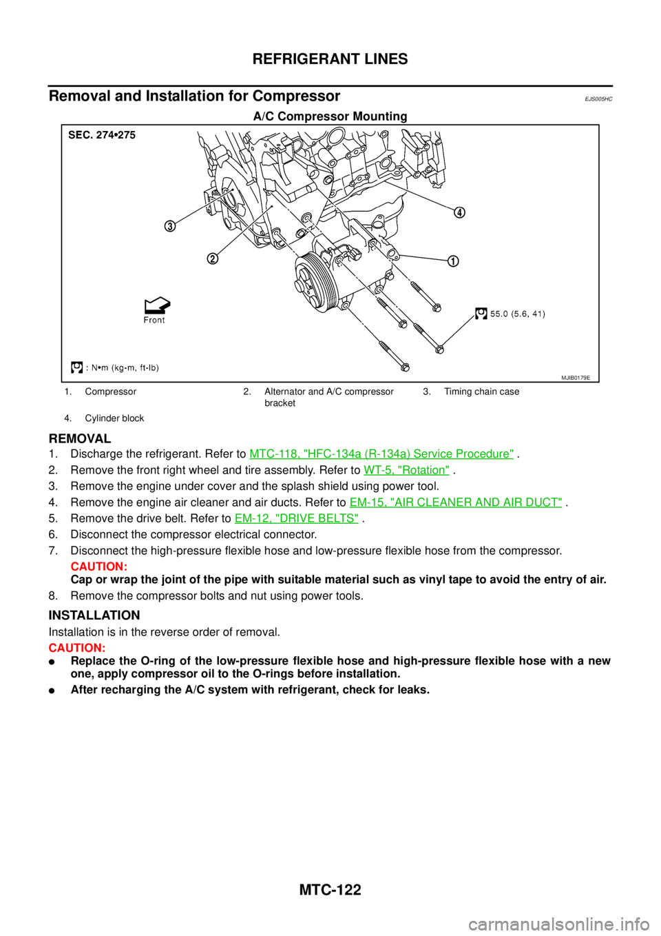
A/C Compressor Mounting
REMOVAL
1. Discharge the refrigerant. Refer toMTC-118, "HFC-134a (R-134a) Service Procedure".
2. Remove the front right wheel and tire assembly. Refer toWT-5, "
Rotation".
3. Remove the engine under cover and the splash shield using power tool.
4. Remove the engine air cleaner and air ducts. Refer toEM-15, "
AIR CLEANER AND AIR DUCT".
5. Remove the drive belt. Refer toEM-12, "
DRIVE BELTS".
6. Disconnect the compressor electrical connector.
7. Disconnect the high-pressure flexible hose and low-pressure flexible hose from the compressor.
CAUTION:
Cap or wrap the joint of the pipe with suitable material such as vinyl tape to avoid the entry of air.
8. Remove the compressor bolts and nut using power tools.
INSTALLATION
Installation is in the reverse order of removal.
CAUTION:
lReplace the O-ring of the low-pressure flexible hose and high-pressure flexible hose with a new
one, apply compressor oil to the O-rings before installation.
lAfter recharging the A/C system with refrigerant, check for leaks.
MJIB0179E
1. Compressor 2. Alternator and A/C compressor
bracket3. Timing chain case
4. Cylinder block
Page 2513 of 3171
MTC-126
REFRIGERANT LINES
BREAK-IN OPERATION
When replacing compressor clutch assembly, always conduct the break-in operation. This is done by engag-
ing and disengaging the clutch about 30 times. Break-in operation raises the level of transmitted torque.
Removal and Installation for Low-pressure Flexible HoseEJS005HE
REMOVAL
1. Remove the engine room cover using power tools.
2. Remove the engine air cleaner and air ducts. Refer toEM-15, "
AIR CLEANER AND AIR DUCT".
3. Remove the cowl top extension. Refer toEI-20, "
COWL TOP".
4. Discharge the refrigerant. Refer toMTC-118, "
HFC-134a (R-134a) Service Procedure".
CAUTION:
Cap or wrap the joint of the pipe with suitable material such as vinyl tape to avoid the entry of air.
5. Remove the low-pressure flexible hose. Refer toMTC-120, "
Components".
INSTALLATION
Installation is in the reverse order of removal.
Refer toMTC-120, "
Components".
CAUTION:
lReplace the O-ring of the low-pressure flexible hose with a new one, then apply compressor oil to
it when installing it.
lAfter charging refrigerant, check for leaks.
Removal and Installation for High-pressure Flexible HoseEJS005HF
REMOVAL
1. Remove the engine under cover.
2. Remove the engine air cleaner and air ducts. Refer toEM-15, "
AIR CLEANER AND AIR DUCT"
3. Discharge the refrigerant. Refer toMTC-118, "HFC-134a (R-134a) Service Procedure".
4. Remove the high-pressure flexible hose. Refer toMTC-120, "
Components".
CAUTION:
Cap or wrap the joint of the pipe with suitable material such as vinyl tape to avoid the entry of air.
INSTALLATION
Installation is in the reverse order of removal.
Refer toMTC-120, "
Components".
CAUTION:
lReplace the O-ring of the high-pressure flexible hose with a new one, then apply compressor oil to
it when installing it.
lAfter charging refrigerant, check for leaks.
Removal and Installation for High-pressure PipeEJS005HG
REMOVAL
1. Remove the cowl top extension. Refer toEI-20, "COWL TOP".
2. Disconnect the battery negative cable.
3. Reposition the IPDM E/R aside.
4. Remove the front right wheel and tire assembly. Refer toWT-5, "
Rotation".
5. Position aside the front floor insulator.
6. Discharge the refrigerant. Refer toMTC-118, "
HFC-134a (R-134a) Service Procedure".
7. Remove the low pressure pipe. Refer toMTC-127, "
Removal and Installation for Low-pressure Pipe".
8. Remove the high-pressure pipe. Refer toMTC-120, "
Components".
CAUTION:
Cap or wrap the joint of the pipe with suitable material such as vinyl tape to avoid the entry of air.
INSTALLATION
Installation is in the reverse order of removal.
Refer toMTC-120, "
Components".
Page 2629 of 3171
PS-2
PRECAUTIONS
PRECAUTIONS
PFP:00001
Precautions for Supplemental Restraint System (SRS) “AIR BAG” and “SEAT
BELT PRE-TENSIONER”
EGS001M0
The Supplemental Restraint System such as “AIR BAG” and “SEAT BELT PRE-TENSIONER”, used along
with a front seat belt, helps to reduce the risk or severity of injury to the driver and front passenger for certain
types of collision. Information necessary to service the system safely is included in the SRS and SB section of
this Service Manual.
WARNING:
lTo avoid rendering the SRS inoperative, which could increase the risk of personal injury or death
in the event of a collision which would result in air bag inflation, all maintenance must be per-
formed by an authorized NISSAN/INFINITI dealer.
lImproper maintenance, including incorrect removal and installation of the SRS, can lead to per-
sonal injury caused by unintentional activation of the system. For removal of Spiral Cable and Air
Bag Module, see the SRS section.
lDo not use electrical test equipment on any circuit related to the SRS unless instructed to in this
Service Manual. SRS wiring harnesses can be identified by yellow and/or orange harnesses or
harness connectors.
Precautions for Steering SystemEGS001L9
lIn case of removing steering gear assembly, make the final tightening with grounded and unloaded vehi-
cle condition, and then check wheel alignment.
lObserve the following precautions when disassembling.
–Before disassembly, thoroughly clean the outside of the unit.
–Disassembly should be done in a clean work area. It is important to prevent the internal parts from becom-
ing contaminated by dirt or other foreign matter.
–For easier and proper assembly, place disassembled parts in order on a parts rack.
–Use nylon cloth or paper towels to clean the parts; common shop rags can leave lint that might interfere
with their operation.
–Do not reuse non-reusable parts.
–Before assembling, apply the specified grease to the directed parts.
Page 2655 of 3171
PS-28
POWER STEERING OIL PUMP
Flow Control Valve Inspection
Check flow control valve and spring for damage. Replace if there are.
ASSEMBLY
NOTE:
Secureoilpumpinaviseifnecessary.
CAUTION:
Use copper plates when securing in a vise.
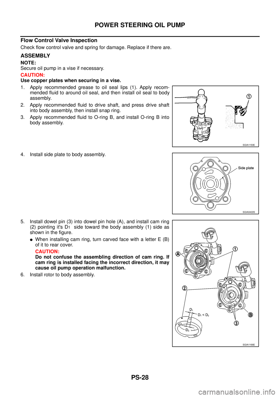
1. Apply recommended grease to oil seal lips (1). Apply recom-
mended fluid to around oil seal, and then install oil seal to body
assembly.
2. Apply recommended fluid to drive shaft, and press drive shaft
into body assembly, then install snap ring.
3. Apply recommended fluid to O-ring B, and install O-ring B into
body assembly.
4. Install side plate to body assembly.
5. Install dowel pin (3) into dowel pin hole (A), and install cam ring
(2) pointing it's D
1side toward the body assembly (1) side as
showninthefigure.
lWhen installing cam ring, turn carved face with a letter E (B)
of it to rear cover.
CAUTION:
Do not confuse the assembling direction of cam ring. If
cam ring is installed facing the incorrect direction, it may
cause oil pump operation malfunction.
6. Install rotor to body assembly.
SGIA1150E
SGIA0422E
SGIA1166E