2005 NISSAN NAVARA tow
[x] Cancel search: towPage 936 of 3171
DI-26
COMBINATION METERS
4.QUESTION 4
During driving, does the fuel gauge pointer move gradually toward EMPTY position?
YES >> Check the fuel level sensor unit. Refer toDI-27, "FUEL LEVEL SENSOR UNIT CHECK".
NO >> The float arm may interfere or bind with any of the components in the fuel tank.
DTC [U1000] CAN Communication CircuitEKS00L8X
Symptom: Displays “CAN COMM CIRC [U1000]” at the self-diagnosis result for combination meter.
1.CHECK CAN COMMUNICATION
1. Select “SELF-DIAG RESULTS” mode for “METER” with CONSULT-II.
2. Print out CONSULT-II screen.
>> Go to “LAN SYSTEM”. Refer toLAN-3, "
Precautions When Using CONSULT-II".
DTC [B2205] Vehicle Speed CircuitEKS00L8Y
Symptom: Displays “VEHICLE SPEED CIRC [B2205]” at the self-diagnosis result for combination meter.
Perform the ABS actuator and electric unit (control unit) self-diagnosis, and repair or replace malfunctioning
parts. Refer toBRC-17, "
CONSULT- II Functions".
Page 976 of 3171
DI-66
COMPASS
COMPASS
PFP:24835
System DescriptionEKS00M4Z
This unit displays earth magnetism and heading direction of vehicle.
DIRECTION DISPLAY
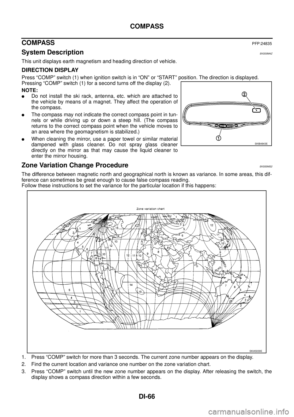
Press “COMP” switch (1) when ignition switch is in “ON” or “START” position. The direction is displayed.
Pressing “COMP” switch (1) for a second turns off the display (2).
NOTE:
lDo not install the ski rack, antenna, etc. which are attached to
the vehicle by means of a magnet. They affect the operation of
the compass.
lThe compass may not indicate the correct compass point in tun-
nels or while driving up or down a steep hill. (The compass
returns to the correct compass point when the vehicle moves to
an area where the geomagnetism is stabilized.)
lWhen cleaning the mirror, use a paper towel or similar material
dampened with glass cleaner. Do not spray glass cleaner
directly on the mirror as that may cause the liquid cleaner to
enter the mirror housing.
Zone Variation Change ProcedureEKS00MS2
The difference between magnetic north and geographical north is known as variance. In some areas, this dif-
ference can sometimes be great enough to cause false compass reading.
Follow these instructions to set the variance for the particular location if this happens:
1. Press “COMP” switch for more than 3 seconds. The current zone number appears on the display.
2. Find the current location and variance one number on the zone variation chart.
3. Press “COMP” switch until the new zone number appears on the display. After releasing the switch, the
display shows a compass direction within a few seconds.
SKIB4843E
SKIA5030E
Page 1341 of 3171
PRECAUTIONS
EI-3
C
D
E
F
G
H
J
K
L
MA
B
EI
PRECAUTIONSPFP:00001
Service NoticeEIS00DY1
lWhen removing or installing various parts, place a cloth or padding on the vehicle body to prevent
scratches.
lHandle trim, molding, instruments, grille, etc. carefully during removing or installing. Be careful not to soil
or damage them.
lApply sealing compound where necessary when installing parts.
lWhen applying sealing compound, be careful that the sealing compound does not protrude from parts.
lWhen replacing any metal parts (for example body outer panel, members, etc.), be sure to take rust pre-
vention measures.
Precautions for Supplemental Restraint System (SRS) “AIR BAG” and “SEAT
BELT PRE-TENSIONER”
EIS00DZ5
The Supplemental Restraint System such as “AIR BAG” and “SEAT BELT PRE-TENSIONER”, used along
with a front seat belt, helps to reduce the risk or severity of injury to the driver and front passenger for certain
types of collision. Information necessary to service the system safely is included in the SRS and SB section of
this Service Manual.
WARNING:
lTo avoid rendering the SRS inoperative, which could increase the risk of personal injury or death
in the event of a collision which would result in air bag inflation, all maintenance must be per-
formed by an authorized NISSAN/INFINITI dealer.
lImproper maintenance, including incorrect removal and installation of the SRS, can lead to per-
sonal injury caused by unintentional activation of the system. For removal of Spiral Cable and Air
Bag Module, see the SRS section.
lDo not use electrical test equipment on any circuit related to the SRS unless instructed to in this
Service Manual. SRS wiring harnesses can be identified by yellow and/or orange harnesses or
harness connectors.
Precautions for SRS “AIR BAG” and “SEAT BELT PRE-TENSIONER” ServiceEIS00DZ2
lDo not use electrical test equipment to check SRS circuits unless instructed to in this Service Manual.
lBefore servicing the SRS, turn ignition switch OFF, disconnect both battery cables and wait at least 3 min-
utes.
For approximately 3 minutes after the cables are removed, it is still possible for the air bag and seat belt
pre-tensioner to deploy. Therefore, do not work on any SRS connectors or wires until at least 3 minutes
have passed.
lThe air bag diagnosis sensor unit must always be installed with the arrow marks “Ü” pointing toward the
front of the vehicle for proper operation. Also check the air bag diagnosis sensor unit for cracks, deformi-
ties or rust before installation and replace as required.
lThe spiral cable must be aligned with the neutral position since its rotations are limited. Do not attempt to
turn steering wheel or column after removal of steering gear.
lHandle air bag module carefully. Always place driver and front passenger air bag modules with the pad
side facing upward and seat mounted front side air bag module standing with the stud bolt side facing
down.
lConduct self-diagnosis to check entire SRS for proper function after replacing any components.
lAfter air bag inflates, the front instrument panel assembly should be replaced if damaged.
Page 1358 of 3171
EI-20
COWL TOP
COWL TOP
PFP:66100
Removal and InstallationEIS00DYC
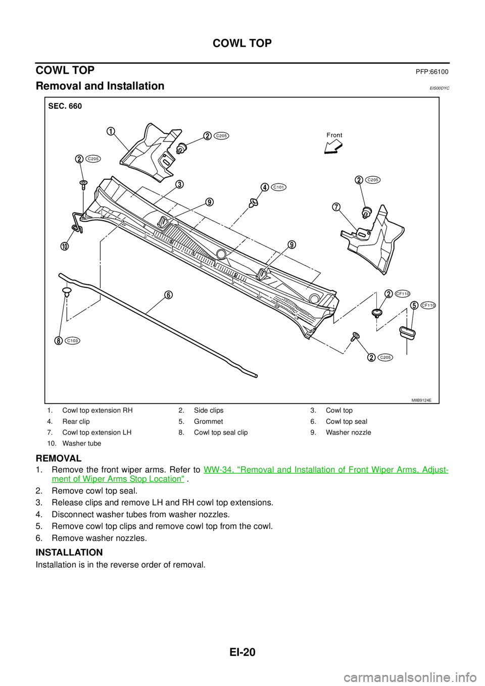
REMOVAL
1. Remove the front wiper arms. Refer toWW-34, "Removal and Installation of Front Wiper Arms, Adjust-
ment of Wiper Arms Stop Location".
2. Remove cowl top seal.
3. Release clips and remove LH and RH cowl top extensions.
4. Disconnect washer tubes from washer nozzles.
5. Remove cowl top clips and remove cowl top from the cowl.
6. Remove washer nozzles.
INSTALLATION
Installation is in the reverse order of removal.
1. Cowl top extension RH 2. Side clips 3. Cowl top
4. Rear clip 5. Grommet 6. Cowl top seal
7. Cowl top extension LH 8. Cowl top seal clip 9. Washer nozzle
10. Washer tube
MIIB9124E
Page 1433 of 3171
![NISSAN NAVARA 2005 Repair Workshop Manual FUEL PUMP
EM-51
C
D
E
F
G
H
I
J
K
L
MA
EM
8. Using the sprocket holder [SST], hold fuel pump sprocket to pre-
vent falling.
lFor sprocket holder, use KV11106060 machined as shown in
the figure, becaus NISSAN NAVARA 2005 Repair Workshop Manual FUEL PUMP
EM-51
C
D
E
F
G
H
I
J
K
L
MA
EM
8. Using the sprocket holder [SST], hold fuel pump sprocket to pre-
vent falling.
lFor sprocket holder, use KV11106060 machined as shown in
the figure, becaus](/manual-img/5/57362/w960_57362-1432.png)
FUEL PUMP
EM-51
C
D
E
F
G
H
I
J
K
L
MA
EM
8. Using the sprocket holder [SST], hold fuel pump sprocket to pre-
vent falling.
lFor sprocket holder, use KV11106060 machined as shown in
the figure, because the previous bore is not fitting.
lWhen the sprocket holder is installed, if the positioning stop-
per pin [SST] interferes, pull out the positioning stopper pin
approximately 10 mm (0.39 in), then install it.
lAfter the sprocket holder is installed temporarily, tighten the
sprocket holder after making extension bar and TORX socket
(size: E10) (commercial service tool) insert into the machined
bore.
lThe length of the sprocket holder mounting bolts should be
approximately 15 mm (0.59 in) (M6 thread length).
lMake sure that the a- and b-faces of the sprocket holder con-
tact the bottom side of the sprocket (small diameter side).
CAUTION:
Do not remove the sprocket holder [SST] until fuel pump is installed.
lAfter the sprocket holder is installed, pull out the positioning
stopper pin from fuel pump sprocket.
9. Using the extension bar and the TORX socket (size: E10) (com-
mercial service tool), remove the tightening bolts.
CAUTION:
Do not disassemble or adjust fuel pump.
10. Remove the fuel pump toward the rear of engine.
CAUTION:
For removal, be careful not to drop the seal washer into the engine.
NOTE:
The seal washer of the tightening bolts cannot be reused.
11. Remove adjusting shim.
12. Attach a suitable tool in the M8 bolt hole on coupling.
SBIA0217E
PBIC2534E
MBIA0075E
PBIC2405E
Page 1481 of 3171

CYLINDER HEAD
EM-99
C
D
E
F
G
H
I
J
K
L
MA
EM
ComponentsEBS01EKD
Disassembly and AssemblyEBS01E6C
DISASSEMBLY
1. Remove adjusting shims and valve lifters.
lCheck the installation positions, and keep them to avoid being confused.
2. Remove valve collet.
lUsing the valve spring compressor [SST], compress valve
spring. Using magnet hand, remove valve collets.
3. Remove valve spring retainers and valve springs.
4. Remove valves as pressing valve stems toward combustion chamber.
lBefore removing valve, check the valve guide clearance. Refer toEM-101, "Valve Guide Clearance".
1. Adjusting shim 2. Valve lifter 3. Valve collet
4. Valve spring retainer 5. Valve spring 6. Valve oil seal
7. Valve spring seat 8. Valve guide 9. Cylinder head
10. Valve seat 11. Valve (Exhaust) 12. Valve (Intake)
PBIC2328E
PBIC2388E
Page 1498 of 3171
EM-116
CYLINDER BLOCK
7. Install main bearing caps.
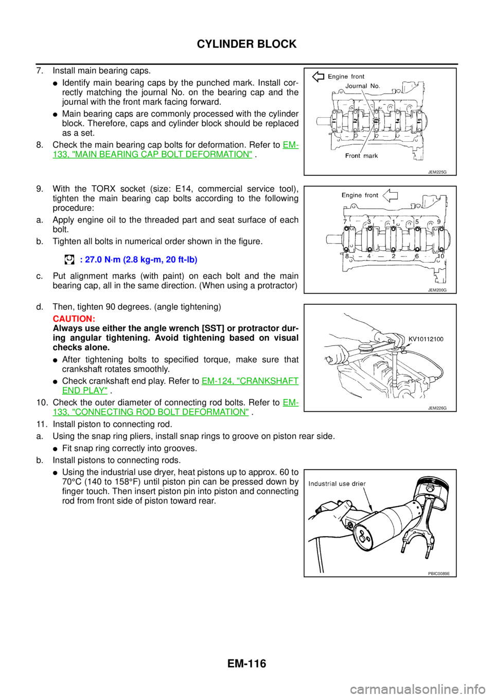
lIdentify main bearing caps by the punched mark. Install cor-
rectly matching the journal No. on the bearing cap and the
journal with the front mark facing forward.
lMain bearing caps are commonly processed with the cylinder
block. Therefore, caps and cylinder block should be replaced
as a set.
8. Check the main bearing cap bolts for deformation. Refer toEM-
133, "MAIN BEARING CAP BOLT DEFORMATION".
9. With the TORX socket (size: E14, commercial service tool),
tighten the main bearing cap bolts according to the following
procedure:
a. Apply engine oil to the threaded part and seat surface of each
bolt.
b. Tighten all bolts in numerical order shown in the figure.
c. Put alignment marks (with paint) on each bolt and the main
bearing cap, all in the same direction. (When using a protractor)
d. Then, tighten 90 degrees. (angle tightening)
CAUTION:
Always use either the angle wrench [SST] or protractor dur-
ing angular tightening. Avoid tightening based on visual
checks alone.
lAfter tightening bolts to specified torque, make sure that
crankshaft rotates smoothly.
lCheck crankshaft end play. Refer toEM-124, "CRANKSHAFT
END PLAY".
10. Check the outer diameter of connecting rod bolts. Refer toEM-
133, "CONNECTING ROD BOLT DEFORMATION".
11. Install piston to connecting rod.
a. Using the snap ring pliers, install snap rings to groove on piston rear side.
lFit snap ring correctly into grooves.
b. Install pistons to connecting rods.
lUsing the industrial use dryer, heat pistons up to approx. 60 to
70°C(140to158°F) until piston pin can be pressed down by
finger touch. Then insert piston pin into piston and connecting
rod from front side of piston toward rear.
JEM225G
: 27.0 N·m (2.8 kg-m, 20 ft-lb)
JEM200G
JEM226G
PBIC0089E
Page 1499 of 3171
CYLINDER BLOCK
EM-117
C
D
E
F
G
H
I
J
K
L
MA
EM
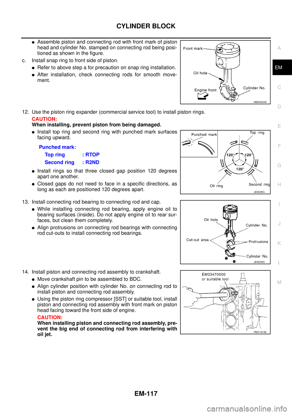
lAssemble piston and connecting rod with front mark of piston
head and cylinder No. stamped on connecting rod being posi-
tioned as shown in the figure.
c. Install snap ring to front side of piston.
lRefer to above step a for precaution on snap ring installation.
lAfter installation, check connecting rods for smooth move-
ment.
12. Use the piston ring expander (commercial service tool) to install piston rings.
CAUTION:
When installing, prevent piston from being damaged.
lInstall top ring and second ring with punched mark surfaces
facing upward.
lInstall rings so that three closed gap position 120 degrees
apart one another.
lClosed gaps do not need to face in a specific directions, as
long as each are positioned 120 degrees apart.
13. Install connecting rod bearing to connecting rod and cap.
lWhile installing connecting rod bearing, apply engine oil to
bearing surfaces (inside). Do not apply engine oil to rear sur-
faces, but clean them completely.
lAlign protrusions on connecting rod bearings with connecting
rod cut-outs to install connecting rod bearings.
14. Install piston and connecting rod assembly to crankshaft.
lMove crankshaft pin to be assembled to BDC.
lAlign cylinder position with cylinder No. on connecting rod to
install piston and connecting rod assembly.
lUsing the piston ring compressor [SST] or suitable tool, install
piston and connecting rod assembly with front mark on piston
head facing toward the front side of engine.
CAUTION:
When installing piston and connecting rod assembly, pre-
vent the big end of connecting rod from interfering with
oil jet.
MBIA0024E
Punched mark:
To p r i n g : R TO P
Second ring : R2ND
JEM228G
JEM229G
PBIC1619E