Page 560 of 3171

AV-72
TROUBLE DIAGNOSIS
–Because calculation of the current location cannot be done when traveling with the ignition OFF, for exam-
ple when traveling by ferry or when being towed, the location before travel is displayed. If the precise loca-
tioncanbedetectedwithGPS,thelocationwillbecorrected.
THE CURRENT POSITION MARK JUMPS.
In the following cases, the current location mark may appear to jump as a result of automatic correction of the
current location.
lWhen map matching has been done
–If current location and the current location mark are different when map matching is done, the current
location mark may seem to jump. At this time, the location may be “corrected” to the incorrect road or to a
location which is not on a road.
lWhen GPS location correction has been done
–If current location and the current location mark are different when location is corrected using GPS mea-
surements, the current location mark may seem to jump. At this time, the location may be “corrected” to a
location which is not on a road.
THE CURRENT LOCATION MARK IS IN A RIVER OR THE SEA.
The navigation system moves the current location mark with no distinction between land and rivers or sea. If
the location mark is somehow out of place, it may appear that the vehicle is driving in a river or the sea.
CURRENT LOCATION MARK ROTATES WITHOUT OPERATION
If the ignition switch is turned ON with the turntable rotating, the rotating condition is recorded as the stop con-
dition. Therefore, the current location mark might rotate when actually stopping.
WHEN DRIVING ON THE SAME ROAD, SOMETIMES THE CURRENT LOCATION MARK IS IN
THE CORRECT PLACE AND SOMETIMES IT IS IN THE INCORRECT PLACE.
The conditions of the GPS antenna (GPS data) and gyroscope (angular speed sensor) change gradually.
Depending on the road traveled and operation of the steering wheel, the location detection results will be dif-
ferent. Therefore, even on a road on which the location has never been incorrect, conditions may cause the
vehicle mark to deviate.
LOCATION CORRECTION BY MAP MATCHING IS SLOW.
lThe map matching function needs to refer to the data of the surrounding area. It is necessary to drive
some distance for the function to work.
lBecause of the way map matching operates, when there are many roads running in similar directions in
the surrounding area a matching determination may be impossible. The location will remain uncorrected
until some special feature is found.
ALTHOUGH THE GPS RECEIVING DISPLAY IS GREEN, THE VEHICLE MARK DOES NOT
RETURN TO THE CORRECT LOCATION.
lGPS accuracy has a malfunction range of about 10 m. In some cases the current location mark may not
be on the correct street, even when GPS location correction is done.
lThe navigation system compares the results of GPS location detection with the results from map-match-
ing location detection. The one that is determined to have higher accuracy is used.
lPosition correction by GPS is not available while the vehicle is stopped.
THE NAME OF THE CURRENT PLACE IS NOT DISPLAYED.
The current place name might not be displayed when there is no name of place information in the map screen.
THE DISPLAY IS DIFFERENT BETWEEN BIRDVIEW®AND (FLAT) MAP DISPLAY.
The following is different at birdview®.
lThe current place name displays names that are primarily in the direction of vehicle travel.
lThe amount of time before the vehicle travel or turn angle is updated on the screen is longer than for the
(flat) map display.
lThe conditions for display of place names, roads, and other data are different for nearby areas and for
more distant areas.
lSome trimming of the character data is done to prevent the display from becoming too complex. In some
cases and in some locations, the display contents may differ.
lThe same place name, street name, etc. may be displayed multiple times.
Page 711 of 3171
FRONT DOOR LOCK
BL-127
C
D
E
F
G
H
J
K
L
MA
B
BL
7. Remove the door side grommet, and remove the outside handle
bracket bolt from grommet hole.
CAUTION:
Do not forcibly remove the TORX bolt.
8. Reach to separate the key cylinder rod and outside handle rod connection (on the handle). If no door key
cylinder is found, go to 10.
9. Remove the door side grommet, and door key cylinder is
decomposed into (1) and (2).
10. While pulling the outside handle, remove the door key cylinder
assembly in order of (1) and (2).
11. While pulling outside handle, slide toward rear of vehicle to
remove the outside handle in order of (1) and (2).: 6.1 N·m (0.63 kg-m, 54.0 in-lb)
MIIB0630E
MIIB0664E
MIIB0631E
MIIB0632E
Page 712 of 3171
BL-128
FRONT DOOR LOCK
12. Remove the front gasket and rear gasket.
13. Remove the TORX bolts (T30), remove the door lock assembly.
14. While pulling outside handle bracket, slide toward rear of vehicle
to remove the outside handle bracket and door lock assembly.
15. Disconnect the door lock actuator connector.
16. Reach in to separate the key cylinder rod and outside handle
cable connection.
MIIB0559E
: 5.8 N·m (0.60 kg-m, 51.4 in-lb)
MIIB0633E
MIIB0634E
PIIB2878J
Page 717 of 3171
REAR DOOR LOCK
BL-133
C
D
E
F
G
H
J
K
L
MA
B
BL
7. Remove the door side grommet, and remove the outside handle
bracket bolt from grommet hole.
CAUTION:
Do not forcibly remove the TORX bolt.
8. While pulling the outside handle, remove outside handle
escutcheon in order of (1) and (2).
9. While pulling outside handle, slide toward rear of vehicle to
remove the outside handle in order of (1) and (2).
10. Remove the front gasket and rear gasket.
11. Remove the TORX bolts (T30), remove the door lock assembly.: 6.1 N·m (0.63 kg-m, 54.0 in-lb)
MIIB0630E
LIIA1971E
MIIB0632E
MIIB0559E
: 5.8 N·m (0.60 kg-m, 51.4 in-lb)
MIIB0633E
Page 718 of 3171
BL-134
REAR DOOR LOCK
12. While pulling outside handle bracket, slide toward rear of vehicle
to remove the outside handle bracket and door lock assembly.
13. Disconnect the door lock actuator connector.
14. Reach in to separate the key cylinder rod and outside handle
cable connection.
INSTALLATION
Note the following, and install in the reverse order of removal.
CAUTION:
lTo install each rod, be sure to rotate the rod holder until a click is felt.
lPlace the outside handle bracket cable on the rear of door lock assembly before installing.
MIIB0634E
PIIB2878J
Page 753 of 3171

THEFT WARNING SYSTEM
BL-169
C
D
E
F
G
H
J
K
L
MA
B
BL
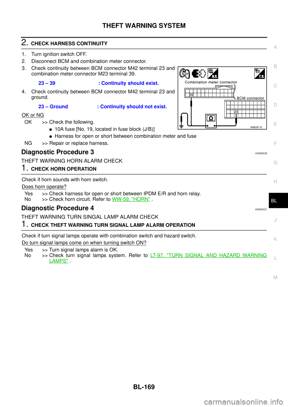
2.CHECK HARNESS CONTINUITY
1. Turn ignition switch OFF.
2. Disconnect BCM and combination meter connector.
3. Check continuity between BCM connector M42 terminal 23 and
combination meter connector M23 terminal 39.
4. Check continuity between BCM connector M42 terminal 23 and
ground.
OK or NG
OK >> Check the following.
l10Afuse[No.19,locatedinfuseblock(J/B)]
lHarness for open or short between combination meter and fuse
NG >> Repair or replace harness.
Diagnostic Procedure 3EIS00DCB
THEFT WARNING HORN ALARM CHECK
1.CHECK HORN OPERATION
Check if horn sounds with horn switch.
Does horn operate?
Yes >> Check harness for open or short between IPDM E/R and horn relay.
No >> Check horn circuit. Refer toWW-59, "
HORN".
Diagnostic Procedure 4EIS00DCC
THEFT WARNING TURN SINGAL LAMP ALARM CHECK
1.CHECK THEFT WARNING TURN SIGNAL LAMP ALARM OPERATION
Check if turn signal lamps operate with combination switch and hazard switch.
DoturnsignallampscomeonwhenturningswitchON?
Yes >> Turn signal lamps alarm is OK.
No >> Check turn signal lamps system. Refer toLT- 9 7 , "
TURN SIGNAL AND HAZARD WARNING
LAMPS". 23 – 39 : Continuity should exist.
23 – Ground : Continuity should not exist.
MIIB0871E
Page 903 of 3171

COOLING FAN
CO-19
C
D
E
F
G
H
I
J
K
L
MA
CO
COOLING FANPFP:21140
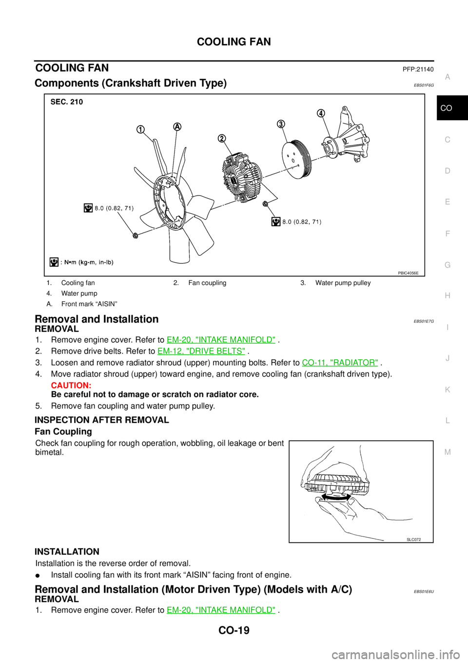
Components (Crankshaft Driven Type)EBS01F6G
Removal and InstallationEBS01E7G
REMOVAL
1. Remove engine cover. Refer toEM-20, "INTAKE MANIFOLD".
2. Remove drive belts. Refer toEM-12, "
DRIVE BELTS".
3. Loosen and remove radiator shroud (upper) mounting bolts. Refer toCO-11, "
RADIATOR".
4. Move radiator shroud (upper) toward engine, and remove cooling fan (crankshaft driven type).
CAUTION:
Be careful not to damage or scratch on radiator core.
5. Remove fan coupling and water pump pulley.
INSPECTION AFTER REMOVAL
Fan Coupling
Check fan coupling for rough operation, wobbling, oil leakage or bent
bimetal.
INSTALLATION
Installation is the reverse order of removal.
lInstall cooling fan with its front mark “AISIN” facing front of engine.
Removal and Installation (Motor Driven Type) (Models with A/C)EBS01E6U
REMOVAL
1. Remove engine cover. Refer toEM-20, "INTAKE MANIFOLD".
1. Cooling fan 2. Fan coupling 3. Water pump pulley
4. Water pump
A. Front mark “AISIN”
PBIC4056E
SLC072
Page 904 of 3171
CO-20
COOLING FAN
2. Disconnect harness connector from fan motor, and move it to aside.
3. Loosen and remove radiator shroud (upper) mounting bolts. Refer toCO-11, "
RADIATOR".
4. Move radiator shroud (upper) toward engine, and remove cooling fan (motor driven type). Refer toCO-11,
"RADIATOR".
CAUTION:
Be careful not to damage or scratch on radiator core.
INSTALLATION
Installation is the reverse order of removal.
lCooling fan (motor driven type) is controlled by ECM. For details, refer toEC-132, "DTC P0217 ENGINE
OVER TEMPERATURE".