2005 NISSAN NAVARA tow
[x] Cancel search: towPage 1500 of 3171
EM-118
CYLINDER BLOCK
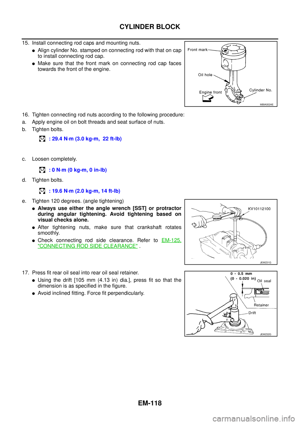
15. Install connecting rod caps and mounting nuts.
lAlign cylinder No. stamped on connecting rod with that on cap
to install connecting rod cap.
lMake sure that the front mark on connecting rod cap faces
towards the front of the engine.
16. Tighten connecting rod nuts according to the following procedure:
a. Apply engine oil on bolt threads and seat surface of nuts.
b. Tighten bolts.
c. Loosen completely.
d. Tighten bolts.
e. Tighten 120 degrees. (angle tightening)
lAlways use either the angle wrench [SST] or protractor
during angular tightening. Avoid tightening based on
visual checks alone.
lAfter tightening nuts, make sure that crankshaft rotates
smoothly.
lCheck connecting rod side clearance. Refer toEM-125,
"CONNECTING ROD SIDE CLEARANCE".
17. Press fit rear oil seal into rear oil seal retainer.
lUsing the drift [105 mm (4.13 in) dia.], press fit so that the
dimension is as specified in the figure.
lAvoid inclined fitting. Force fit perpendicularly.
MBIA0024E
: 29.4 N·m (3.0 kg-m, 22 ft-lb)
:0N·m(0kg-m,0in-lb)
: 19.6 N·m (2.0 kg-m, 14 ft-lb)
JEM231G
JEM232G
Page 1538 of 3171
FAX-6
WHEEL HUB
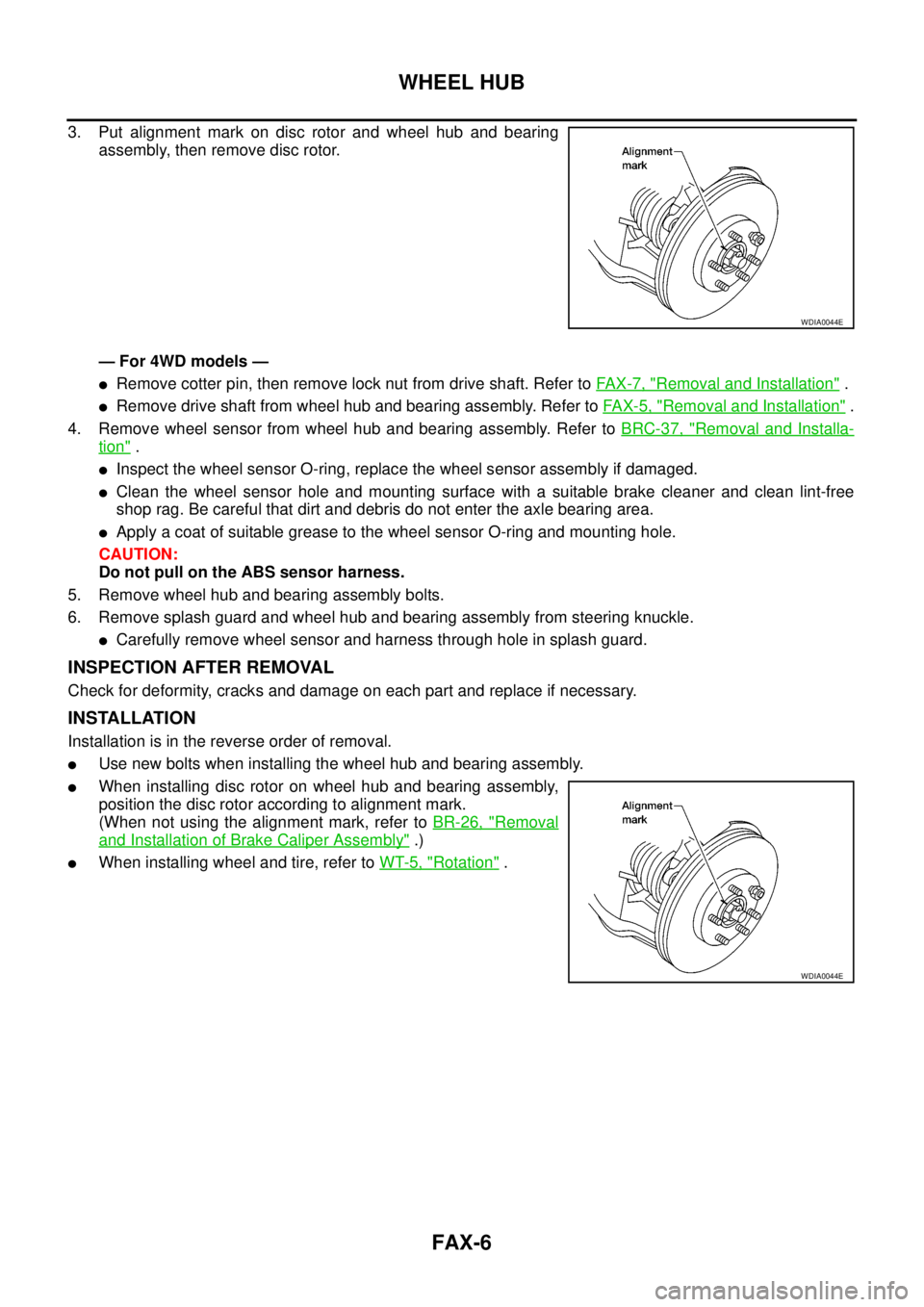
3. Put alignment mark on disc rotor and wheel hub and bearing
assembly, then remove disc rotor.
— For 4WD models —
lRemove cotter pin, then remove lock nut from drive shaft. Refer toFA X - 7 , "Removal and Installation".
lRemove drive shaft from wheel hub and bearing assembly. Refer toFAX-5, "Removal and Installation".
4. Remove wheel sensor from wheel hub and bearing assembly. Refer toBRC-37, "
Removal and Installa-
tion".
lInspect the wheel sensor O-ring, replace the wheel sensor assembly if damaged.
lClean the wheel sensor hole and mounting surface with a suitable brake cleaner and clean lint-free
shop rag. Be careful that dirt and debris do not enter the axle bearing area.
lApply a coat of suitable grease to the wheel sensor O-ring and mounting hole.
CAUTION:
Do not pull on the ABS sensor harness.
5. Remove wheel hub and bearing assembly bolts.
6. Remove splash guard and wheel hub and bearing assembly from steering knuckle.
lCarefully remove wheel sensor and harness through hole in splash guard.
INSPECTION AFTER REMOVAL
Check for deformity, cracks and damage on each part and replace if necessary.
INSTALLATION
Installation is in the reverse order of removal.
lUse new bolts when installing the wheel hub and bearing assembly.
lWhen installing disc rotor on wheel hub and bearing assembly,
position the disc rotor according to alignment mark.
(When not using the alignment mark, refer toBR-26, "
Removal
and Installation of Brake Caliper Assembly".)
lWhen installing wheel and tire, refer toWT-5, "Rotation".
WDIA0044E
WDIA0044E
Page 1541 of 3171
DRIVE SHAFT
FAX-9
C
E
F
G
H
I
J
K
L
MA
B
FA X
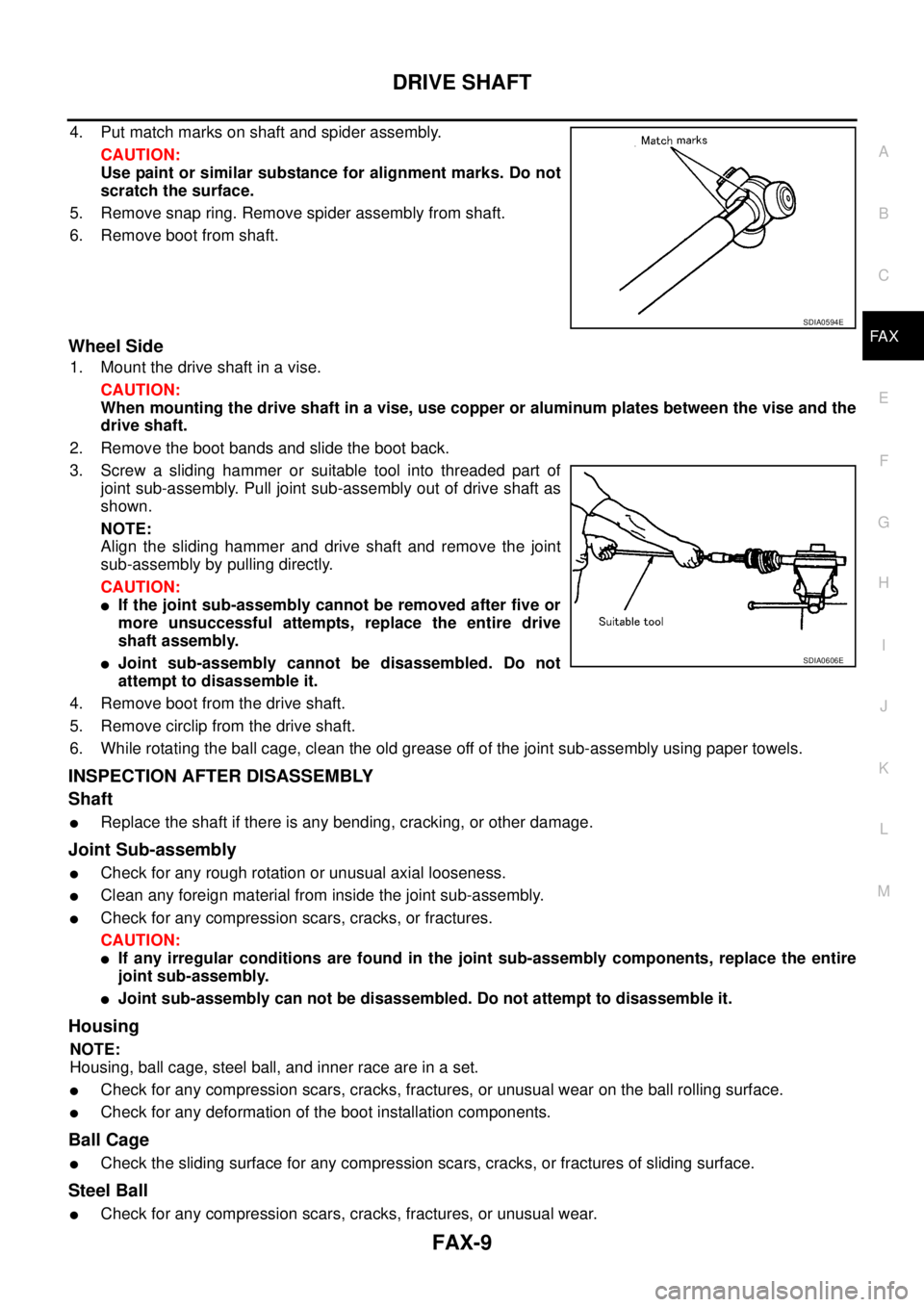
4. Put match marks on shaft and spider assembly.
CAUTION:
Use paint or similar substance for alignment marks. Do not
scratch the surface.
5. Remove snap ring. Remove spider assembly from shaft.
6. Remove boot from shaft.
Wheel Side
1. Mount the drive shaft in a vise.
CAUTION:
When mounting the drive shaft in a vise, use copper or aluminum plates between the vise and the
drive shaft.
2. Remove the boot bands and slide the boot back.
3. Screw a sliding hammer or suitable tool into threaded part of
joint sub-assembly. Pull joint sub-assembly out of drive shaft as
shown.
NOTE:
Align the sliding hammer and drive shaft and remove the joint
sub-assembly by pulling directly.
CAUTION:
lIf the joint sub-assembly cannot be removed after five or
more unsuccessful attempts, replace the entire drive
shaft assembly.
lJoint sub-assembly cannot be disassembled. Do not
attempt to disassemble it.
4. Remove boot from the drive shaft.
5. Remove circlip from the drive shaft.
6. While rotating the ball cage, clean the old grease off of the joint sub-assembly using paper towels.
INSPECTION AFTER DISASSEMBLY
Shaft
lReplace the shaft if there is any bending, cracking, or other damage.
Joint Sub-assembly
lCheck for any rough rotation or unusual axial looseness.
lClean any foreign material from inside the joint sub-assembly.
lCheck for any compression scars, cracks, or fractures.
CAUTION:
lIf any irregular conditions are found in the joint sub-assembly components, replace the entire
joint sub-assembly.
lJoint sub-assembly can not be disassembled. Do not attempt to disassemble it.
Housing
NOTE:
Housing, ball cage, steel ball, and inner race are in a set.
lCheck for any compression scars, cracks, fractures, or unusual wear on the ball rolling surface.
lCheck for any deformation of the boot installation components.
Ball Cage
lCheck the sliding surface for any compression scars, cracks, or fractures of sliding surface.
Steel Ball
lCheck for any compression scars, cracks, fractures, or unusual wear.
SDIA0594E
SDIA0606E
Page 1558 of 3171
FFD-12
FRONT OIL SEAL
3. Apply anti-corrosion oil to the thread and seat of new drive pin-
ion lock nut, and temporarily tighten drive pinion lock nut to drive
pinion.
CAUTION:
Do not reuse drive pinion lock nut.
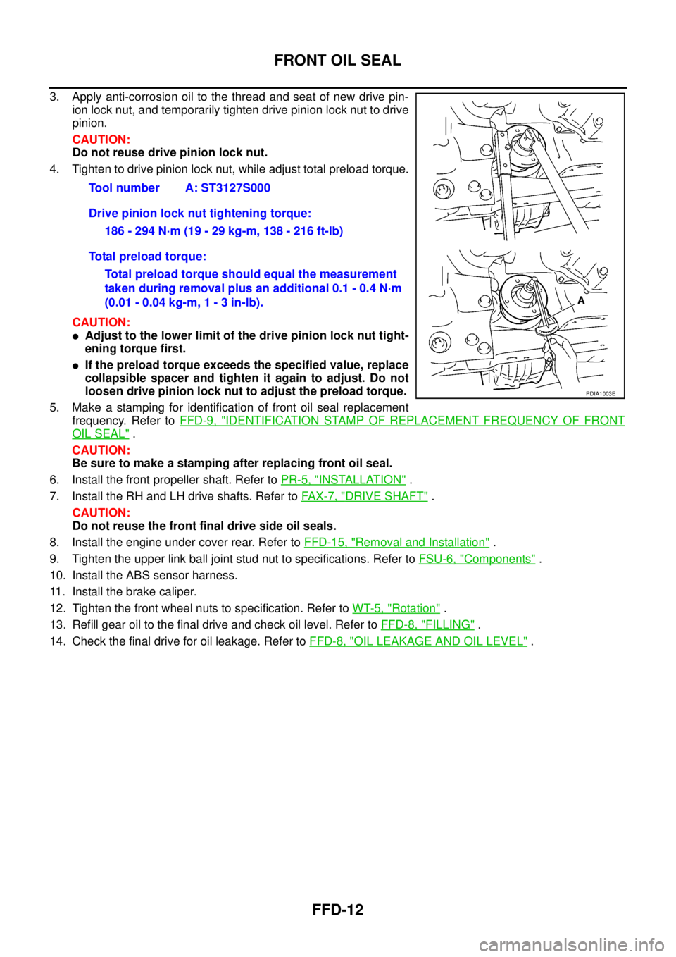
4. Tighten to drive pinion lock nut, while adjust total preload torque.
CAUTION:
lAdjust to the lower limit of the drive pinion lock nut tight-
ening torque first.
lIf the preload torque exceeds the specified value, replace
collapsible spacer and tighten it again to adjust. Do not
loosen drive pinion lock nut to adjust the preload torque.
5. Make a stamping for identification of front oil seal replacement
frequency. Refer toFFD-9, "
IDENTIFICATION STAMP OF REPLACEMENT FREQUENCY OF FRONT
OIL SEAL".
CAUTION:
Be sure to make a stamping after replacing front oil seal.
6. Install the front propeller shaft. Refer toPR-5, "
INSTALLATION".
7. Install the RH and LH drive shafts. Refer toFA X - 7 , "
DRIVE SHAFT".
CAUTION:
Do not reuse the front final drive side oil seals.
8. Install the engine under cover rear. Refer toFFD-15, "
Removal and Installation".
9. Tighten the upper link ball joint stud nut to specifications. Refer toFSU-6, "
Components".
10. Install the ABS sensor harness.
11. Install the brake caliper.
12. Tighten the front wheel nuts to specification. Refer toWT-5, "
Rotation".
13. Refill gear oil to the final drive and check oil level. Refer toFFD-8, "
FILLING".
14. Check the final drive for oil leakage. Refer toFFD-8, "
OIL LEAKAGE AND OIL LEVEL". Tool number A: ST3127S000
Drive pinion lock nut tightening torque:
186 - 294 N·m (19 - 29 kg-m, 138 - 216 ft-lb)
Total preload torque:
Total preload torque should equal the measurement
taken during removal plus an additional 0.1 - 0.4 N·m
(0.01 - 0.04 kg-m, 1 - 3 in-lb).
PDIA1003E
Page 1559 of 3171
SIDE OIL SEAL
FFD-13
C
E
F
G
H
I
J
K
L
MA
B
FFD
SIDE OIL SEALPFP:33142
Removal and InstallationEDS00354
REMOVAL
1. Remove the front wheels and tires using power tool.
2. Without disassembling the hydraulic lines, remove the caliper torque member bolts using power tool.
Then reposition the brake caliper aside using suitable wire. Refer toBR-26, "
Removal and Installation of
Brake Caliper Assembly".
CAUTION:
Do not press the brake pedal while brake caliper is removed.
3. Remove the ABS sensor harness from the mount on the knuckle.
CAUTION:
Do not pull on the ABS sensor harness.
4. Support the lower link using a suitable jack.
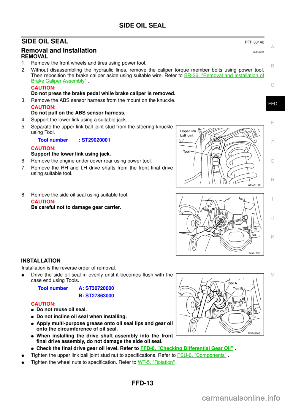
5. Separate the upper link ball joint stud from the steering knuckle
using Tool.
CAUTION:
Support the lower link using jack.
6. Remove the engine under cover rear using power tool.
7. Remove the RH and LH drive shafts from the front final drive
using suitable tool.
8. Remove the side oil seal using suitable tool.
CAUTION:
Be careful not to damage gear carrier.
INSTALLATION
Installation is the reverse order of removal.
lDrive the side oil seal in evenly until it becomes flush with the
case end using Tools.
CAUTION:
lDo not reuse oil seal.
lDo not incline oil seal when installing.
lApply multi-purpose grease onto oil seal lips and gear oil
onto the circumference of oil seal.
lWhen installing the drive shaft assembly into the front
final drive assembly, do not damage the side oil seal.
lCheck the final drive gear oil level. Refer toFFD-8, "Checking Differential Gear Oil".
lTighten the upper link ball joint stud nut to specifications. Refer toFSU-6, "Components".
lTighten the wheel nuts to specification. Refer toWT-5, "Rotation". Tool number : ST29020001
WEIA0119E
LDIA0173E
Tool number A: ST30720000
B: ST27863000
PDIA0826E
Page 1562 of 3171
FFD-16
FRONT FINAL DRIVE ASSEMBLY
CAUTION:
Do not pull on the ABS sensor harness.
4. Support the lower link using a suitable jack.
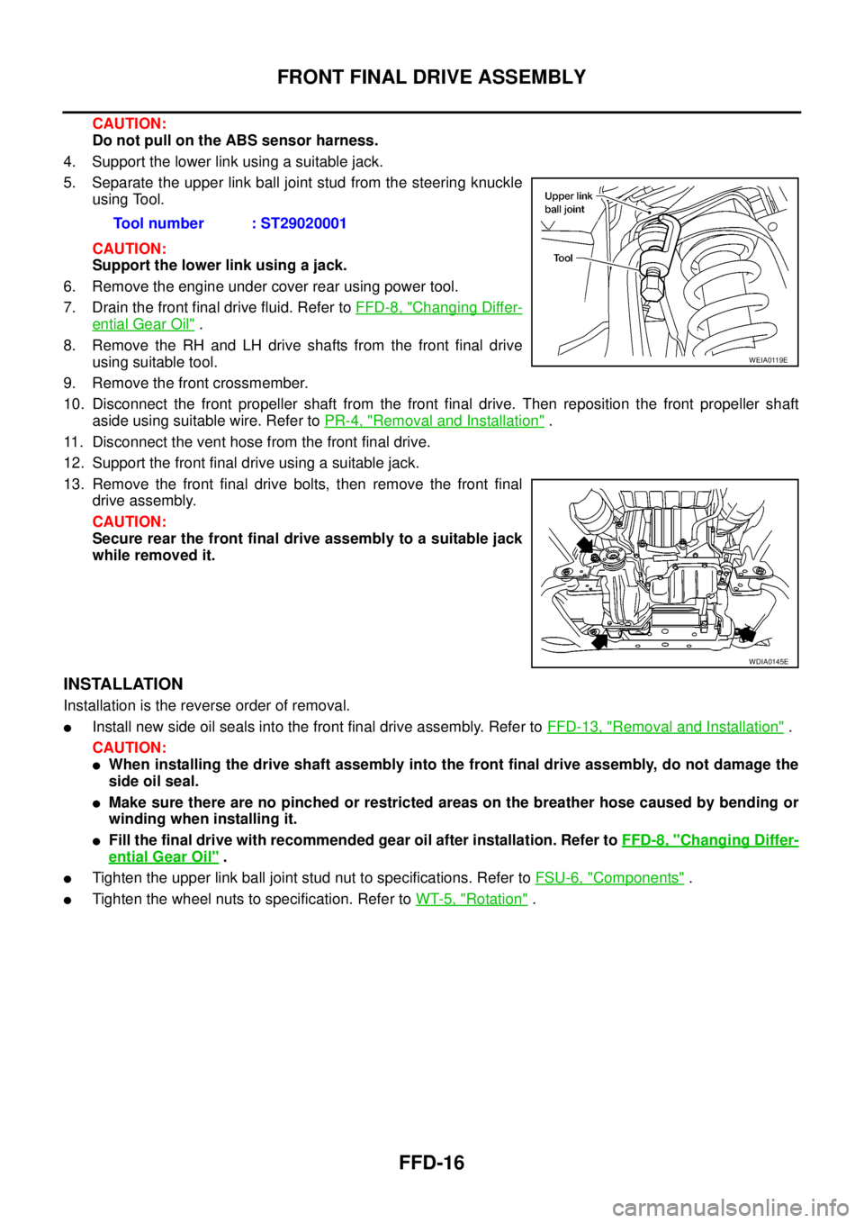
5. Separate the upper link ball joint stud from the steering knuckle
using Tool.
CAUTION:
Support the lower link using a jack.
6. Remove the engine under cover rear using power tool.
7. Drain the front final drive fluid. Refer toFFD-8, "
Changing Differ-
ential Gear Oil".
8. Remove the RH and LH drive shafts from the front final drive
using suitable tool.
9. Remove the front crossmember.
10. Disconnect the front propeller shaft from the front final drive. Then reposition the front propeller shaft
aside using suitable wire. Refer toPR-4, "
Removal and Installation".
11. Disconnect the vent hose from the front final drive.
12. Support the front final drive using a suitable jack.
13. Remove the front final drive bolts, then remove the front final
drive assembly.
CAUTION:
Secure rear the front final drive assembly to a suitable jack
while removed it.
INSTALLATION
Installation is the reverse order of removal.
lInstall new side oil seals into the front final drive assembly. Refer toFFD-13, "Removal and Installation".
CAUTION:
lWhen installing the drive shaft assembly into the front final drive assembly, do not damage the
side oil seal.
lMake sure there are no pinched or restricted areas on the breather hose caused by bending or
winding when installing it.
lFill the final drive with recommended gear oil after installation. Refer toFFD-8, "Changing Differ-
ential Gear Oil".
lTighten the upper link ball joint stud nut to specifications. Refer toFSU-6, "Components".
lTighten the wheel nuts to specification. Refer toWT-5, "Rotation". Tool number : ST29020001
WEIA0119E
WDIA0145E
Page 1607 of 3171
ON-VEHICLE SERVICE
FSU-7
C
D
F
G
H
I
J
K
L
MA
B
FSU
ON-VEHICLE SERVICEPFP:00000
Front Suspension PartsEES002KM
Check front suspension parts for excessive play, cracks, wear and
other damage.
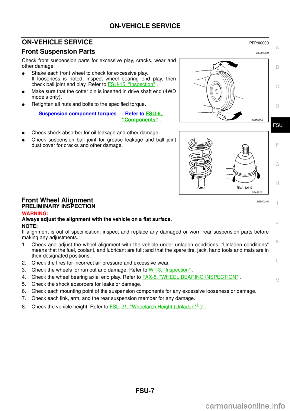
lShake each front wheel to check for excessive play.
If looseness is noted, inspect wheel bearing end play, then
check ball joint end play. Refer toFSU-15, "
Inspection".
lMake sure that the cotter pin is inserted in drive shaft end (4WD
models only).
lRetighten all nuts and bolts to the specified torque.
lCheck shock absorber for oil leakage and other damage.
lCheck suspension ball joint for grease leakage and ball joint
dust cover for cracks and other damage.
Front Wheel AlignmentEES002KN
PRELIMINARY INSPECTION
WARNING:
Always adjust the alignment with the vehicle on a flat surface.
NOTE:
If alignment is out of specification, inspect and replace any damaged or worn rear suspension parts before
making any adjustments.
1. Check and adjust the wheel alignment with the vehicle under unladen conditions. “Unladen conditions”
means that the fuel, coolant, and lubricant are full; and that the spare tire, jack, hand tools and mats are in
their designated positions.
2. Check the tires for incorrect air pressure and excessive wear.
3. Check the wheels for run out and damage. Refer toWT-3, "
Inspection".
4. Check the wheel bearing axial end play. Refer toFA X - 5 , "
WHEEL BEARING INSPECTION".
5. Check the shock absorbers for leaks or damage.
6. Check each mounting point of the suspension components for any excessive looseness or damage.
7. Check each link, arm, and the rear suspension member for any damage.
8. Check the vehicle height. Refer toFSU-21, "
Wheelarch Height (Unladen*1)". Suspension component torques : Refer toFSU-6,
"Components".SMA525A
SFA392B
Page 1610 of 3171
FSU-10
COIL SPRING AND SHOCK ABSORBER
COIL SPRING AND SHOCK ABSORBER
PFP:56210
Removal and InstallationEES002KO
REMOVAL
1. Remove the wheel.
2. Support the lower link using a suitable jack.
3. Remove connecting rod upper joints from stabilizer bar. Refer toFSU-6, "
Components".
lSwing stabilizer bar down, repositioning it out of the way to access shock absorber lower mount.
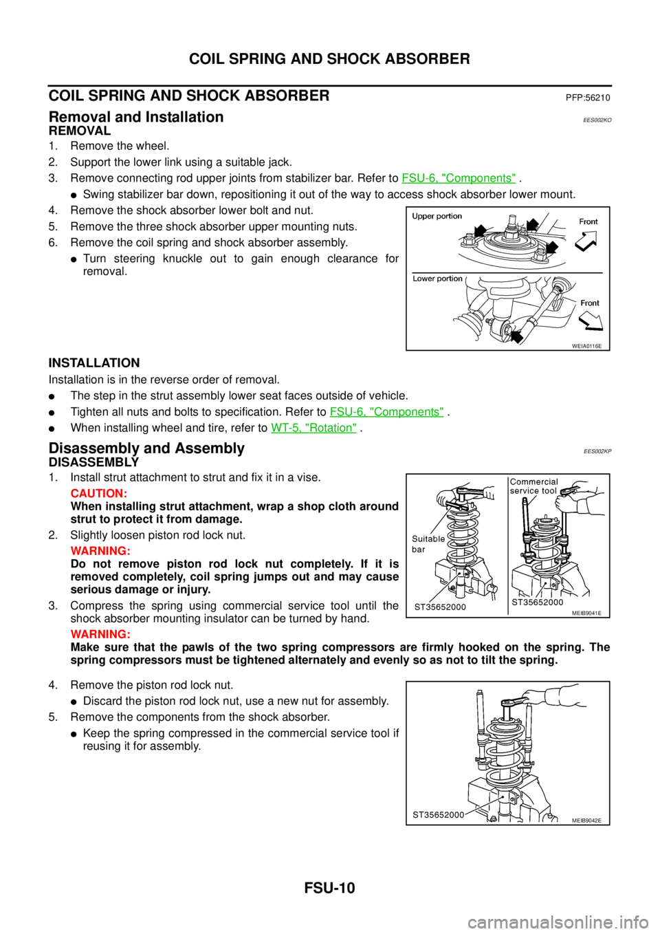
4. Remove the shock absorber lower bolt and nut.
5. Remove the three shock absorber upper mounting nuts.
6. Remove the coil spring and shock absorber assembly.
lTurn steering knuckle out to gain enough clearance for
removal.
INSTALLATION
Installation is in the reverse order of removal.
lThe step in the strut assembly lower seat faces outside of vehicle.
lTighten all nuts and bolts to specification. Refer toFSU-6, "Components".
lWhen installing wheel and tire, refer toWT-5, "Rotation".
Disassembly and AssemblyEES002KP
DISASSEMBLY
1. Install strut attachment to strut and fix it in a vise.
CAUTION:
When installing strut attachment, wrap a shop cloth around
strut to protect it from damage.
2. Slightly loosen piston rod lock nut.
WARNING:
Do not remove piston rod lock nut completely. If it is
removed completely, coil spring jumps out and may cause
serious damage or injury.
3. Compress the spring using commercial service tool until the
shock absorber mounting insulator can be turned by hand.
WARNING:
Make sure that the pawls of the two spring compressors are firmly hooked on the spring. The
spring compressors must be tightened alternately and evenly so as not to tilt the spring.
4. Remove the piston rod lock nut.
lDiscard the piston rod lock nut, use a new nut for assembly.
5. Remove the components from the shock absorber.
lKeep the spring compressed in the commercial service tool if
reusing it for assembly.
WEIA0116E
MEIB9041E
MEIB9042E