2005 NISSAN NAVARA tow
[x] Cancel search: towPage 15 of 3171
PRECAUTIONS
AT-7
D
E
F
G
H
I
J
K
L
MA
B
AT
PRECAUTIONSPFP:00001
Precautions for Supplemental Restraint System (SRS) “AIR BAG” and “SEAT
BELT PRE-TENSIONER”
ECS00IPT
The Supplemental Restraint System such as “AIR BAG” and “SEAT BELT PRE-TENSIONER”, used along
with a front seat belt, helps to reduce the risk or severity of injury to the driver and front passenger for certain
types of collision. Information necessary to service the system safely is included in the SRS and SB section of
this Service Manual.
WARNING:
lTo avoid rendering the SRS inoperative, which could increase the risk of personal injury or death
in the event of a collision which would result in air bag inflation, all maintenance must be per-
formed by an authorized NISSAN/INFINITI dealer.
lImproper maintenance, including incorrect removal and installation of the SRS, can lead to per-
sonal injury caused by unintentional activation of the system. For removal of Spiral Cable and Air
Bag Module, see the SRS section.
lDo not use electrical test equipment on any circuit related to the SRS unless instructed to in this
Service Manual. SRS wiring harnesses can be identified by yellow and/or orange harnesses or
harness connectors.
PrecautionsECS00IPR
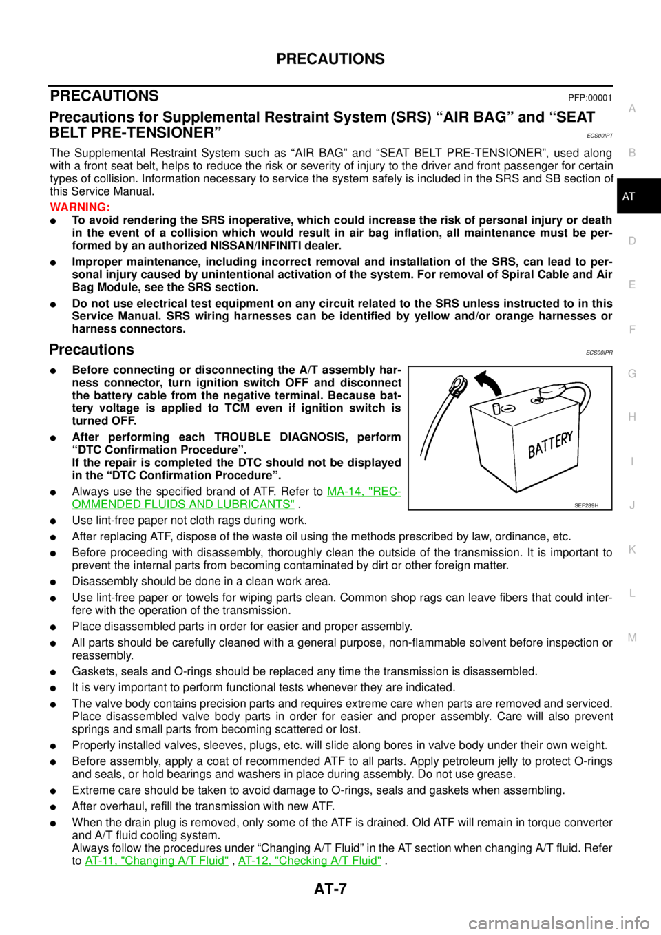
lBefore connecting or disconnecting the A/T assembly har-
ness connector, turn ignition switch OFF and disconnect
the battery cable from the negative terminal. Because bat-
tery voltage is applied to TCM even if ignition switch is
turned OFF.
lAfter performing each TROUBLE DIAGNOSIS, perform
“DTC Confirmation Procedure”.
If the repair is completed the DTC should not be displayed
in the “DTC Confirmation Procedure”.
lAlways use the specified brand of ATF. Refer toMA-14, "REC-
OMMENDED FLUIDS AND LUBRICANTS".
lUse lint-free paper not cloth rags during work.
lAfter replacing ATF, dispose of the waste oil using the methods prescribed by law, ordinance, etc.
lBefore proceeding with disassembly, thoroughly clean the outside of the transmission. It is important to
prevent the internal parts from becoming contaminated by dirt or other foreign matter.
lDisassembly should be done in a clean work area.
lUse lint-free paper or towels for wiping parts clean. Common shop rags can leave fibers that could inter-
fere with the operation of the transmission.
lPlace disassembled parts in order for easier and proper assembly.
lAll parts should be carefully cleaned with a general purpose, non-flammable solvent before inspection or
reassembly.
lGaskets, seals and O-rings should be replaced any time the transmission is disassembled.
lIt is very important to perform functional tests whenever they are indicated.
lThe valve body contains precision parts and requires extreme care when parts are removed and serviced.
Place disassembled valve body parts in order for easier and proper assembly. Care will also prevent
springs and small parts from becoming scattered or lost.
lProperly installed valves, sleeves, plugs, etc. will slide along bores in valve body under their own weight.
lBefore assembly, apply a coat of recommended ATF to all parts. Apply petroleum jelly to protect O-rings
and seals, or hold bearings and washers in place during assembly. Do not use grease.
lExtreme care should be taken to avoid damage to O-rings, seals and gaskets when assembling.
lAfter overhaul, refill the transmission with new ATF.
lWhen the drain plug is removed, only some of the ATF is drained. Old ATF will remain in torque converter
and A/T fluid cooling system.
Always follow the procedures under “Changing A/T Fluid” in the AT section when changing A/T fluid. Refer
toAT-11, "
Changing A/T Fluid",AT-12, "Checking A/T Fluid".
SEF289H
Page 42 of 3171

AT-34
TROUBLE DIAGNOSIS
TROUBLE DIAGNOSIS
PFP:00004
DTC Inspection Priority ChartECS00FWV
If some DTCs are displayed at the same time, perform inspections one by one based on the following priority
chart.
NOTE:
If DTC “U1000 CAN COMM CIRCUIT” is displayed with other DTCs, first perform the trouble diagnosis
for “DTC U1000 CAN COMMUNICATION LINE”. Refer toAT-91
.
Fail-safeECS00FWW
The TCM has an electrical fail-safe mode. This mode makes it possible to operate even if there is an error in a
main electronic control input/output signal circuit. In fail-safe mode A/T is fixed in 2nd, 4th or 5th (depending
on the breakdown position), so the customer should feel “slipping” or “poor acceleration”.
Even when the electronic circuits are normal, under special conditions (for example, when slamming on the
brake with the wheels spinning drastically and stopping the tire rotation), the transmission can go into fail-safe
mode. If this happens, switch OFF the ignition switch for 10 seconds, then switch it ON again to return to the
normal shift pattern. Therefore, the customer's vehicle has returned to normal, so handle according toAT- 3 7 ,
"WORK FLOW".
FAIL-SAFE FUNCTION
If any malfunction occurs in a sensor or solenoid, this function controls the A/T to mark driving possible.
Vehicle Speed Sensor
Signals are input from two systems - from vehicle speed sensor A/T (revolution sensor) installed on the A/T
and from combination meter so normal driving is possible even if there is a malfunction in one of the systems.
And if vehicle speed sensor A/T (revolution sensor) has unusual cases, 5th gear is prohibited.
Accelerator Pedal Position Sensor
If there is a malfunction in one of the systems, the accelerator opening angle is controlled by ECM according
to a pre-determined accelerator angle to make driving possible. And if there are malfunctions in tow systems,
the engine speed is fixed by ECM to a pre-determined engine speed to make driving possible.
PNP Switch
In the unlikely event that a malfunction signal enters the TCM, the position indicator is switched OFF, the
starter relay is switched OFF (starter starting is disabled), the back-up lamp relay switched OFF (back-up lamp
is OFF) and the position is fixed to the “D” position to make driving possible.
Starter Relay
The starter relay is switched OFF. (Starter starting is disabled.)
Priority Detected items (DTC)
1 U1000 CAN communication line
2 Except above
Page 232 of 3171
AT-224
ON-VEHICLE SERVICE
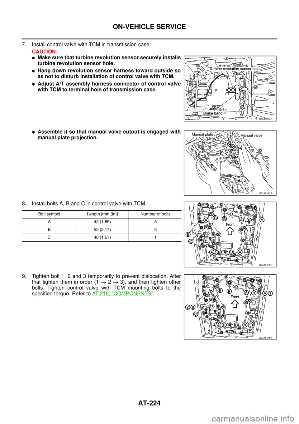
7. Install control valve with TCM in transmission case.
CAUTION:
lMake sure that turbine revolution sensor securely installs
turbine revolution sensor hole.
lHang down revolution sensor harness toward outside so
as not to disturb installation of control valve with TCM.
lAdjust A/T assembly harness connector of control valve
with TCM to terminal hole of transmission case.
lAssemble it so that manual valve cutout is engaged with
manual plate projection.
8. Install bolts A, B and C in control valve with TCM.
9. Tighten bolt 1, 2 and 3 temporarily to prevent dislocation. After
that tighten them in order (1®2®3), and then tighten other
bolts. Tighten control valve with TCM mounting bolts to the
specified torque. Refer toAT- 2 1 8 , "
COMPONENTS".
SCIA5034E
SCIA5142E
Bolt symbol Length [mm (in)] Number of bolts
A 42 (1.65) 5
B 55 (2.17) 6
C 40 (1.57) 1
SCIA5139E
SCIA5140E
Page 253 of 3171
A/T FLUID COOLER
AT-245
D
E
F
G
H
I
J
K
L
MA
B
AT
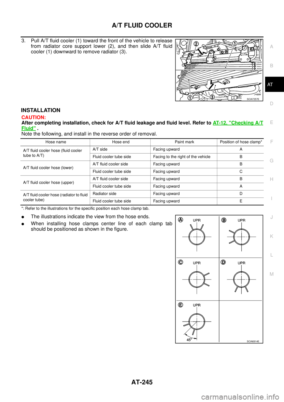
3. Pull A/T fluid cooler (1) toward the front of the vehicle to release
from radiator core support lower (2), and then slide A/T fluid
cooler (1) downward to remove radiator (3).
INSTALLATION
CAUTION:
After completing installation, check for A/T fluid leakage and fluid level. Refer toAT-12, "
Checking A/T
Fluid".
Note the following, and install in the reverse order of removal.
*: Refer to the illustrations for the specific position each hose clamp tab.
lThe illustrations indicate the view from the hose ends.
lWhen installing hose clamps center line of each clamp tab
should be positioned as shown in the figure.
SCIA7257E
Hose name Hose end Paint mark Position of hose clamp*
A/T fluid cooler hose (fluid cooler
tube to A/T)A/T side Facing upward A
Fluid cooler tube side Facing to the right of the vehicle B
A/T fluid cooler hose (lower)A/T fluid cooler side Facing upward B
Fluid cooler tube side Facing upward C
A/T fluid cooler hose (upper)A/T fluid cooler side Facing upward B
Fluid cooler tube side Facing upward A
A/T fluid cooler hose (radiator to fluid
cooler tube)Radiator side Facing upward D
Fluid cooler tube side Facing upward E
SCIA6914E
Page 327 of 3171
ASSEMBLY
AT-319
D
E
F
G
H
I
J
K
L
MA
B
AT
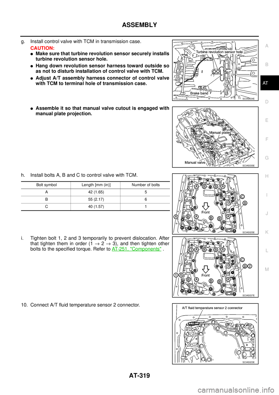
g. Install control valve with TCM in transmission case.
CAUTION:
lMake sure that turbine revolution sensor securely installs
turbine revolution sensor hole.
lHang down revolution sensor harness toward outside so
as not to disturb installation of control valve with TCM.
lAdjust A/T assembly harness connector of control valve
with TCM to terminal hole of transmission case.
lAssemble it so that manual valve cutout is engaged with
manual plate projection.
h. Install bolts A, B and C to control valve with TCM.
i. Tighten bolt 1, 2 and 3 temporarily to prevent dislocation. After
that tighten them in order (1®2®3), and then tighten other
bolts to the specified torque. Refer toAT- 2 5 1 , "
Components".
10. Connect A/T fluid temperature sensor 2 connector.
SCIA5034E
SCIA5035E
Bolt symbol Length [mm (in)] Number of bolts
A42(1.65) 5
B55(2.17) 6
C40(1.57) 1
SCIA5025E
SCIA5037E
SCIA5023E
Page 476 of 3171
ATC-142
REFRIGERANT LINES
Removal and Installation for Compressor
EJS006CN
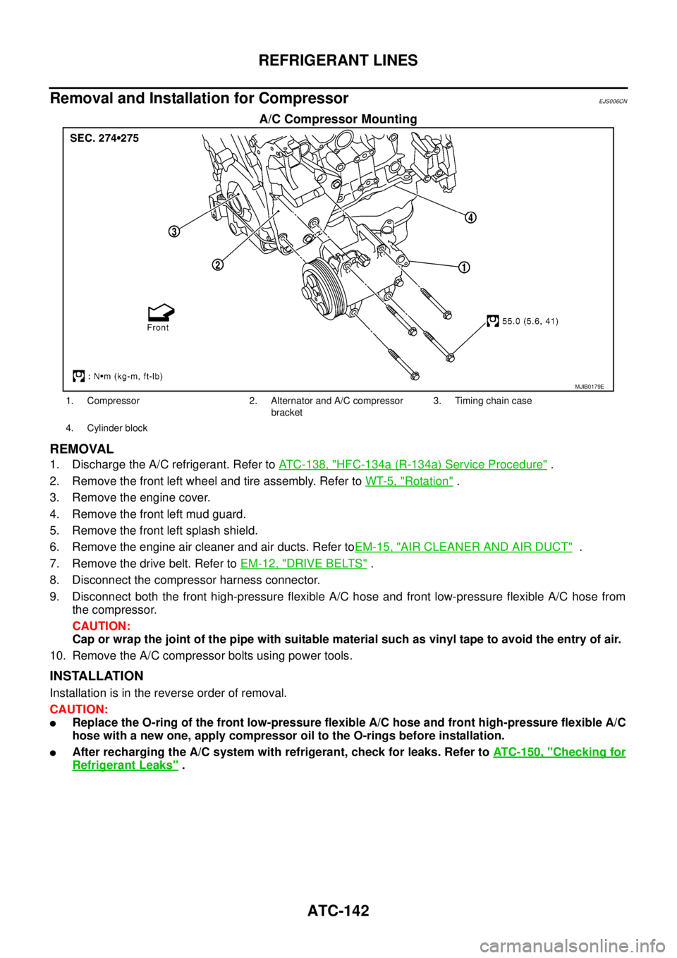
A/C Compressor Mounting
REMOVAL
1. Discharge the A/C refrigerant. Refer toATC-138, "HFC-134a (R-134a) Service Procedure".
2. Remove the front left wheel and tire assembly. Refer toWT-5, "
Rotation".
3. Remove the engine cover.
4. Remove the front left mud guard.
5. Remove the front left splash shield.
6. Remove the engine air cleaner and air ducts. Refer toEM-15, "
AIR CLEANER AND AIR DUCT".
7. Remove the drive belt. Refer toEM-12, "
DRIVE BELTS".
8. Disconnect the compressor harness connector.
9. Disconnect both the front high-pressure flexible A/C hose and front low-pressure flexible A/C hose from
the compressor.
CAUTION:
Cap or wrap the joint of the pipe with suitable material such as vinyl tape to avoid the entry of air.
10. Remove the A/C compressor bolts using power tools.
INSTALLATION
Installation is in the reverse order of removal.
CAUTION:
lReplace the O-ring of the front low-pressure flexible A/C hose and front high-pressure flexible A/C
hose with a new one, apply compressor oil to the O-rings before installation.
lAfter recharging the A/C system with refrigerant, check for leaks. Refer toATC-150, "Checking for
Refrigerant Leaks".
MJIB0179E
1. Compressor 2. Alternator and A/C compressor
bracket3. Timing chain case
4. Cylinder block
Page 480 of 3171
ATC-146
REFRIGERANT LINES
BREAK-IN OPERATION
When replacing compressor clutch assembly, always conduct the break-in operation. This is done by engag-
ing and disengaging the clutch about 30 times. Break-in operation raises the level of transmitted torque.
Removal and Installation for High-pressure Flexible A/C HoseEJS006CP
REMOVAL
1. Remove the front left wheel and tire assembly. Refer toWT-5, "Rotation".
2. Remove the front left mud guard.
3. Remove the front left splash shield.
4. Discharge the refrigerant. Refer toATC-138, "
HFC-134a (R-134a) Service Procedure".
5. Remove the high-pressure flexible A/C hose. Refer toATC-140, "
Components".
CAUTION:
Cap or wrap the joint of the pipe with suitable material such as vinyl tape to avoid the entry of air.
INSTALLATION
Installation is in the reverse order of removal.
Refer toATC-140, "
Components".
CAUTION:
lReplace the O-ring of the high-pressure flexible A/C hose with a new one, then apply compressor
oil to it for installation.
lAfter charging refrigerant, check for leaks.
Removal and Installation for High-pressure A/C PipeEJS006CQ
REMOVAL
1. Remove the front right wheel and tire assembly. Refer toWT-5, "Rotation".
2. Remove the front right mud guard.
3. Remove the front right splash shield.
4. Discharge the refrigerant. Refer toATC-138, "
HFC-134a (R-134a) Service Procedure".
5. Remove the low pressure A/C pipe. Refer toATC-147, "
Removal and Installation for Low-pressure A/C
Pipe".
6. Remove the high-pressure A/C pipe. Refer toATC-146, "
Removal and Installation for High-pressure A/C
Pipe".
CAUTION:
Cap or wrap the joint of the pipe with suitable material such as vinyl tape to avoid the entry of air.
INSTALLATION
Installation is in the reverse order of removal.
Refer toATC-140, "
Components".
CAUTION:
lReplace the O-ring of the high-pressure A/C pipe with a new one, then apply compressor oil to it
for installation.
lAfter charging refrigerant, check for leaks.
Removal and Installation for Low-pressure Flexible A/C HoseEJS006CR
REMOVAL
1. Remove the front right wheel and tire assembly. Refer toWT-5, "Rotation".
2. Remove the front right mud guard.
3. Remove the front right splash shield.
4. Discharge the refrigerant. Refer toATC-138, "
HFC-134a (R-134a) Service Procedure".
CAUTION:
Cap or wrap the joint of the pipe with suitable material such as vinyl tape to avoid the entry of air.
5. Remove the low-pressure flexible A/C hose. Refer toATC-140, "
Components".
INSTALLATION
Installation is in the reverse order of removal.
Refer toATC-140, "
Components".
Page 559 of 3171
TROUBLE DIAGNOSIS
AV-71
C
D
E
F
G
H
I
J
L
MA
B
AV
THE CURRENT POSITION MARK SHOWS A POSITION THAT IS COMPLETELY INCORRECT.
In the following cases, the current location mark may be displayed in a location that is completely incorrect. If
so, perform position/direction correction.
lWhen location correction has not been done
–If GPS satellite reception is poor and the current location mark slips out of place, it may shift to a com-
pletely unexpected location and not return unless location correction is performed. The position will be
corrected if a GPS signal can be received.
lWhen vehicle has traveled by ferry, or when vehicle has been towed.
VehicleUse of tire chains.
The vehicle mark may deviate from
the correct road.Drivethevehicleforawhile.Ifdis-
tance still deviates, adjust it with
the distance adjustment function. (If
tire chains are removed, recover
the original value.)
Use of tires other than the specified
sizeReplace all tires with the specified
size tire.
Malfunctioning air pressure of tireAdjust all tires to the specified air
pressure.
Replace tireDrive the vehicle for a while. If the
distance is still not in the correct
location, it adjusts with the distance
adjustment function.
Driving
mannerJust after the engine is startedIf vehicle is driven off just after the
engine is started when gyroscope
(angular speed sensor) correction is
not completed, the vehicle can can
be shown in the incorrect direction
and may deviate from the correct
location.Wait for a short while before driving
after starting the engine.
Continuous driving without stoppingWhen driving long distances without
stopping, direction errors may accu-
mulate, and the current location
mark may deviate from the correct
road.Stop and adjust orientation.
Abusive drivingSpinning the wheels or engaging in
other kinds of abusive driving may
result in the system being unable
perform correct detection, and may
cause the vehicle mark to deviate
from the correct road.If after traveling about 10 km (6
MPH) the correct location has not
been restored, perform location
correction and, if necessary, direc-
tion correction.
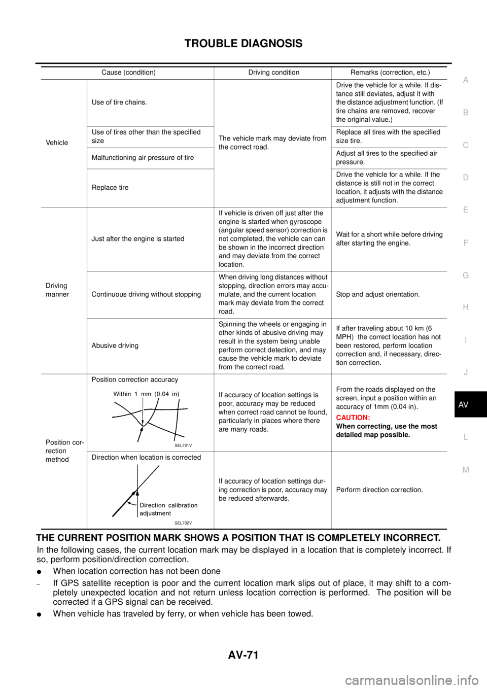
Position cor-
rection
methodPosition correction accuracy
If accuracy of location settings is
poor, accuracy may be reduced
when correct road cannot be found,
particularly in places where there
are many roads.From the roads displayed on the
screen, input a position within an
accuracy of 1mm (0.04 in).
CAUTION:
When correcting, use the most
detailed map possible.
Direction when location is corrected
If accuracy of location settings dur-
ing correction is poor, accuracy may
be reduced afterwards.Perform direction correction. Cause (condition) Driving condition Remarks (correction, etc.)
SEL701V
SEL702V