2005 NISSAN NAVARA steering
[x] Cancel search: steeringPage 1462 of 3171
EM-80
PRIMARY TIMING CHAIN
lRefer toGI-10, "Components"for symbol marks in the figure.
Removal and InstallationEBS01E69
CAUTION:
lAfter removing timing chain, do not turn crankshaft and camshaft separately, or valves will strike
piston heads.
lWhen installing camshafts, chain tensioners, oil seals or other sliding parts, lubricate contacting
surfaces with new engine oil.
REMOVAL
1. Remove power steering oil pump and power steering oil pump bracket. Refer toPS-25, "POWER STEER-
ING OIL PUMP".
2. Remove idler pulleys.
3. Remove rocker cover. Refer toEM-56, "
ROCKER COVER".
4. Remove oil pan (upper and lower). Refer toEM-36, "
OIL PAN AND OIL STRAINER".
5. Remove fuel injector. Refer toEM-44, "
INJECTION TUBE AND FUEL INJECTOR".
6. Remove secondary timing chain and associated parts. Refer toEM-73, "
SECONDARY TIMING CHAIN".
7. When removing rear chain case, remove camshaft sprockets. Refer toEM-59, "
CAMSHAFT".
8. Remove crankshaft pulley.
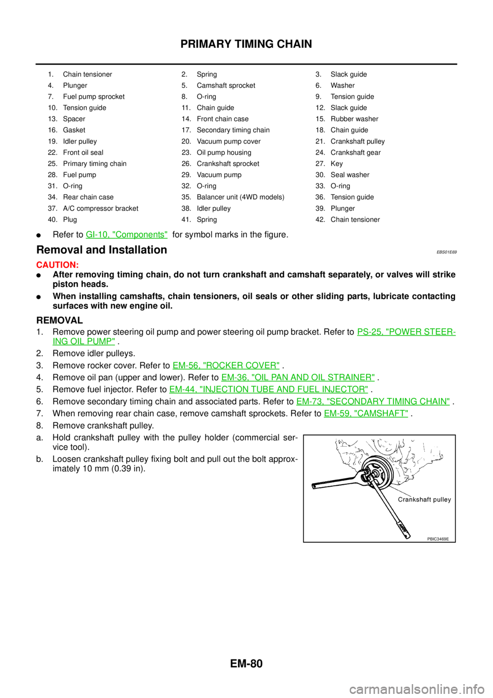
a. Hold crankshaft pulley with the pulley holder (commercial ser-
vice tool).
b. Loosen crankshaft pulley fixing bolt and pull out the bolt approx-
imately 10 mm (0.39 in).
1. Chain tensioner 2. Spring 3. Slack guide
4. Plunger 5. Camshaft sprocket 6. Washer
7. Fuel pump sprocket 8. O-ring 9. Tension guide
10. Tension guide 11. Chain guide 12. Slack guide
13. Spacer 14. Front chain case 15. Rubber washer
16. Gasket 17. Secondary timing chain 18. Chain guide
19. Idler pulley 20. Vacuum pump cover 21. Crankshaft pulley
22. Front oil seal 23. Oil pump housing 24. Crankshaft gear
25. Primary timing chain 26. Crankshaft sprocket 27. Key
28. Fuel pump 29. Vacuum pump 30. Seal washer
31. O-ring 32. O-ring 33. O-ring
34. Rear chain case 35. Balancer unit (4WD models) 36. Tension guide
37. A/C compressor bracket 38. Idler pulley 39. Plunger
40. Plug 41. Spring 42. Chain tensioner
PBIC3469E
Page 1469 of 3171
PRIMARY TIMING CHAIN
EM-87
C
D
E
F
G
H
I
J
K
L
MA
EM
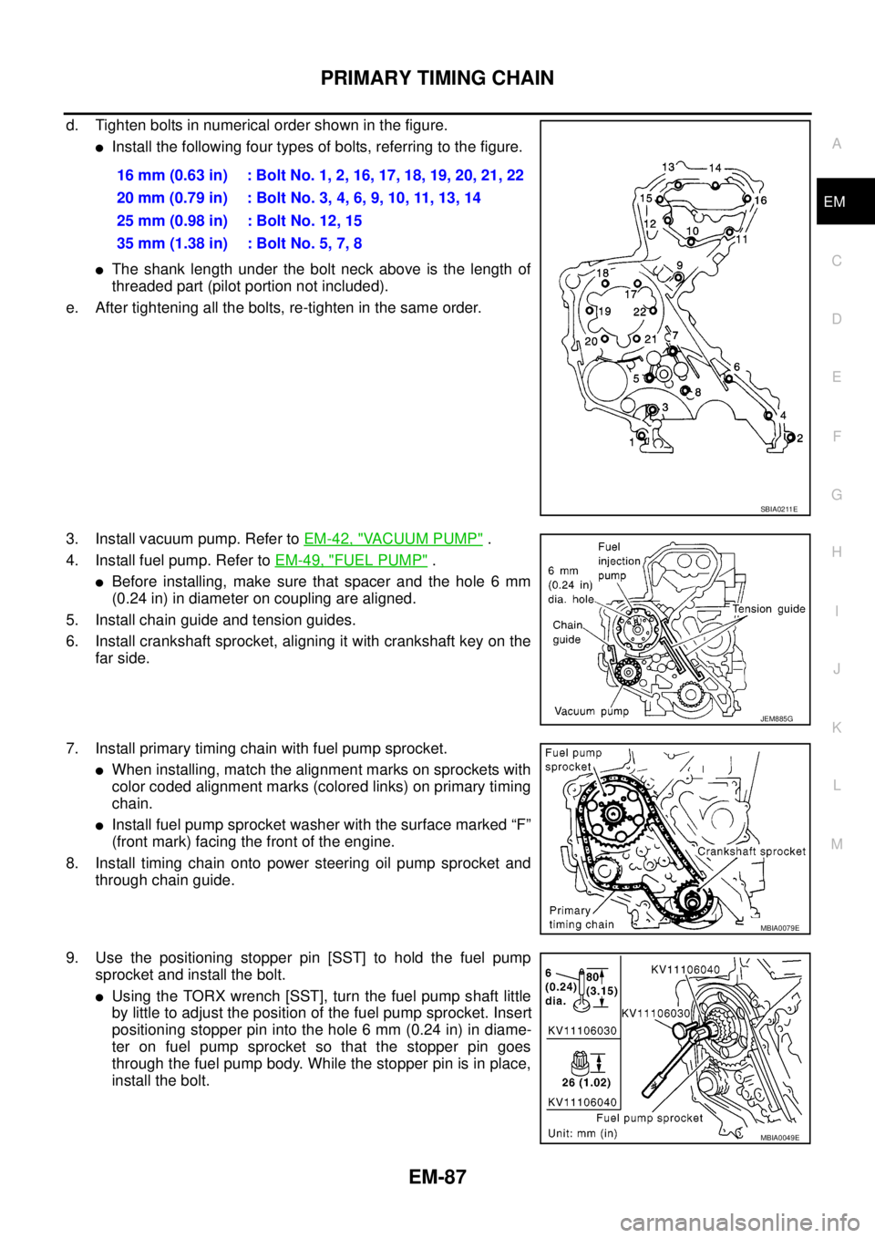
d. Tighten bolts in numerical order shown in the figure.
lInstall the following four types of bolts, referring to the figure.
lThe shank length under the bolt neck above is the length of
threaded part (pilot portion not included).
e. After tightening all the bolts, re-tighten in the same order.
3. Install vacuum pump. Refer toEM-42, "
VACUUM PUMP".
4. Install fuel pump. Refer toEM-49, "
FUEL PUMP".
lBefore installing, make sure that spacer and the hole 6 mm
(0.24 in) in diameter on coupling are aligned.
5. Install chain guide and tension guides.
6. Install crankshaft sprocket, aligning it with crankshaft key on the
far side.
7. Install primary timing chain with fuel pump sprocket.
lWhen installing, match the alignment marks on sprockets with
color coded alignment marks (colored links) on primary timing
chain.
lInstall fuel pump sprocket washer with the surface marked “F”
(front mark) facing the front of the engine.
8. Install timing chain onto power steering oil pump sprocket and
through chain guide.
9. Use the positioning stopper pin [SST] to hold the fuel pump
sprocket and install the bolt.
lUsing the TORX wrench [SST], turn the fuel pump shaft little
by little to adjust the position of the fuel pump sprocket. Insert
positioning stopper pin into the hole 6 mm (0.24 in) in diame-
ter on fuel pump sprocket so that the stopper pin goes
through the fuel pump body. While the stopper pin is in place,
install the bolt.16 mm (0.63 in) : Bolt No. 1, 2, 16, 17, 18, 19, 20, 21, 22
20mm(0.79in) :BoltNo.3,4,6,9,10,11,13,14
25 mm (0.98 in) : Bolt No. 12, 15
35 mm (1.38 in) : Bolt No. 5, 7, 8
SBIA0211E
JEM885G
MBIA0079E
MBIA0049E
Page 1473 of 3171
PRIMARY TIMING CHAIN
EM-91
C
D
E
F
G
H
I
J
K
L
MA
EM
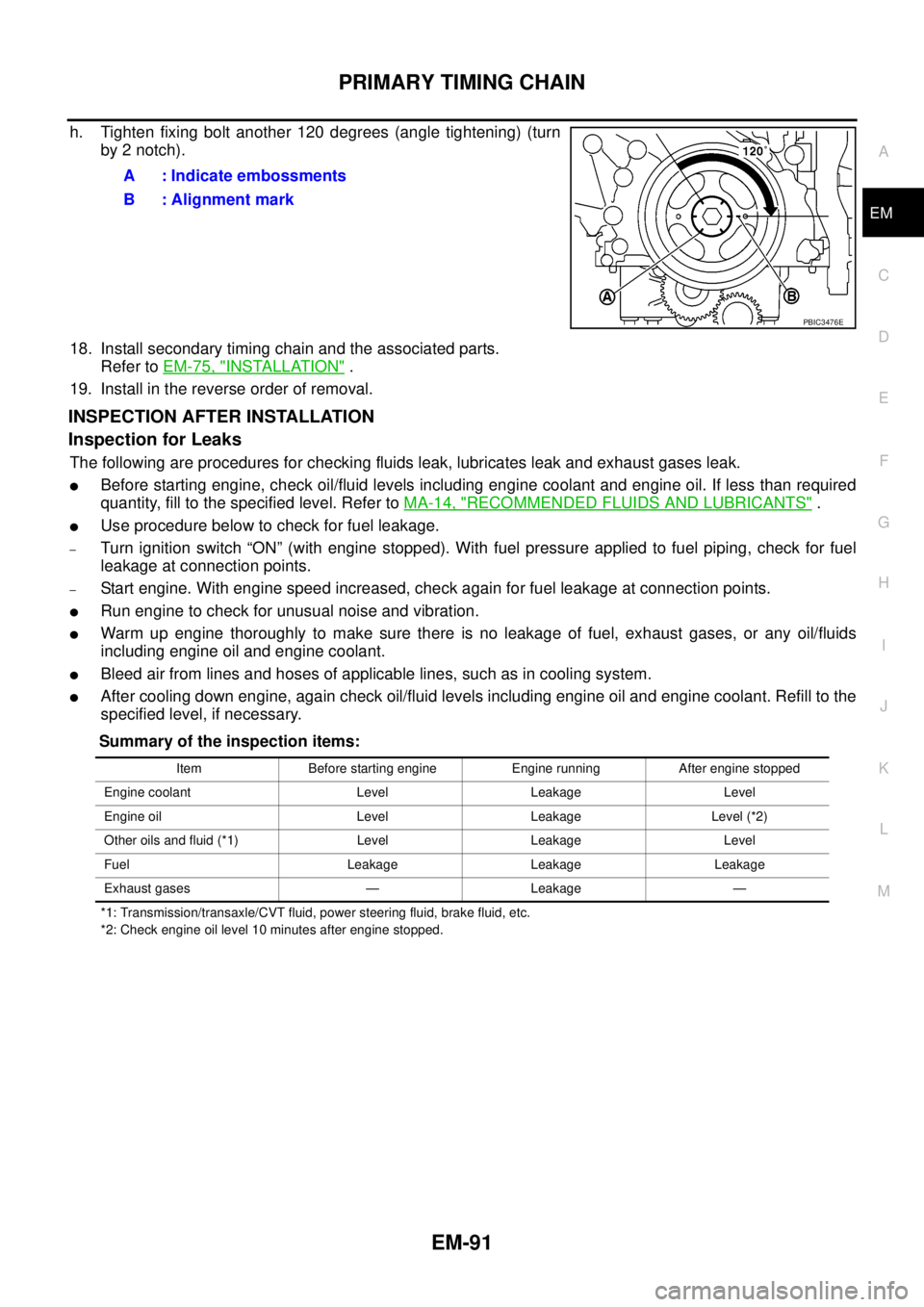
h. Tighten fixing bolt another 120 degrees (angle tightening) (turn
by 2 notch).
18. Install secondary timing chain and the associated parts.
Refer toEM-75, "
INSTALLATION".
19. Install in the reverse order of removal.
INSPECTION AFTER INSTALLATION
Inspection for Leaks
The following are procedures for checking fluids leak, lubricates leak and exhaust gases leak.
lBefore starting engine, check oil/fluid levels including engine coolant and engine oil. If less than required
quantity, fill to the specified level. Refer toMA-14, "
RECOMMENDED FLUIDS AND LUBRICANTS".
lUse procedure below to check for fuel leakage.
–Turn ignition switch “ON” (with engine stopped). With fuel pressure applied to fuel piping, check for fuel
leakage at connection points.
–Start engine. With engine speed increased, check again for fuel leakage at connection points.
lRun engine to check for unusual noise and vibration.
lWarm up engine thoroughly to make sure there is no leakage of fuel, exhaust gases, or any oil/fluids
including engine oil and engine coolant.
lBleed air from lines and hoses of applicable lines, such as in cooling system.
lAfter cooling down engine, again check oil/fluid levels including engine oil and engine coolant. Refill to the
specified level, if necessary.
Summary of the inspection items:
*1: Transmission/transaxle/CVT fluid, power steering fluid, brake fluid, etc.
*2: Check engine oil level 10 minutes after engine stopped.
A : Indicate embossments
B : Alignment mark
PBIC3476E
Item Before starting engine Engine running After engine stopped
Engine coolant Level Leakage Level
Engine oil Level Leakage Level (*2)
Other oils and fluid (*1) Level Leakage Level
Fuel Leakage Leakage Leakage
Exhaust gases — Leakage —
Page 1480 of 3171
EM-98
CYLINDER HEAD
lBefore installing, remove carbon depositing on mounting hole of glow plug with a reamer.
6. Install engine coolant temperature sensor.
7. Install in the reverse order of removal.
INSPECTION AFTER INSTALLATION
Inspection for Leaks
The following are procedures for checking fluids leak, lubricates leak and exhaust gases leak.
lBefore starting engine, check oil/fluid levels including engine coolant and engine oil. If less than required
quantity, fill to the specified level. Refer toMA-14, "
RECOMMENDED FLUIDS AND LUBRICANTS".
lUse procedure below to check for fuel leakage.
–Turn ignition switch “ON” (with engine stopped). With fuel pressure applied to fuel piping, check for fuel
leakage at connection points.
–Start engine. With engine speed increased, check again for fuel leakage at connection points.
lRun engine to check for unusual noise and vibration.
lWarm up engine thoroughly to make sure there is no leakage of fuel, exhaust gases, or any oil/fluids
including engine oil and engine coolant.
lBleed air from lines and hoses of applicable lines, such as in cooling system.
lAfter cooling down engine, again check oil/fluid levels including engine oil and engine coolant. Refill to the
specified level, if necessary.
Summary of the inspection items:
*1: Transmission/transaxle/CVT fluid, power steering fluid, brake fluid, etc.
*2: Check engine oil level 10 minutes after engine stopped.Item Before starting engine Engine running After engine stopped
Engine coolant Level Leakage Level
Engine oil Level Leakage Level (*2)
Other oils and fluid (*1) Level Leakage Level
Fuel Leakage Leakage Leakage
Exhaust gases — Leakage —
Page 1489 of 3171
ENGINE ASSEMBLY
EM-107
C
D
E
F
G
H
I
J
K
L
MA
EM
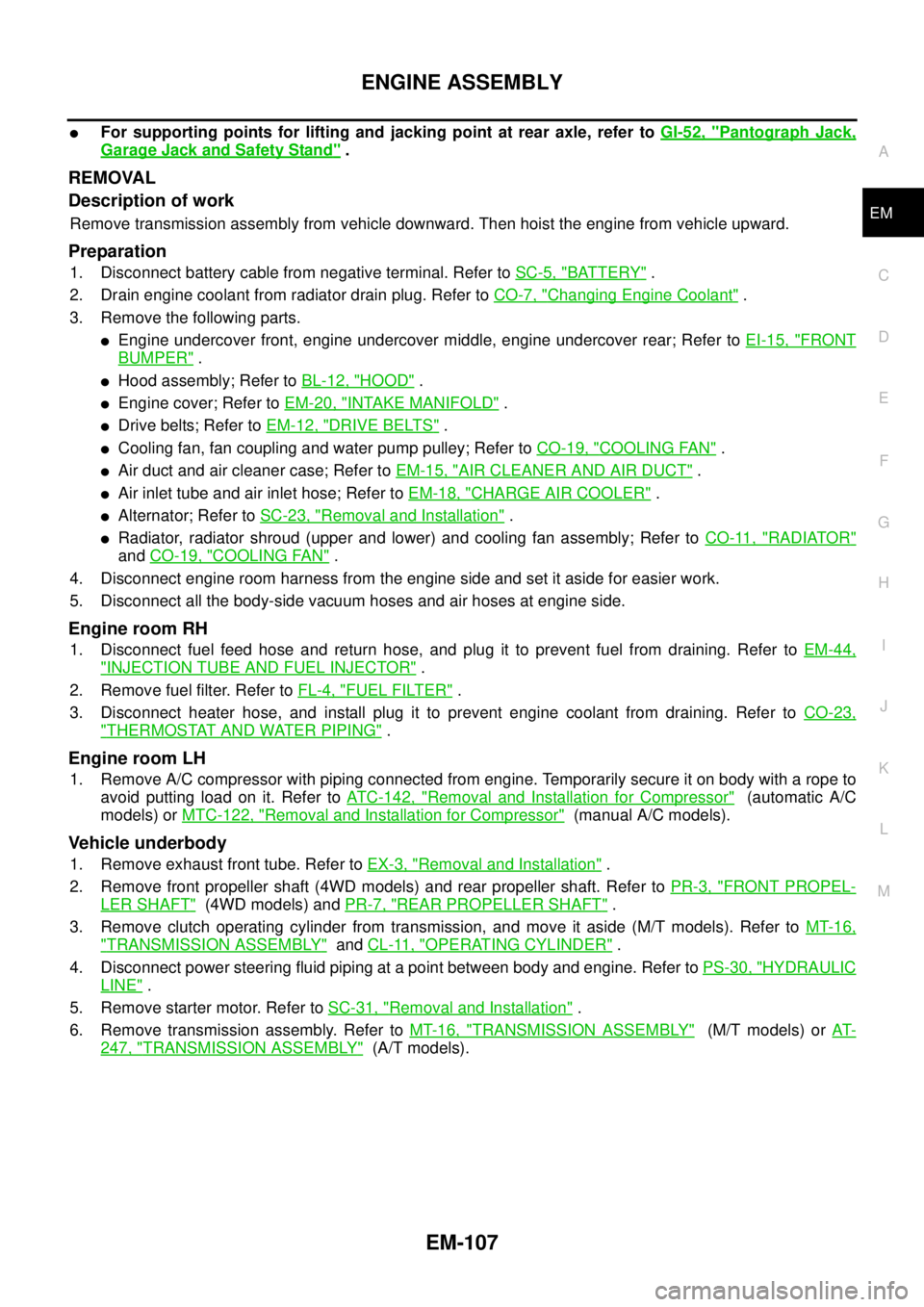
lFor supporting points for lifting and jacking point at rear axle, refer toGI-52, "Pantograph Jack,
Garage Jack and Safety Stand".
REMOVAL
Description of work
Remove transmission assembly from vehicle downward. Then hoist the engine from vehicle upward.
Preparation
1. Disconnect battery cable from negative terminal. Refer toSC-5, "BATTERY".
2. Drain engine coolant from radiator drain plug. Refer toCO-7, "
Changing Engine Coolant".
3. Remove the following parts.
lEngine undercover front, engine undercover middle, engine undercover rear; Refer toEI-15, "FRONT
BUMPER".
lHood assembly; Refer toBL-12, "HOOD".
lEngine cover; Refer toEM-20, "INTAKE MANIFOLD".
lDrive belts; Refer toEM-12, "DRIVE BELTS".
lCooling fan, fan coupling and water pump pulley; Refer toCO-19, "COOLING FAN".
lAir duct and air cleaner case; Refer toEM-15, "AIR CLEANER AND AIR DUCT".
lAir inlet tube and air inlet hose; Refer toEM-18, "CHARGE AIR COOLER".
lAlternator; Refer toSC-23, "Removal and Installation".
lRadiator, radiator shroud (upper and lower) and cooling fan assembly; Refer toCO-11, "RADIATOR"
andCO-19, "COOLING FAN".
4. Disconnect engine room harness from the engine side and set it aside for easier work.
5. Disconnect all the body-side vacuum hoses and air hoses at engine side.
Engine room RH
1. Disconnect fuel feed hose and return hose, and plug it to prevent fuel from draining. Refer toEM-44,
"INJECTION TUBE AND FUEL INJECTOR".
2. Remove fuel filter. Refer toFL-4, "
FUEL FILTER".
3. Disconnect heater hose, and install plug it to prevent engine coolant from draining. Refer toCO-23,
"THERMOSTAT AND WATER PIPING".
Engine room LH
1. Remove A/C compressor with piping connected from engine. Temporarily secure it on body with a rope to
avoid putting load on it. Refer toATC-142, "
Removal and Installation for Compressor"(automatic A/C
models) orMTC-122, "
Removal and Installation for Compressor"(manual A/C models).
Vehicle underbody
1. Remove exhaust front tube. Refer toEX-3, "Removal and Installation".
2. Remove front propeller shaft (4WD models) and rear propeller shaft. Refer toPR-3, "
FRONT PROPEL-
LER SHAFT"(4WD models) andPR-7, "REAR PROPELLER SHAFT".
3. Remove clutch operating cylinder from transmission, and move it aside (M/T models). Refer toMT-16,
"TRANSMISSION ASSEMBLY"andCL-11, "OPERATING CYLINDER".
4. Disconnect power steering fluid piping at a point between body and engine. Refer toPS-30, "
HYDRAULIC
LINE".
5. Remove starter motor. Refer toSC-31, "
Removal and Installation".
6. Remove transmission assembly. Refer toMT-16, "
TRANSMISSION ASSEMBLY"(M/T models) orAT-
247, "TRANSMISSION ASSEMBLY"(A/T models).
Page 1491 of 3171
ENGINE ASSEMBLY
EM-109
C
D
E
F
G
H
I
J
K
L
MA
EM
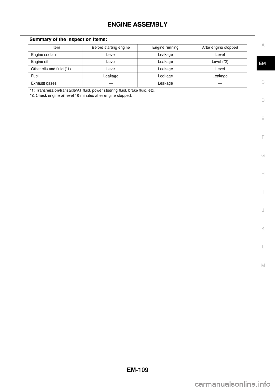
Summary of the inspection items:
*1: Transmission/transaxle/AT fluid, power steering fluid, brake fluid, etc.
*2: Check engine oil level 10 minutes after engine stopped.Item Before starting engine Engine running After engine stopped
Engine coolant Level Leakage Level
Engine oil Level Leakage Level (*2)
Other oils and fluid (*1) Level Leakage Level
Fuel Leakage Leakage Leakage
Exhaust gases — Leakage —
Page 1517 of 3171
SERVICE DATA AND SPECIFICATIONS (SDS)
EM-135
C
D
E
F
G
H
I
J
K
L
MA
EM
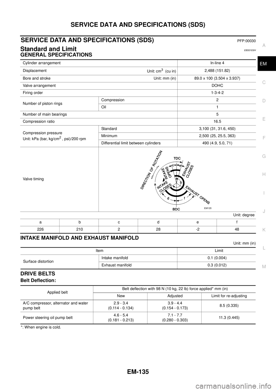
SERVICE DATA AND SPECIFICATIONS (SDS)PFP:00030
Standard and LimitEBS01E6H
GENERAL SPECIFICATIONS
INTAKE MANIFOLD AND EXHAUST MANIFOLD
Unit: mm (in)
DRIVE BELTS
Belt Deflection:
*: When engine is cold.Cylinder arrangementIn-line 4
Displacement
Unit: cm
3(cu in)2,488 (151.82)
Bore and stroke Unit: mm (in) 89.0 x 100 (3.504 x 3.937)
Valve arrangementDOHC
Firing order1-3-4-2
Number of piston ringsCompression 2
Oil 1
Number of main bearings5
Compression ratio16.5
Compression pressure
Unit: kPa (bar, kg/cm
2, psi)/200 rpmStandard 3,100 (31, 31.6, 450)
Minimum 2,500 (25, 25.5, 363)
Differential limit between cylinders 490 (4.9, 5.0, 71)
Valve timing
Unit: degree
abc de f
226 210 2 28 -2 48
EM120
Item Limit
Surface distortionIntake manifold 0.1 (0.004)
Exhaust manifold 0.3 (0.012)
Applied beltBelt deflection with 98 N (10 kg, 22 lb) force applied* mm (in)
New Adjusted Limit for re-adjusting
A/C compressor, alternator and water
pump belt2.9 - 3.4
(0.114 - 0.134)3.9 - 4.4
(0.154 - 0.173)8.5 (0.335)
Power steering oil pump belt4.6 - 5.4
(0.181 - 0.213)7.1 - 7.7
(0.280 - 0.303)11.3 (0.445)
Page 1535 of 3171
PREPARATION
FAX-3
C
E
F
G
H
I
J
K
L
MA
B
FA X
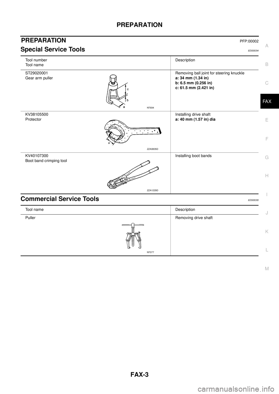
PREPARATIONPFP:00002
Special Service ToolsEDS003I4
Commercial Service ToolsEDS003I5
Tool number
Tool nameDescription
ST29020001
Gear arm pullerRemoving ball joint for steering knuckle
a: 34 mm (1.34 in)
b: 6.5 mm (0.256 in)
c: 61.5 mm (2.421 in)
KV38105500
ProtectorInstalling drive shaft
a: 40 mm (1.57 in) dia
KV40107300
BootbandcrimpingtoolInstalling boot bands
NT694
ZZA0835D
ZZA1229D
Tool nameDescription
PullerRemoving drive shaft
NT077