Page 1189 of 3171
DTC P0580, P0581 ASCD STEERING SWITCH
EC-209
C
D
E
F
G
H
I
J
K
L
MA
EC
Diagnostic ProcedureEBS01KIA
1.CHECK GROUND CONNECTIONS
1. Turn ignition switch OFF.
2. Loosen and retighten three ground screws on the body.
Refer toEC-78, "
Ground Inspection".
OK or NG
OK >> GO TO 2.
NG >> Repair or replace ground connections.
: Vehicle front
1. Body ground E21 2. ECM 3. Body ground E41
4. A/C high-pressure service valve 5. ABS actuator and electric unit
(control unit)6. Body ground E61
MBIB1218E
Page 1190 of 3171

EC-210
DTC P0580, P0581 ASCD STEERING SWITCH
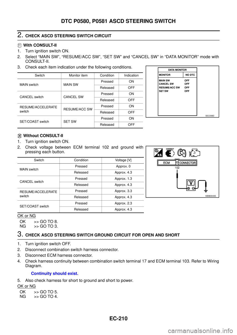
2.CHECK ASCD STEERING SWITCH CIRCUIT
With CONSULT-II
1. Turn ignition switch ON.
2. Select “MAIN SW”, “RESUME/ACC SW”, “SET SW” and “CANCEL SW” in “DATA MONITOR” mode with
CONSULT-II.
3. Check each item indication under the following conditions.
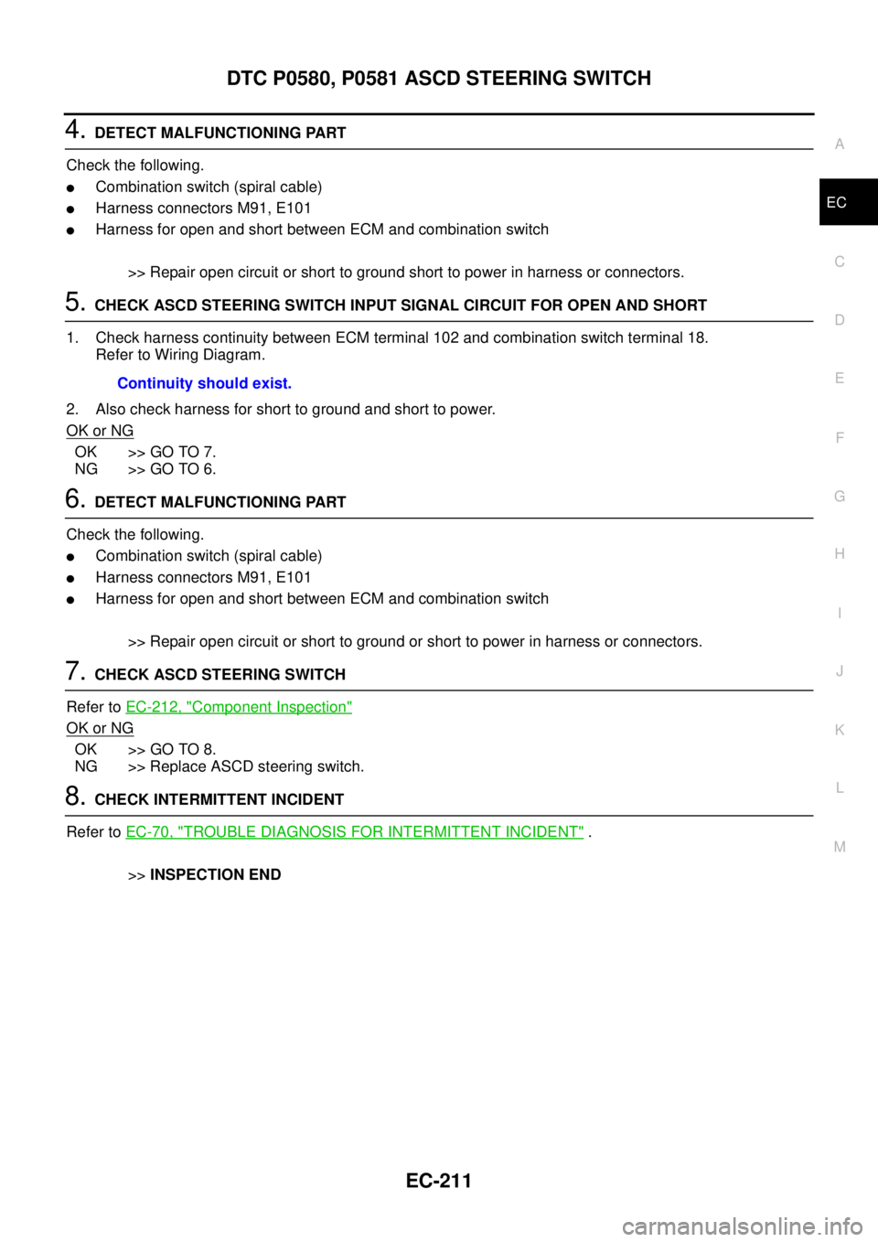
Without CONSULT-II
1. Turn ignition switch ON.
2. Check voltage between ECM terminal 102 and ground with
pressing each button.
OK or NG
OK >> GO TO 8.
NG >> GO TO 3.
3.CHECK ASCD STEERING SWITCH GROUND CIRCUIT FOR OPEN AND SHORT
1. Turn ignition switch OFF.
2. Disconnect combination switch harness connector.
3. Disconnect ECM harness connector.
4. Check harness continuity between combination switch terminal 17 and ECM terminal 103. Refer to Wiring
Diagram.
5. Also check harness for short to ground and short to power.
OK or NG
OK >> GO TO 5.
NG >> GO TO 4.
Switch Monitor item Condition Indication
MAIN switch MAIN SWPressed ON
Released OFF
CANCEL switch CANCEL SWPressed ON
Released OFF
RESUME/ACCELERATE
switchRESUME/ACC SWPressed ON
Released OFF
SET/COAST switch SET SWPressed ON
Released OFF
SEC006D
Switch Condition Voltage [V]
MAIN switchPressed Approx. 0
Released Approx. 4.3
CANCEL switchPressed Approx. 1.3
Released Approx. 4.3
RESUME/ACCELERATE
switchPressed Approx. 3.3
Released Approx. 4.3
SET/COAST switchPressed Approx. 2.3
Released Approx. 4.3
MBIB0043E
Continuity should exist.
Page 1191 of 3171

DTC P0580, P0581 ASCD STEERING SWITCH
EC-211
C
D
E
F
G
H
I
J
K
L
MA
EC
4.DETECT MALFUNCTIONING PART
Check the following.
lCombination switch (spiral cable)
lHarness connectors M91, E101
lHarness for open and short between ECM and combination switch
>> Repair open circuit or short to ground short to power in harness or connectors.
5.CHECK ASCD STEERING SWITCH INPUT SIGNAL CIRCUIT FOR OPEN AND SHORT
1. Check harness continuity between ECM terminal 102 and combination switch terminal 18.
Refer to Wiring Diagram.
2. Also check harness for short to ground and short to power.
OK or NG
OK >> GO TO 7.
NG >> GO TO 6.
6.DETECT MALFUNCTIONING PART
Check the following.
lCombination switch (spiral cable)
lHarness connectors M91, E101
lHarness for open and short between ECM and combination switch
>> Repair open circuit or short to ground or short to power in harness or connectors.
7.CHECK ASCD STEERING SWITCH
Refer toEC-212, "
Component Inspection"
OK or NG
OK >> GO TO 8.
NG >> Replace ASCD steering switch.
8.CHECK INTERMITTENT INCIDENT
Refer toEC-70, "
TROUBLE DIAGNOSIS FOR INTERMITTENT INCIDENT".
>>INSPECTION END Continuity should exist.
Page 1192 of 3171
EC-212
DTC P0580, P0581 ASCD STEERING SWITCH
Component Inspection
EBS01KIB
ASCD STEERING SWITCH
1. Disconnect combination switch.
2. Check continuity between combination switch terminals 17 and
18 with pushing each switch.
Switch Condition Resistance [W]
MAIN switchPressed Approx. 0
Released Approx. 4,000
CANCEL switchPressed Approx. 250
Released Approx. 4,000
RESUME/ACCELERATE
switchPressed Approx. 1,480
Released Approx. 4,000
SET/COAST switchPressed Approx. 660
Released Approx. 4,000
MBIB1252E
Page 1331 of 3171
ASCD INDICATOR
EC-351
C
D
E
F
G
H
I
J
K
L
MA
EC
ASCD INDICATORPFP:24814
Component DescriptionEBS01KMY
ASCD indicator lamp illuminates to indicate ASCD operation status. Lamp has two indicators, CRUISE and
SET, and is integrated in combination meter.
CRUISE indicator illuminates when MAIN switch on ASCD steering switch is turned ON to indicated that
ASCD system is ready for operation.
SET indicator illuminates when following conditions are met.
lCRUISE indicator is illuminated.
lSET/COAST switch on ASCD steering switch is turned ON while vehicle speed is within the range of
ASCD setting.
SET indicator remains lit during ASCD control.
Refer toEC-355, "
AUTOMATIC SPEED CONTROL DEVICE (ASCD)"for the ASCD function.
Page 1335 of 3171

AUTOMATIC SPEED CONTROL DEVICE (ASCD)
EC-355
C
D
E
F
G
H
I
J
K
L
MA
EC
AUTOMATIC SPEED CONTROL DEVICE (ASCD)PFP:18930
System DescriptionEBS01KN2
INPUT/OUTPUT SIGNAL CHART
*: This signal is sent to the ECM through CAN communication line.
BASIC ASCD SYSTEM
Refer to Owner's Manual for ASCD operating instructions.
Automatic Speed Control Device (ASCD) allows a driver to keep vehicle at predetermined constant speed
without depressing accelerator pedal. Driver can set vehicle speed in advance between approximately 40 km/
h(25MPH)and185km/h(115MPH).
ECM controls fuel injection value to regulate engine speed.
Operation status of ASCD is indicated by CRUISE indicator and SET indicator in combination meter. If any
malfunction occurs in ASCD system, it automatically deactivates control.
SET OPERATION
Press ASCD MAIN switch. (The CRUISE indicator in combination meter illuminates.)
When vehicle speed reaches a desired speed between approximately 40 km/h (25 MPH) and 185 km/h (115
MPH), press SET/COST switch. (Then SET indicator in combination meter illuminates.)
ACCEL OPERATION
If the RESUME/ACCELERATE switch is depressed during cruise control driving, increase the vehicle speed
until the switch is released or vehicle speed reaches maximum speed controlled by the system.
And then ASCD will keep the new set speed.
CANCEL OPERATION
When any of following conditions exist, cruise operation will be canceled.
lCANCEL switch is depressed
lMore than 2 switches at ASCD steering switch are depressed at the same time (Set speed will be cleared)
lBrake pedal is depressed
lClutch pedal is depressed or gear position is changed to the neutral position (M/T models)
lSelector lever is changed to N, P, R position (A/T models)
lVehicle speed decreased to 13 km/h (8 MPH) lower than the set speed
When the ECM detects any of the following conditions, the ECM will cancel the cruise operation and inform
the driver by blinking indicator lamp.
lMalfunction for some self-diagnoses regarding ASCD control: SET lamp will blink quickly.
If MAIN switch is turned to OFF during ASCD is activated, all of ASCD operations will be canceled and vehicle
speed memory will be erased.
COAST OPERATION
When the SET/COAST switch is depressed during cruise control driving, decrease vehicle set speed until the
switch is released. And then ASCD will keep the new set speed.
RESUME OPERATION
When the RESUME/ACCELERATE switch is depressed after cancel operation other than depressing MAIN
switch is performed, vehicle speed will return to last set speed. To resume vehicle set speed, vehicle condition
must meet following conditions.
Sensor Input signal to ECM ECM function Actuator
ASCD brake switch Brake pedal operation
ASCD vehicle speed control Fuel injector and Fuel pump Stop lamp switch Brake pedal operation
ASCD clutch switch (M/T) Clutch pedal operation
ASCD steering switch ASCD steering switch operation
Park/Neutral position (PNP)
switchGear position
Combination meter* Vehicle speed
TCM* Powertrain revolution
Page 1336 of 3171
EC-356
AUTOMATIC SPEED CONTROL DEVICE (ASCD)
lBrake pedal is released
lClutch pedal is released (M/T models)
lSelector lever is in other than P and N positions (A/T models)
lVehicle speed is greater than 40 km/h (25 MPH) and less than 185 km/h (115 MPH)
Component DescriptionEBS01KN3
ASCD STEERING SWITCH
Refer toEC-206.
ASCD BRAKE SWITCH
Refer toEC-189andEC-330.
ASCD CLUTCH SWITCH
Refer toEC-189andEC-330.
STOP LAMP SWITCH
Refer toEC-189andEC-330.
ASCD INDICATOR
Refer toEC-351.
Page 1337 of 3171

SERVICE DATA AND SPECIFICATIONS (SDS)
EC-357
C
D
E
F
G
H
I
J
K
L
MA
EC
SERVICE DATA AND SPECIFICATIONS (SDS)PFP:00100
General SpecificationsEBS01KN4
*: Under the following conditions:
lHeat up switch: OFF
lAir conditioner switch: OFF
lElectric load: OFF (Lights, heater fan & rear window defogger)
lSteering wheel: Kept in straight-ahead position
Mass Air Flow SensorEBS01KN5
*: Engine is warmed up to normal operating temperature and running under no load.
Intake Air Temperature SensorEBS01KN6
Engine Coolant Temperature SensorEBS01KN7
Fuel Rail Pressure SensorEBS01KN8
Fuel InjectorEBS01KN9
Glow PlugEBS01KNA
EGR Volume Control ValveEBS01KNB
Crankshaft Position SensorEBS01KNC
Refer toEC-164, "Component Inspection".
Camshaft Position SensorEBS01KND
Refer toEC-175, "Component Inspection".
Target idle speedA/T No load* (in P or N position)
750±25 rpm
M/T No load* (in Neutral position)
Air conditioner: ONA/T In P or N position 750 rpm or more
M/T In Neutral position 800 rpm or more
Maximum engine speed4,900 rpm
Supply voltageBattery voltage (11 - 14V)
Ignition switch ON (Engine stopped.) Approx. 0.4V
Idle (Engine is warmed up to normal operating temperature.) 1.3 - 1.7V *
Temperature°C(°F) Resistance kW
25 (77)1.800 - 2.200
80 (176)0.283 - 0.359
Temperature°C(°F) Resistance kW
20 (68)2.1 - 2.9
50 (122)0.68 - 1.00
90 (194)0.236 - 0.260
Supply voltageApproximately 5V
Idle (Engine is warmed up to normal operating temperature.) 1.7 - 2.0V
2,000 rpm (Engine is warmed up to normal operating tempera-
ture.)2.0 - 2.3V
Resistance [at 10 - 60°C (50 - 140°F)] 0.2 - 0.8W
Resistance [at 25°C(77°F)] Approximately 0.8W
Resistance [at 25°C(77°F)] 13 - 17W