Page 1536 of 3171
FAX-4
NOISE, VIBRATION, AND HARSHNESS (NVH) TROUBLESHOOTING
NOISE, VIBRATION, AND HARSHNESS (NVH) TROUBLESHOOTING
PFP:00003
NVH Troubleshooting ChartEDS003I6
Use the chart below to help you find the cause of the symptom. If necessary, repair or replace these parts.
´: ApplicableReference page
FAX-14FAX-7FAX-5FAX-5FAX-7FAX-5
PR-2, "
NVH Troubleshooting Chart
"
FFD-6, "
NVH Troubleshooting Chart
"
FSU-5, "
NVH Troubleshooting Chart
"
WT-2, "
NVH Troubleshooting Chart
"
WT-2, "
NVH Troubleshooting Chart
"
BR-5, "
NVH Troubleshooting Chart
"
PS-5, "
NVH Troubleshooting Chart
"
Possible cause and SUSPECTED PARTS
Excessive joint angle
Joint sliding resistance
Imbalance
Improper installation, looseness
Parts interference
Wheel bearing damage
PROPELLER SHAFT
FRONT FINAL DRIVE
SUSPENSION
TIRES
ROAD WHEEL
BRAKES
STEERING
SymptomNoise´´ ´´ ´´´´´´´
Shake´ ´´´ ´ ´´´´´
Vibration´´´´´ ´ ´´ ´
Shimmy´ ´´ ´´´´´
Shudder´´´´ ´´´´´
Poor quality ride or
handling´´´ ´´´
Page 1537 of 3171
WHEEL HUB
FAX-5
C
E
F
G
H
I
J
K
L
MA
B
FA X
WHEEL HUBPFP:43202
On-Vehicle Inspection and ServiceEDS003I7
Make sure the mounting conditions (looseness, backlash) of each component and component status (wear,
damage) are normal.
WHEEL BEARING INSPECTION
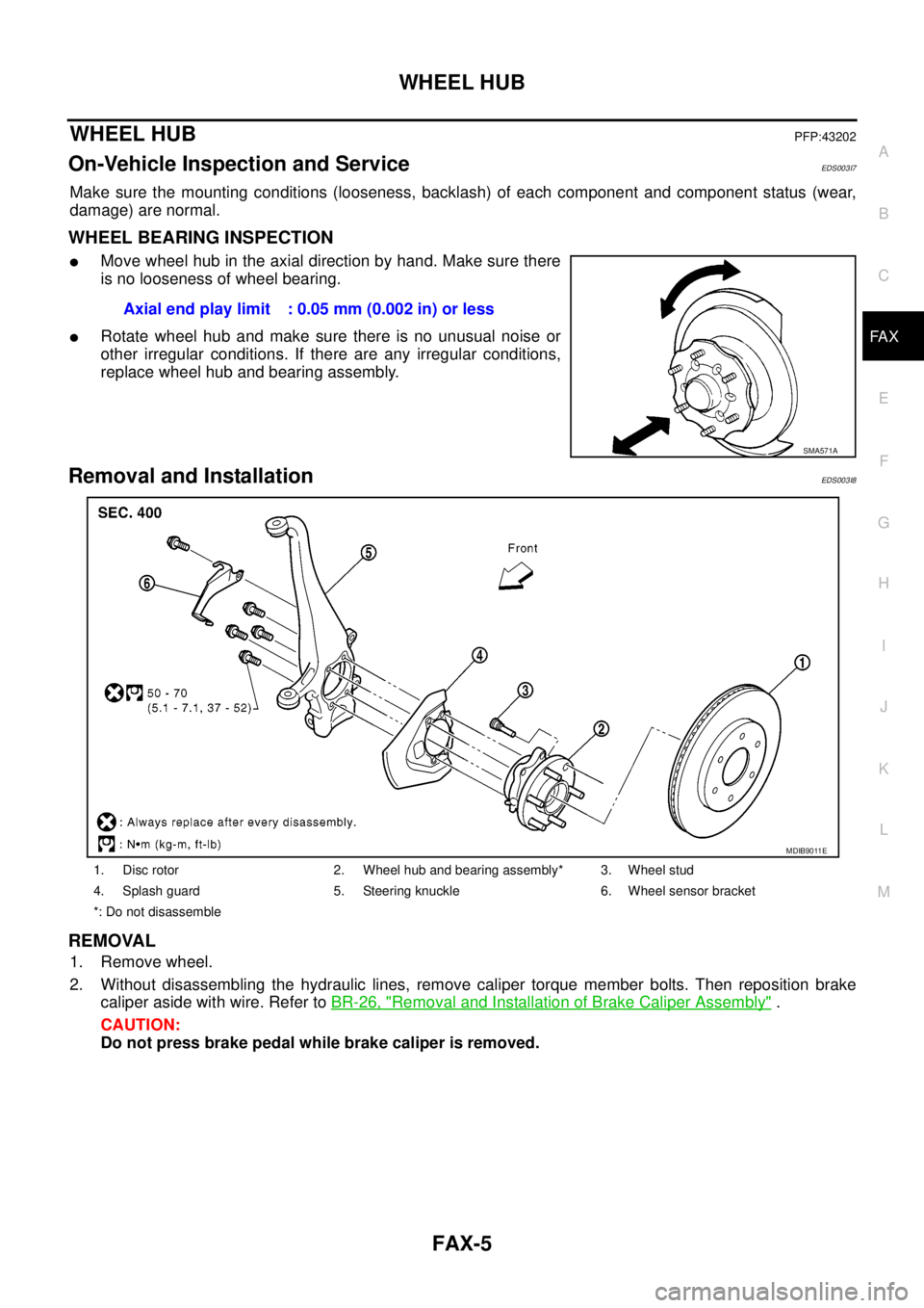
lMove wheel hub in the axial direction by hand. Make sure there
is no looseness of wheel bearing.
lRotate wheel hub and make sure there is no unusual noise or
other irregular conditions. If there are any irregular conditions,
replace wheel hub and bearing assembly.
Removal and InstallationEDS003I8
REMOVAL
1. Remove wheel.
2. Without disassembling the hydraulic lines, remove caliper torque member bolts. Then reposition brake
caliper aside with wire. Refer toBR-26, "
Removal and Installation of Brake Caliper Assembly".
CAUTION:
Do not press brake pedal while brake caliper is removed.Axial end play limit : 0.05 mm (0.002 in) or less
SMA571A
1. Disc rotor 2. Wheel hub and bearing assembly* 3. Wheel stud
4. Splash guard 5. Steering knuckle 6. Wheel sensor bracket
*: Do not disassemble
MDIB9011E
Page 1538 of 3171
FAX-6
WHEEL HUB
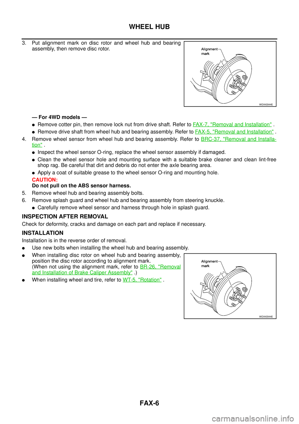
3. Put alignment mark on disc rotor and wheel hub and bearing
assembly, then remove disc rotor.
— For 4WD models —
lRemove cotter pin, then remove lock nut from drive shaft. Refer toFA X - 7 , "Removal and Installation".
lRemove drive shaft from wheel hub and bearing assembly. Refer toFAX-5, "Removal and Installation".
4. Remove wheel sensor from wheel hub and bearing assembly. Refer toBRC-37, "
Removal and Installa-
tion".
lInspect the wheel sensor O-ring, replace the wheel sensor assembly if damaged.
lClean the wheel sensor hole and mounting surface with a suitable brake cleaner and clean lint-free
shop rag. Be careful that dirt and debris do not enter the axle bearing area.
lApply a coat of suitable grease to the wheel sensor O-ring and mounting hole.
CAUTION:
Do not pull on the ABS sensor harness.
5. Remove wheel hub and bearing assembly bolts.
6. Remove splash guard and wheel hub and bearing assembly from steering knuckle.
lCarefully remove wheel sensor and harness through hole in splash guard.
INSPECTION AFTER REMOVAL
Check for deformity, cracks and damage on each part and replace if necessary.
INSTALLATION
Installation is in the reverse order of removal.
lUse new bolts when installing the wheel hub and bearing assembly.
lWhen installing disc rotor on wheel hub and bearing assembly,
position the disc rotor according to alignment mark.
(When not using the alignment mark, refer toBR-26, "
Removal
and Installation of Brake Caliper Assembly".)
lWhen installing wheel and tire, refer toWT-5, "Rotation".
WDIA0044E
WDIA0044E
Page 1539 of 3171
DRIVE SHAFT
FAX-7
C
E
F
G
H
I
J
K
L
MA
B
FA X
DRIVE SHAFTPFP:39100
Removal and InstallationEDS003I9
REMOVAL
1. Remove wheel.
2. Remove ABS sensor harness from mount on knuckle, then disconnect ABS sensor harness connector.
CAUTION:
Do not pull on ABS sensor harness.
3. Remove steering knuckle. Refer toFSU-16, "
Removal and Installation".
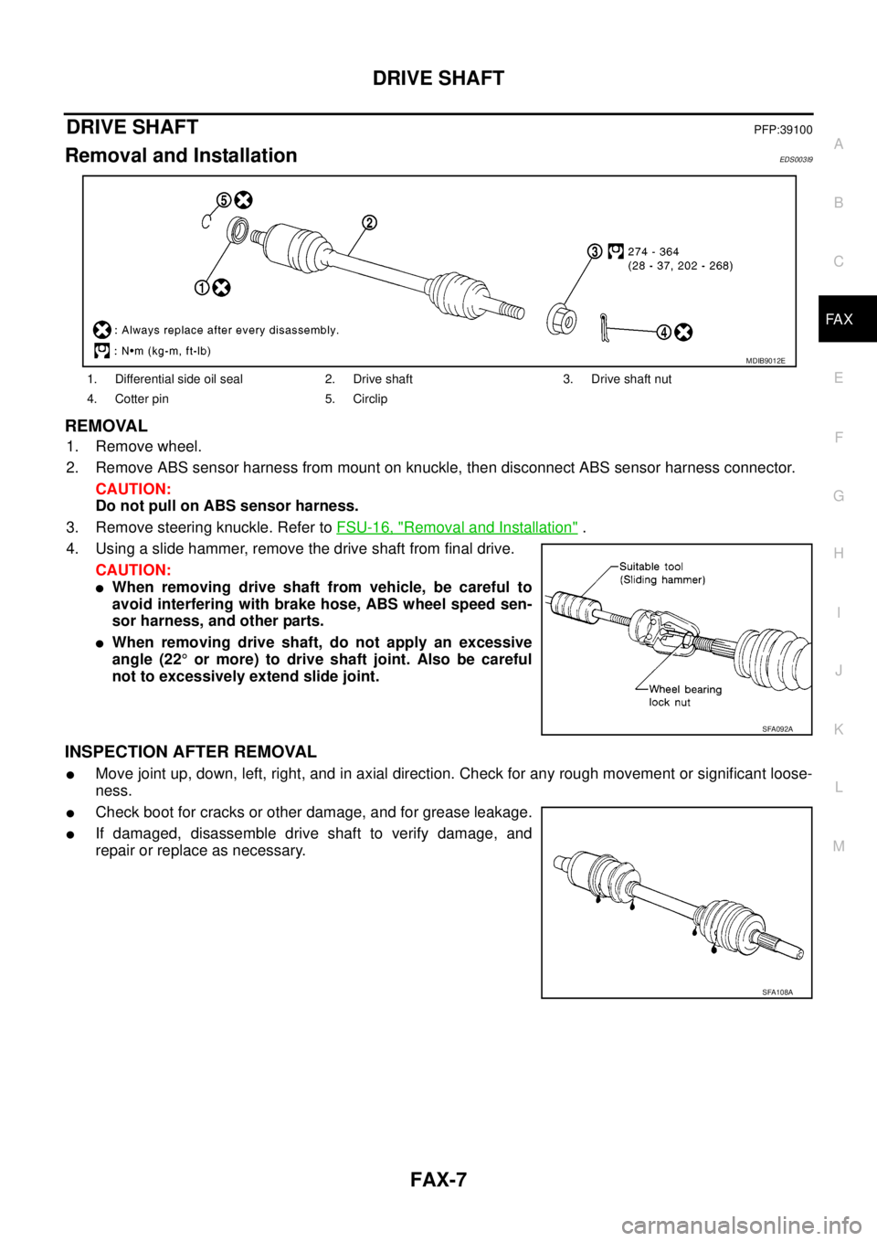
4. Using a slide hammer, remove the drive shaft from final drive.
CAUTION:
lWhen removing drive shaft from vehicle, be careful to
avoid interfering with brake hose, ABS wheel speed sen-
sor harness, and other parts.
lWhen removing drive shaft, do not apply an excessive
angle (22°or more) to drive shaft joint. Also be careful
not to excessively extend slide joint.
INSPECTION AFTER REMOVAL
lMove joint up, down, left, right, and in axial direction. Check for any rough movement or significant loose-
ness.
lCheck boot for cracks or other damage, and for grease leakage.
lIf damaged, disassemble drive shaft to verify damage, and
repair or replace as necessary.
1. Differential side oil seal 2. Drive shaft 3. Drive shaft nut
4. Cotter pin 5. Circlip
MDIB9012E
SFA092A
SFA108A
Page 1552 of 3171
FFD-6
NOISE, VIBRATION AND HARSHNESS (NVH) TROUBLESHOOTING
NOISE, VIBRATION AND HARSHNESS (NVH) TROUBLESHOOTING
PFP:00003
NVH Troubleshooting ChartEDS0034Z
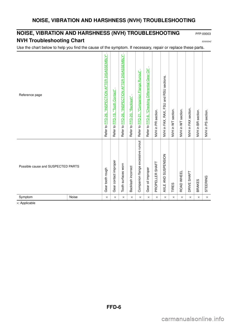
Use the chart below to help you find the cause of the symptom. If necessary, repair or replace these parts.
´: ApplicableReference page
Refer toFFD-26, "
INSPECTION AFTER DISASSEMBLY
".
Refer toFFD-19, "
To o t h C o n t a c t
".
Refer toFFD-26, "
INSPECTION AFTER DISASSEMBLY
".
Refer toFFD-20, "
Backlash
".
Refer toFFD-21, "
Companion Flange Runout
".
Refer toFFD-8, "
Checking Differential Gear Oil
".
NVH in PR section.
NVH in FAX, RAX, FSU and RSU sections.
NVH in WT section.
NVH in WT section.
NVH in FAX section.
NVH in BR section.
NVH in PS section.
Possible cause and SUSPECTED PARTS
Gear tooth rough
Gear contact improper
Tooth surfaces worn
Backlash incorrect
Companion flange excessive runout
Gear oil improper
PROPELLER SHAFT
AXLE AND SUSPENSION
TIRES
ROAD WHEEL
DRIVE SHAFT
BRAKES
STEERING
Symptom Noise´´´´´´´´´´´´´
Page 1556 of 3171
FFD-10
FRONT OIL SEAL
CAUTION:
Do not pull on the ABS sensor harness.
6. Support the lower link using a suitable jack.
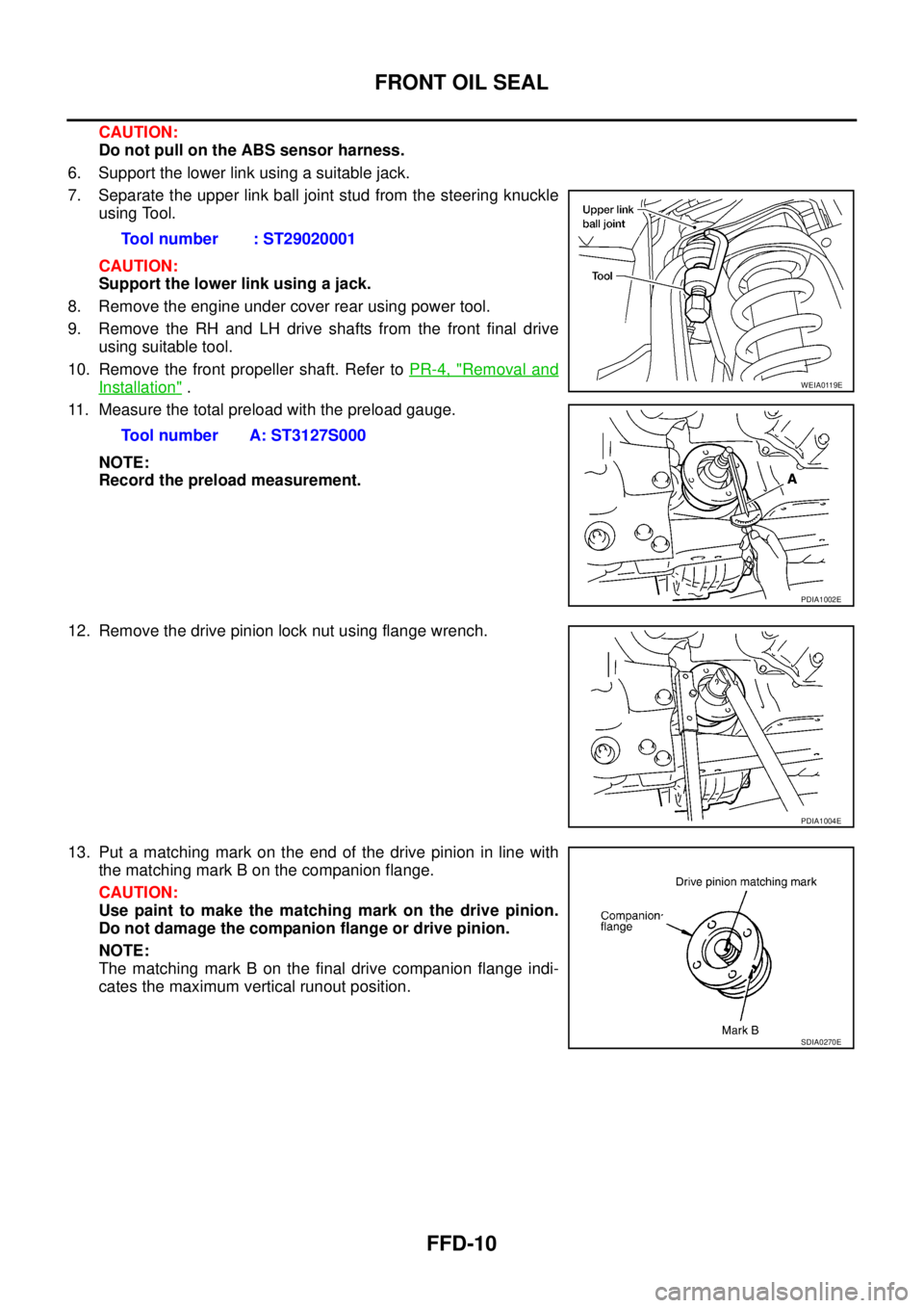
7. Separate the upper link ball joint stud from the steering knuckle
using Tool.
CAUTION:
Support the lower link using a jack.
8. Remove the engine under cover rear using power tool.
9. Remove the RH and LH drive shafts from the front final drive
using suitable tool.
10. Remove the front propeller shaft. Refer toPR-4, "
Removal and
Installation".
11. Measure the total preload with the preload gauge.
NOTE:
Record the preload measurement.
12. Remove the drive pinion lock nut using flange wrench.
13. Put a matching mark on the end of the drive pinion in line with
the matching mark B on the companion flange.
CAUTION:
Use paint to make the matching mark on the drive pinion.
Do not damage the companion flange or drive pinion.
NOTE:
The matching mark B on the final drive companion flange indi-
cates the maximum vertical runout position.Tool number : ST29020001
Tool number A: ST3127S000WEIA0119E
PDIA1002E
PDIA1004E
SDIA0270E
Page 1559 of 3171
SIDE OIL SEAL
FFD-13
C
E
F
G
H
I
J
K
L
MA
B
FFD
SIDE OIL SEALPFP:33142
Removal and InstallationEDS00354
REMOVAL
1. Remove the front wheels and tires using power tool.
2. Without disassembling the hydraulic lines, remove the caliper torque member bolts using power tool.
Then reposition the brake caliper aside using suitable wire. Refer toBR-26, "
Removal and Installation of
Brake Caliper Assembly".
CAUTION:
Do not press the brake pedal while brake caliper is removed.
3. Remove the ABS sensor harness from the mount on the knuckle.
CAUTION:
Do not pull on the ABS sensor harness.
4. Support the lower link using a suitable jack.
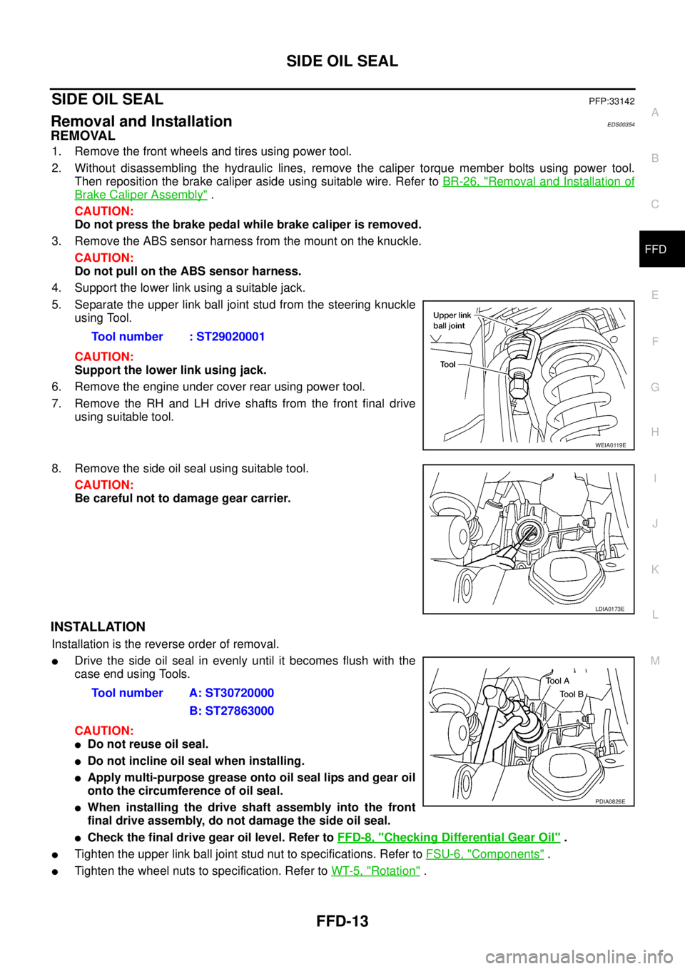
5. Separate the upper link ball joint stud from the steering knuckle
using Tool.
CAUTION:
Support the lower link using jack.
6. Remove the engine under cover rear using power tool.
7. Remove the RH and LH drive shafts from the front final drive
using suitable tool.
8. Remove the side oil seal using suitable tool.
CAUTION:
Be careful not to damage gear carrier.
INSTALLATION
Installation is the reverse order of removal.
lDrive the side oil seal in evenly until it becomes flush with the
case end using Tools.
CAUTION:
lDo not reuse oil seal.
lDo not incline oil seal when installing.
lApply multi-purpose grease onto oil seal lips and gear oil
onto the circumference of oil seal.
lWhen installing the drive shaft assembly into the front
final drive assembly, do not damage the side oil seal.
lCheck the final drive gear oil level. Refer toFFD-8, "Checking Differential Gear Oil".
lTighten the upper link ball joint stud nut to specifications. Refer toFSU-6, "Components".
lTighten the wheel nuts to specification. Refer toWT-5, "Rotation". Tool number : ST29020001
WEIA0119E
LDIA0173E
Tool number A: ST30720000
B: ST27863000
PDIA0826E
Page 1562 of 3171
FFD-16
FRONT FINAL DRIVE ASSEMBLY
CAUTION:
Do not pull on the ABS sensor harness.
4. Support the lower link using a suitable jack.
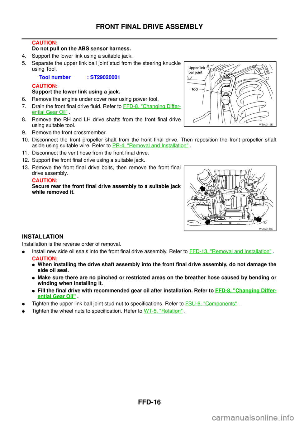
5. Separate the upper link ball joint stud from the steering knuckle
using Tool.
CAUTION:
Support the lower link using a jack.
6. Remove the engine under cover rear using power tool.
7. Drain the front final drive fluid. Refer toFFD-8, "
Changing Differ-
ential Gear Oil".
8. Remove the RH and LH drive shafts from the front final drive
using suitable tool.
9. Remove the front crossmember.
10. Disconnect the front propeller shaft from the front final drive. Then reposition the front propeller shaft
aside using suitable wire. Refer toPR-4, "
Removal and Installation".
11. Disconnect the vent hose from the front final drive.
12. Support the front final drive using a suitable jack.
13. Remove the front final drive bolts, then remove the front final
drive assembly.
CAUTION:
Secure rear the front final drive assembly to a suitable jack
while removed it.
INSTALLATION
Installation is the reverse order of removal.
lInstall new side oil seals into the front final drive assembly. Refer toFFD-13, "Removal and Installation".
CAUTION:
lWhen installing the drive shaft assembly into the front final drive assembly, do not damage the
side oil seal.
lMake sure there are no pinched or restricted areas on the breather hose caused by bending or
winding when installing it.
lFill the final drive with recommended gear oil after installation. Refer toFFD-8, "Changing Differ-
ential Gear Oil".
lTighten the upper link ball joint stud nut to specifications. Refer toFSU-6, "Components".
lTighten the wheel nuts to specification. Refer toWT-5, "Rotation". Tool number : ST29020001
WEIA0119E
WDIA0145E