2005 NISSAN NAVARA steering
[x] Cancel search: steeringPage 1754 of 3171
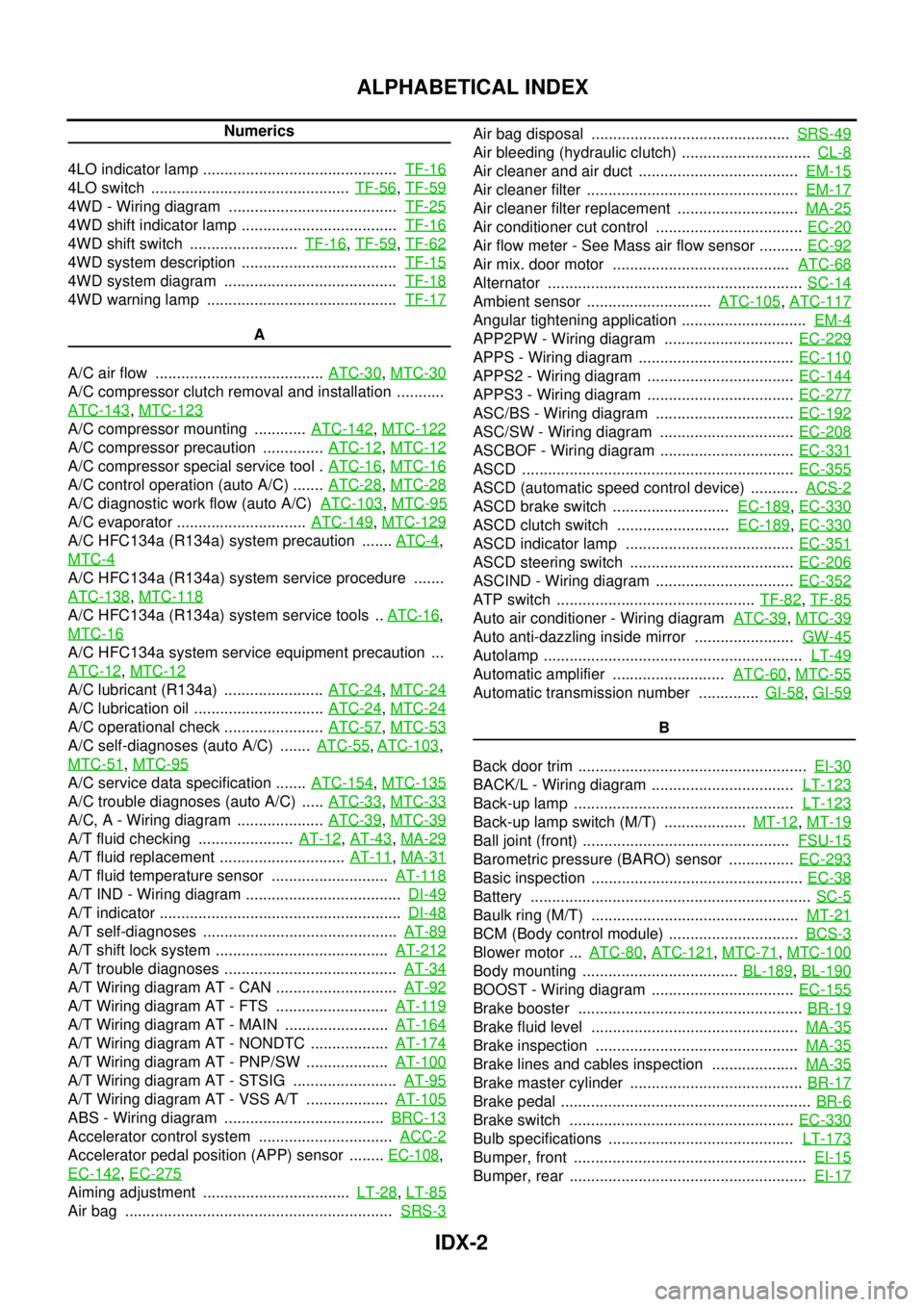
IDX-2
ALPHABETICAL INDEX
Numerics
4LO indicator lamp .............................................TF-16
4LO switch ..............................................TF-56,TF-59
4WD - Wiring diagram .......................................TF-25
4WD shift indicator lamp ....................................TF-16
4WD shift switch .........................TF-16,TF-59,TF-62
4WD system description ....................................TF-15
4WD system diagram ........................................TF-18
4WD warning lamp ............................................TF-17
A
A/C air flow .......................................ATC-30
,MTC-30
A/C compressor clutch removal and installation ...........
ATC-143
,MTC-123
A/C compressor mounting ............ATC-142,MTC-122
A/C compressor precaution ..............ATC-12,MTC-12
A/C compressor special service tool .ATC-16,MTC-16
A/C control operation (auto A/C) .......ATC-28,MTC-28
A/C diagnostic work flow (auto A/C)ATC-103,MTC-95
A/C evaporator ..............................ATC-149,MTC-129
A/C HFC134a (R134a) system precaution .......ATC-4,
MTC-4
A/C HFC134a (R134a) system service procedure .......
ATC-138
,MTC-118
A/C HFC134a (R134a) system service tools ..ATC-16,
MTC-16
A/C HFC134a system service equipment precaution ...
ATC-12
,MTC-12
A/C lubricant (R134a) .......................ATC-24,MTC-24
A/C lubrication oil ..............................ATC-24,MTC-24
A/C operational check .......................ATC-57,MTC-53
A/C self-diagnoses (auto A/C) .......ATC-55,ATC-103,
MTC-51
,MTC-95
A/C service data specification .......ATC-154,MTC-135
A/C trouble diagnoses (auto A/C) .....ATC-33,MTC-33
A/C, A - Wiring diagram ....................ATC-39,MTC-39
A/T fluid checking ......................AT-12,AT-43,MA-29
A/T fluid replacement .............................AT-11,MA-31
A/T fluid temperature sensor ...........................AT-118
A/T IND - Wiring diagram ....................................DI-49
A/T indicator ........................................................DI-48
A/T self-diagnoses .............................................AT-89
A/T shift lock system ........................................AT-212
A/T trouble diagnoses ........................................AT-34
A/T Wiring diagram AT - CAN ............................AT-92
A/T Wiring diagram AT - FTS ..........................AT-119
A/T Wiring diagram AT - MAIN ........................AT-164
A/T Wiring diagram AT - NONDTC ..................AT-174
A/T Wiring diagram AT - PNP/SW ...................AT-100
A/T Wiring diagram AT - STSIG ........................AT-95
A/T Wiring diagram AT - VSS A/T ...................AT-105
ABS - Wiring diagram .....................................BRC-13
Accelerator control system ...............................ACC-2
Accelerator pedal position (APP) sensor ........EC-108,
EC-142
,EC-275
Aiming adjustment ..................................LT-28,LT-85
Air bag ..............................................................SRS-3
Air bag disposal ..............................................SRS-49
Air bleeding (hydraulic clutch) ..............................CL-8
Air cleaner and air duct .....................................EM-15
Air cleaner filter .................................................EM-17
Air cleaner filter replacement ............................MA-25
Air conditioner cut control ..................................EC-20
Air flow meter - See Mass air flow sensor ..........EC-92
Air mix. door motor .........................................ATC-68
Alternator ...........................................................SC-14
Ambient sensor .............................ATC-105,ATC-117
Angular tightening application .............................EM-4
APP2PW - Wiring diagram ..............................EC-229
APPS - Wiring diagram ....................................EC-110
APPS2 - Wiring diagram ..................................EC-144
APPS3 - Wiring diagram ..................................EC-277
ASC/BS - Wiring diagram ................................EC-192
ASC/SW - Wiring diagram ...............................EC-208
ASCBOF - Wiring diagram ...............................EC-331
ASCD ...............................................................EC-355
ASCD (automatic speed control device) ...........ACS-2
ASCD brake switch ...........................EC-189,EC-330
ASCD clutch switch ..........................EC-189,EC-330
ASCD indicator lamp .......................................EC-351
ASCD steering switch ......................................EC-206
ASCIND - Wiring diagram ................................EC-352
ATP switch ..............................................TF-82,TF-85
Auto air conditioner - Wiring diagramATC-39,MTC-39
Auto anti-dazzling inside mirror .......................GW-45
Autolamp ............................................................LT-49
Automatic amplifier ..........................ATC-60,MTC-55
Automatic transmission number ..............GI-58,GI-59
B
Back door trim .....................................................EI-30
BACK/L - Wiring diagram .................................LT-123
Back-up lamp ...................................................LT-123
Back-up lamp switch (M/T) ...................MT-12,MT-19
Ball joint (front) ................................................FSU-15
Barometric pressure (BARO) sensor ...............EC-293
Basic inspection .................................................EC-38
Battery .................................................................SC-5
Baulk ring (M/T) ................................................MT-21
BCM (Body control module) ..............................BCS-3
Blower motor ...ATC-80,ATC-121,MTC-71,MTC-100
Body mounting ....................................BL-189,BL-190
BOOST - Wiring diagram .................................EC-155
Brake booster ....................................................BR-19
Brake fluid level ................................................MA-35
Brake inspection ...............................................MA-35
Brake lines and cables inspection ....................MA-35
Brake master cylinder ........................................BR-17
Brake pedal ..........................................................BR-6
Brake switch ....................................................EC-330
Bulb specifications ...........................................LT-173
Bumper, front ......................................................EI-15
Bumper, rear .......................................................EI-17
Page 1758 of 3171
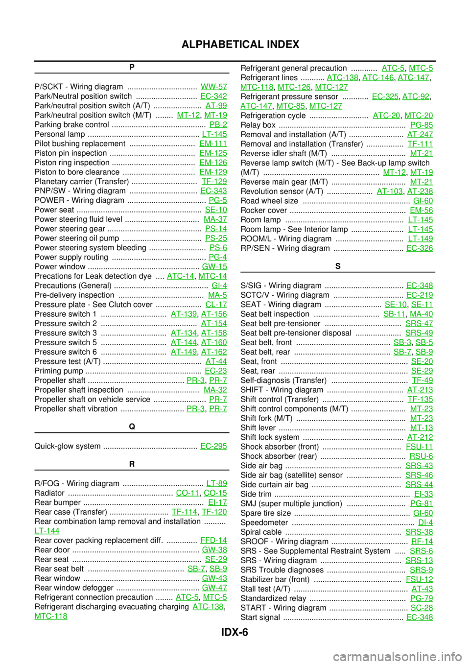
IDX-6
ALPHABETICAL INDEX
P
P/SCKT - Wiring diagram ................................WW-57
Park/Neutral position switch ............................EC-342
Park/neutral position switch (A/T) ......................AT-99
Park/neutral position switch (M/T) ........MT-12,MT-19
Parking brake control ...........................................PB-2
Personal lamp ...................................................LT-145
Pilot bushing replacement ..............................EM-111
Piston pin inspection .......................................EM-125
Piston ring inspection ......................................EM-126
Piston to bore clearance .................................EM-129
Planetary carrier (Transfer) ..............................TF-129
PNP/SW - Wiring diagram ...............................EC-343
POWER - Wiring diagram ....................................PG-5
Power seat .........................................................SE-10
Power steering fluid level ..................................MA-37
Power steering gear ...........................................PS-14
Power steering oil pump ....................................PS-25
Power steering system bleeding ..........................PS-6
Power supply routing ...........................................PG-4
Power window ...................................................GW-15
Precations for Leak detection dye ....ATC-14,MTC-14
Precautions (General) ...........................................GI-4
Pre-delivery inspection .......................................MA-5
Pressure plate - See Clutch cover .....................CL-17
Pressure switch 1 ..............................AT-139,AT-156
Pressure switch 2 ............................................AT-154
Pressure switch 3 ..............................AT-134,AT-158
Pressure switch 5 ..............................AT-144,AT-160
Pressure switch 6 ..............................AT-149,AT-162
Pressure test (A/T) .............................................AT-44
Priming pump .....................................................EC-23
Propeller shaft ............................................PR-3,PR-7
Propeller shaft inspection .................................MA-32
Propeller shaft on vehicle service ........................PR-7
Propeller shaft vibration .............................PR-3,PR-7
Q
Quick-glow system ...........................................EC-295
R
R/FOG - Wiring diagram .....................................LT-89
Radiator ................................................CO-11,CO-15
Rear bumper .......................................................EI-17
Rear case (Transfer) ...........................TF-114,TF-120
Rear combination lamp removal and installation ..........
LT-144
Rear cover packing replacement diff. ..............FFD-14
Rear door ..........................................................GW-38
Rear seat ...........................................................SE-29
Rear seat belt ............................................SB-7,SB-9
Rear window .....................................................GW-43
Rear window defogger ......................................GW-47
Refrigerant connection precaution ........ATC-5,MTC-5
Refrigerant discharging evacuating chargingATC-138,
MTC-118
Refrigerant general precaution ............ATC-5,MTC-5
Refrigerant lines ...........ATC-138,ATC-146,ATC-147,
MTC-118
,MTC-126,MTC-127
Refrigerant pressure sensor ............EC-325,ATC-92,
ATC-147
,MTC-85,MTC-127
Refrigeration cycle ...........................ATC-20,MTC-20
Relay box ..........................................................PG-85
Removal and installation (A/T) .........................AT-247
Removal and installation (Transfer) .................TF-111
Reverse idler shaft (M/T) ..................................MT-21
Reverse lamp switch (M/T) - See Back-up lamp switch
(M/T) .....................................................MT-12
,MT-19
Reverse main gear (M/T) ..................................MT-21
Revolution sensor (A/T) .....................AT-103,AT-238
Road wheel size .................................................GI-60
Rocker cover .....................................................EM-56
Room lamp ......................................................LT-145
Room lamp - See Interior lamp ........................LT-145
ROOM/L - Wiring diagram ...............................LT-149
RP/SEN - Wiring diagram ................................EC-326
S
S/SIG - Wiring diagram ....................................EC-348
SCTC/V - Wiring diagram ................................EC-219
SEAT - Wiring diagram ..........................SE-10,SE-11
Seat belt inspection ..............................SB-11,MA-40
Seat belt pre-tensioner ...................................SRS-47
Seat belt pre-tensioner disposal .....................SRS-49
Seat belt, front ...........................................SB-3,SB-5
Seat belt, rear ............................................SB-7,SB-9
Seat, front ..........................................................SE-20
Seat, rear ...........................................................SE-29
Self-diagnosis (Transfer) ...................................TF-49
SHIFT - Wiring diagram ...................................AT-213
Shift control (Transfer) .....................................TF-135
Shift control components (M/T) .........................MT-23
Shift fork (M/T) ..................................................MT-23
Shift lever ..........................................................MT-13
Shift lock system ..............................................AT-212
Shock absorber (front) ....................................FSU-11
Shock absorber (rear) .......................................RSU-6
Side air bag .....................................................SRS-43
Side air bag (satellite) sensor .........................SRS-46
Side curtain air bag .........................................SRS-44
Side trim ..............................................................EI-33
SMJ (super multiple junction) ...........................PG-81
Spare tire size .....................................................GI-60
Speedometer ........................................................DI-4
Spiral cable .....................................................SRS-38
SROOF - Wiring diagram ...................................RF-14
SRS - See Supplemental Restraint System .....SRS-6
SRS - Wiring diagram .....................................SRS-13
SRS Trouble diagnoses ....................................SRS-9
Stabilizer bar (front) ........................................FSU-12
Stall test (A/T) ....................................................AT-43
Standardized relay ............................................PG-79
START - Wiring diagram ....................................SC-28
Start signal .......................................................EC-348
Page 1759 of 3171
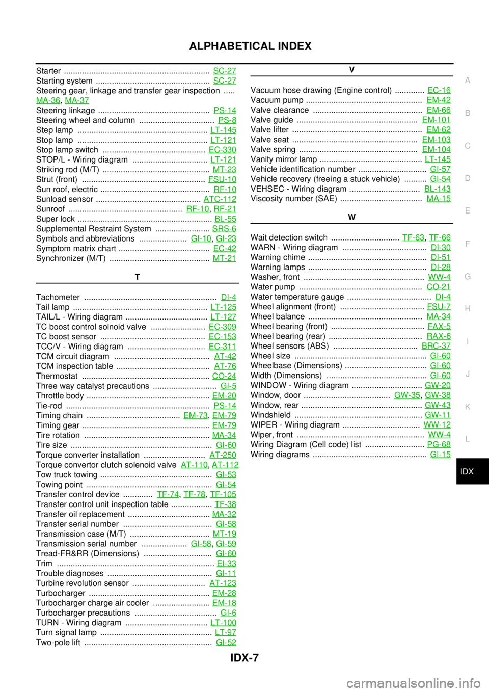
IDX-7
A
C
D
E
F
G
H
I
J
K
L B
IDX
ALPHABETICAL INDEX
Starter ................................................................SC-27
Starting system ..................................................SC-27
Steering gear, linkage and transfer gear inspection .....
MA-36
,MA-37
Steering linkage .................................................PS-14
Steering wheel and column .................................PS-8
Step lamp .........................................................LT-145
Stop lamp .........................................................LT-121
Stop lamp switch .............................................EC-330
STOP/L - Wiring diagram .................................LT-121
Striking rod (M/T) ...............................................MT-23
Strut (front) ......................................................FSU-10
Sun roof, electric ................................................RF-10
Sunload sensor ..............................................ATC-112
Sunroof ..................................................RF-10,RF-21
Super lock ...........................................................BL-55
Supplemental Restraint System ........................SRS-6
Symbols and abbreviations .....................GI-10,GI-23
Symptom matrix chart ........................................EC-42
Synchronizer (M/T) ............................................MT-21
T
Tachometer ..........................................................DI-4
Tail lamp ...........................................................LT-125
TAIL/L - Wiring diagram ....................................LT-127
TC boost control solnoid valve ........................EC-309
TC boost sensor ..............................................EC-153
TCC/V - Wiring diagram ..................................EC-311
TCM circuit diagram ..........................................AT-42
TCM inspection table .........................................AT-76
Thermostat ........................................................CO-24
Three way catalyst precautions ............................GI-5
Throttle body ......................................................EM-20
Tie-rod ...............................................................PS-14
Timing chain .........................................EM-73,EM-79
Timing gear ........................................................EM-79
Tire rotation .......................................................MA-34
Tire size ..............................................................GI-60
Torque converter installation ...........................AT-250
Torque convertor clutch solenoid valveAT-110,AT-112
Tow truck towing .................................................GI-53
Towing point .......................................................GI-54
Transfer control device .............TF-74,TF-78,TF-105
Transfer control unit inspection table ..................TF-38
Transfer oil replacement ....................................MA-32
Transfer serial number .......................................GI-58
Transmission case (M/T) ...................................MT-19
Transmission serial number ....................GI-58,GI-59
Tread-FR&RR (Dimensions) ..............................GI-60
Trim .....................................................................EI-33
Trouble diagnoses ..............................................GI-11
Turbine revolution sensor ................................AT-123
Turbocharger .....................................................EM-28
Turbocharger charge air cooler .........................EM-18
Turbocharger precautions ....................................GI-6
TURN - Wiring diagram ....................................LT-100
Turn signal lamp .................................................LT-97
Two-pole lift ........................................................GI-52
V
Vacuum hose drawing (Engine control) .............EC-16
Vacuum pump ...................................................EM-42
Valve clearance ................................................EM-66
Valve guide .....................................................EM-101
Valve lifter .........................................................EM-62
Valve seat .......................................................EM-103
Valve spring ....................................................EM-104
Vanity mirror lamp .............................................LT-145
Vehicle identification number ..............................GI-57
Vehicle recovery (freeing a stuck vehicle) ..........GI-54
VEHSEC - Wiring diagram ...............................BL-143
Viscosity number (SAE) ....................................MA-15
W
Wait detection switch ..............................TF-63
,TF-66
WARN - Wiring diagram .....................................DI-30
Warning chime ....................................................DI-51
Warning lamps ....................................................DI-28
Washer, front .....................................................WW-4
Water pump ......................................................CO-21
Water temperature gauge .....................................DI-4
Wheel alignment (front) .....................................FSU-7
Wheel balance ..................................................MA-34
Wheel bearing (front) .........................................FAX-5
Wheel bearing (rear) .........................................RAX-6
Wheel sensors (ABS) .....................................BRC-37
Wheel size ..........................................................GI-60
Wheelbase (Dimensions) ....................................GI-60
Width (Dimensions) ............................................GI-60
WINDOW - Wiring diagram ...............................GW-20
Window, door ......................................GW-35,GW-38
Window, rear .....................................................GW-43
Windshield ........................................................GW-11
WIPER - Wiring diagram ..................................WW-12
Wiper, front ........................................................WW-4
Wiring Diagram (Cell code) list ..........................PG-68
Wiring diagrams ..................................................GI-15
Page 1761 of 3171
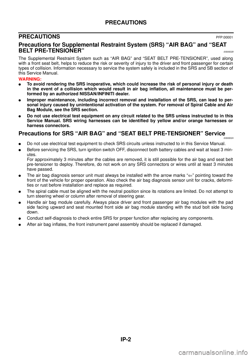
IP-2
PRECAUTIONS
PRECAUTIONS
PFP:00001
Precautions for Supplemental Restraint System (SRS) “AIR BAG” and “SEAT
BELT PRE-TENSIONER”
EIS00DZ8
The Supplemental Restraint System such as “AIR BAG” and “SEAT BELT PRE-TENSIONER”, used along
with a front seat belt, helps to reduce the risk or severity of injury to the driver and front passenger for certain
types of collision. Information necessary to service the system safely is included in the SRS and SB section of
this Service Manual.
WARNING:
lTo avoid rendering the SRS inoperative, which could increase the risk of personal injury or death
in the event of a collision which would result in air bag inflation, all maintenance must be per-
formed by an authorized NISSAN/INFINITI dealer.
lImproper maintenance, including incorrect removal and installation of the SRS, can lead to per-
sonal injury caused by unintentional activation of the system. For removal of Spiral Cable and Air
Bag Module, see the SRS section.
lDo not use electrical test equipment on any circuit related to the SRS unless instructed to in this
Service Manual. SRS wiring harnesses can be identified by yellow and/or orange harnesses or
harness connectors.
Precautions for SRS “AIR BAG” and “SEAT BELT PRE-TENSIONER” ServiceEIS00DZ4
lDo not use electrical test equipment to check SRS circuits unless instructed to in this Service Manual.
lBefore servicing the SRS, turn ignition switch OFF, disconnect both battery cables and wait at least 3 min-
utes.
For approximately 3 minutes after the cables are removed, it is still possible for the air bag and seat belt
pre-tensioner to deploy. Therefore, do not work on any SRS connectors or wires until at least 3 minutes
have passed.
lThe air bag diagnosis sensor unit must always be installed with the arrow marks “Ü” pointing toward the
front of the vehicle for proper operation. Also check the air bag diagnosis sensor unit for cracks, deformi-
ties or rust before installation and replace as required.
lThe spiral cable must be aligned with the neutral position since its rotations are limited. Do not attempt to
turn steering wheel or column after removal of steering gear.
lHandle air bag module carefully. Always place driver and front passenger air bag modules with the pad
side facing upward and seat mounted front side air bag module standing with the stud bolt side facing
down.
lConduct self-diagnosis to check entire SRS for proper function after replacing any components.
lAfter air bag inflates, the front instrument panel assembly should be replaced if damaged.
Page 1769 of 3171
IP-10
INSTRUMENT PANEL ASSEMBLY
INSTRUMENT PANEL ASSEMBLY
PFP:68200
Removal and InstallationEIS00DYZ
INSTRUMENT PANEL
Removal
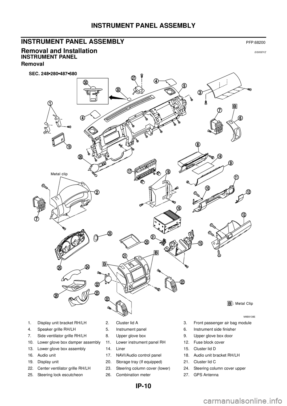
1. Display unit bracket RH/LH 2. Cluster lid A 3. Front passenger air bag module
4. Speaker grille RH/LH 5. Instrument panel 6. Instrument side finisher
7. Side ventilator grille RH/LH 8. Upper glove box 9. Upper glove box door
10. Lower glove box damper assembly 11. Lower instrument panel RH 12. Fuse block cover
13. Lower glove box assembly 14. Liner 15. Cluster lid D
16. Audio unit 17. NAVI/Audio control panel 18. Audio unit bracket RH/LH
19. Display unit 20. Storage tray (If equipped) 21. Cluster lid C
22. Center ventilator grille RH/LH 23. Steering column cover (lower) 24. Steering column cover upper
25. Steering lock escutcheon 26. Combination meter 27. GPS Antenna
MIIB9138E
Page 1770 of 3171
INSTRUMENT PANEL ASSEMBLY
IP-11
C
D
E
F
G
H
J
K
L
MA
B
IP
1. Remove the center console. Refer toIP-16, "CENTER CONSOLE".
2. Remove the steering column covers. Refer toPS-11, "
STEERING COLUMN".
3. Remove the combination meter. Refer toIP-13, "
COMBINATION METER".
4. Release then disconnect the optical sensor harness.
5. Remove the LH and RH front pillar upper garnish.
6. Remove cluster lid C.
7. Remove screws fixing CD Audio bracket, then remove CD Audio unit assembly. (If equipped). Refer toAV-
73, "Auido Unit (1CD Player Type)".
8. Remove cluster lid D. Refer toIP-12, "
CLUSTER LID D".
9. Remove screws fixing GPS Antenna, then move GPS Antenna.
10. Remove screws fixing display unit bracket, then remove display unit assembly. (If equipped)
11. Remove front passenger air bag module.
12. Remove instrument panel.
lDisconnect harnesses to instrument panel speakers LH and RH and remove speakers.
lDisconnect all remaining harnesses.
lRemove the passenger air bag module. Refer toSRS-40, "FRONT PASSENGER AIR BAG MODULE".
Installation
Installation is in the reverse order of removal.
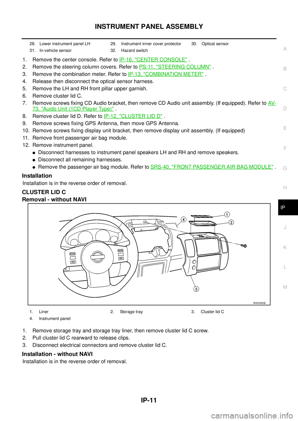
CLUSTER LID C
Removal - without NAVI
1. Remove storage tray and storage tray liner, then remove cluster lid C screw.
2. Pull cluster lid C rearward to release clips.
3. Disconnect electrical connectors and remove cluster lid C.
Installation - without NAVI
Installation is in the reverse order of removal.
28. Lower instrument panel LH 29. Instrument inner cover protector 30. Optical sensor
31. In-vehicle sensor 32. Hazard switch
WIIA0563E
1. Liner 2. Storage tray 3. Cluster lid C
4. Instrument panel
Page 1772 of 3171
INSTRUMENT PANEL ASSEMBLY
IP-13
C
D
E
F
G
H
J
K
L
MA
B
IP
LOWER INSTRUMENT PANEL LH
Removal
1. Remove LH front kick plate.
2. Remove lower dash side finisher. Refer toEI-34, "
Removal".
3. Remove front pillar finisher. Refer toEI-35, "
Removal".
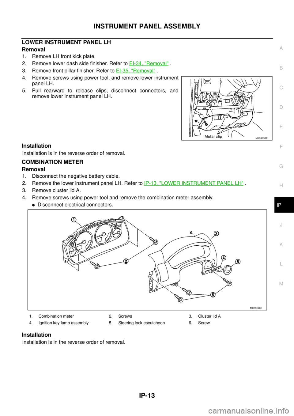
4. Remove screws using power tool, and remove lower instrument
panel LH.
5. Pull rearward to release clips, disconnect connectors, and
remove lower instrument panel LH.
Installation
Installation is in the reverse order of removal.
COMBINATION METER
Removal
1. Disconnect the negative battery cable.
2. Remove the lower instrument panel LH. Refer toIP-13, "
LOWER INSTRUMENT PANEL LH".
3. Remove cluster lid A.
4. Remove screws using power tool and remove the combination meter assembly.
lDisconnect electrical connectors.
Installation
Installation is in the reverse order of removal.
MIIB9139E
1. Combination meter 2. Screws 3. Cluster lid A
4. Ignition key lamp assembly 5. Steering lock escutcheon 6. Screw
MIIB9140E
Page 2195 of 3171
LT-112
LIGHTING AND TURN SIGNAL SWITCH
LIGHTING AND TURN SIGNAL SWITCH
PFP:25540
Removal and InstallationEKS00P8N
REMOVAL
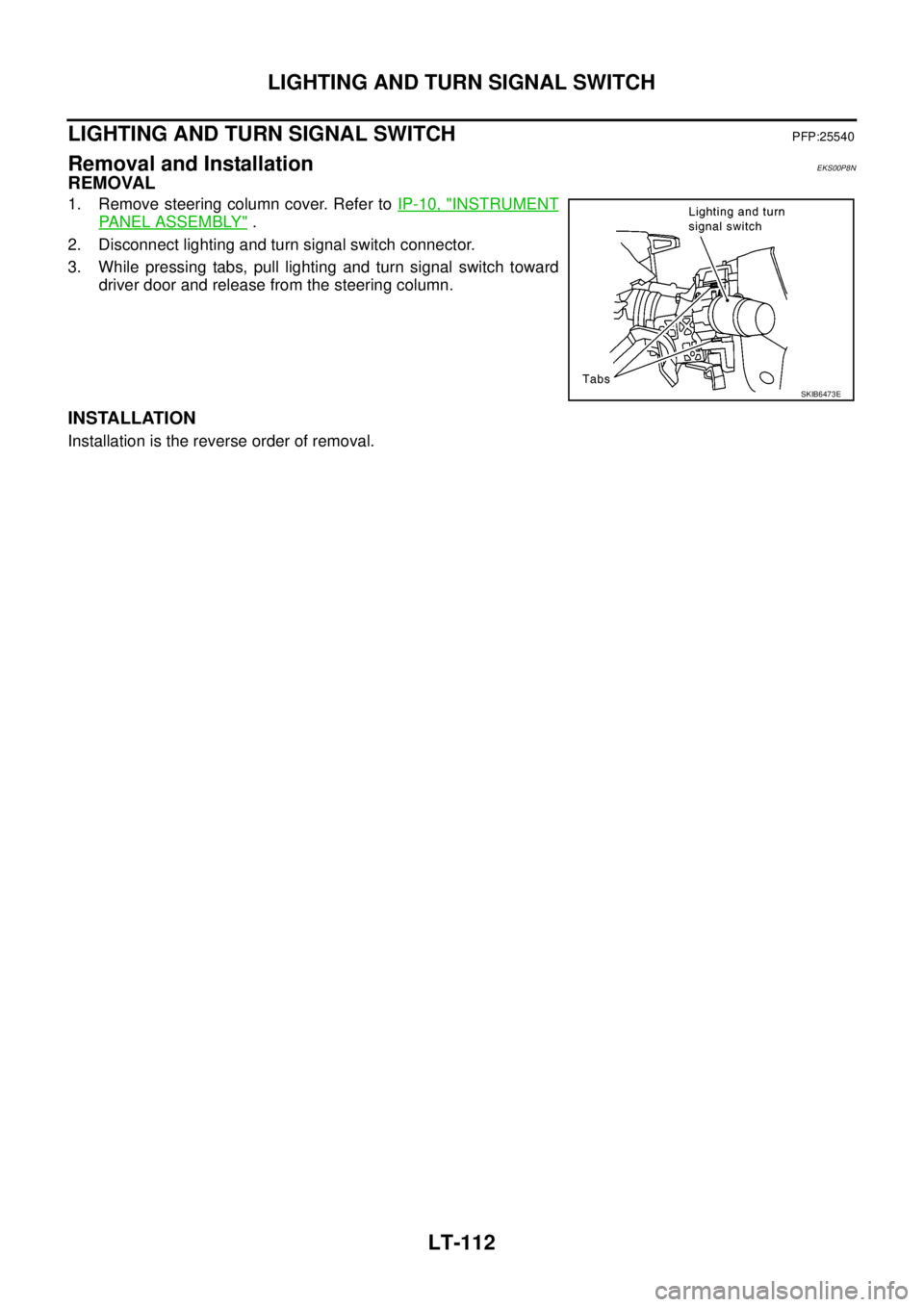
1. Remove steering column cover. Refer toIP-10, "INSTRUMENT
PANEL ASSEMBLY".
2. Disconnect lighting and turn signal switch connector.
3. While pressing tabs, pull lighting and turn signal switch toward
driver door and release from the steering column.
INSTALLATION
Installation is the reverse order of removal.
SKIB6473E