Page 2495 of 3171
MTC-108
DEFROSTERDOORMOTOR
DEFROSTER DOOR MOTOR
PFP:27733
ComponentsEJS005H1
Defroster Door Motor - Heater and Cooling Unit Assembly
Removal and InstallationEJS006D8
REMOVAL
1. Remove the steering member.
2. Remove the heater and cooling unit assembly. Refer toMTC-103, "
HEATER&COOLING UNIT ASSEM-
BLY".
3. Disconnect the defroster door motor electrical connector.
4. Remove the three screws and remove the defroster door motor.
INSTALLATION
Installation is in the reverse order of removal.
MJIB0249E
1. Heater and cooling unit assembly 2. Intake door motor 3. Air mix door motor
4. Blower motor resistor 5. Mode door motor 6. Defroster door motor
Page 2496 of 3171
INTAKE DOOR MOTOR
MTC-109
C
D
E
F
G
H
I
K
L
MA
B
MTC
INTAKE DOOR MOTORPFP:27730
ComponentsEJS005H2
Intake Door Motor - Heater and Cooling Unit Assembly
Removal and InstallationEJS006D9
REMOVAL
1. Remove the steering member.
2. Remove the heater and cooling unit assembly. Refer toMTC-103, "
HEATER&COOLING UNIT ASSEM-
BLY".
3. Disconnect the intake door motor electrical connector.
4. Remove the three screws and remove the intake door motor.
INSTALLATION
Installation is in the reverse order of removal.
MJIB0249E
1. Heater and cooling unit assembly 2. Intake door motor 3. Air mix door motor
4. Blower motor resistor 5. Mode door motor 6. Defroster door motor
Page 2497 of 3171
MTC-110
MODE DOOR MOTOR
MODE DOOR MOTOR
PFP:27731
ComponentsEJS005H3
Mode Door Motor - Heater and Cooling Unit Assembly
Removal and InstallationEJS006DA
REMOVAL
1. Remove the steering member.
2. Remove the heater and cooling unit assembly. Refer toMTC-103, "
HEATER&COOLING UNIT ASSEM-
BLY".
3. Disconnect the mode door motor electrical connector.
4. Remove the two screws and remove the mode door motor.
INSTALLATION
Installation is in the reverse order of removal.
MJIB0249E
1. Heater and cooling unit assembly 2. Intake door motor 3. Air mix door motor
4. Blower motor resistor 5. Mode door motor 6. Defroster door motor
Page 2498 of 3171
AIR MIX DOOR MOTOR
MTC-111
C
D
E
F
G
H
I
K
L
MA
B
MTC
AIR MIX DOOR MOTORPFP:27732
ComponentsEJS005H4
Air Mix Door Motor - Heater and Cooling Unit Assembly
Removal and InstallationEJS005H5
REMOVAL
1. Remove the steering member.
2. Remove the heater and cooling unit assembly. Refer toMTC-103, "
HEATER&COOLING UNIT ASSEM-
BLY".
3. Disconnect the air mix door motor electrical connector.
4. Remove the three screws and remove the air mix door motor.
INSTALLATION
Installation is in the reverse order of removal.
MJIB0249E
1. Heater and cooling unit assembly 2. Intake door motor 3. Air mix door motor
4. Blower motor resistor 5. Mode door motor 6. Defroster door motor
Page 2499 of 3171
MTC-112
BLOWER MOTOR RESISTOR
BLOWER MOTOR RESISTOR
PFP:27077
ComponentsEJS005H6
Blower Motor Resistor - Heater and Cooling Unit Assembly
Removal and InstallationEJS006DB
REMOVAL
1. Remove the steering member.
2. Remove the heater and cooling unit assembly. Refer toMTC-103, "
HEATER&COOLING UNIT ASSEM-
BLY".
3. Disconnect the blower motor resistor electrical connector.
4. Remove the two screws and remove the blower motor resistor.
INSTALLATION
Installation is in the reverse order of removal.
MJIB0249E
1. Heater and cooling unit assembly 2. Intake door motor 3. Air mix door motor
4. Blower motor resistor 5. Mode door motor 6. Defroster door motor
Page 2597 of 3171

PG-68
HARNESS
Wiring Diagram Codes (Cell Codes)
EKS00LJ9
Use the chart below to find out what each wiring diagram code stands for.
Refer to the wiring diagram code in the alphabetical index to find the location (page number) of each wiring
diagram.
Code Section Wiring Diagram Name
A/C,A ATC Auto Air Conditioner
A/C,M MTC Manual Air Conditioner
ABS BRC Anti-lock Brake System
APP1PW EC Accelerator Pedal Position Sensor 1 Power
APP2PW EC Accelerator Pedal Position Sensor 2 Power
APPS1 EC Accelerator Pedal Position Sensor 1
APPS2 EC Accelerator Pedal Position Sensor 2
APPS3 EC Accelerator Pedal Position Sensor
ASC/BS EC ASCD Brake Switch
ASC/SW EC ASCD Steering Switch
ASCBOF EC ASCD Brake Switch
ASCIND EC ASCD Indicator
AT/IND DI A/T Indicator Lamp
AUDIO AV Audio
AUTO/L LT Auto Lignt System
BACK/L LT Back-up Lamp
BOOST EC Turbocharger Boost Sensor
CAN AT CAN Communication Line
CAN EC CAN Communication Line
CAN LAN CAN System
CHARGE SC Charging System
CHIME DI Warning Chime
CIGER WW Cigarette Lighter
CKPS EC Crankshaft Position Sensor
CMPS EC Camshaft Position Sensor
COMBSW LT Combination Switch
COMM AV Audio Visual Communication Line
COMPAS DI Compass
COOL/F EC Cooling Fan Control
D/LOCK BL Power Door Lock
DIFLOC RFD Rear Final Drive
DEF GW Rear Window Defogger
DTRL LT Headlamp — With Daytime Running Light System
ECMRLY EC ECM Relay
ECTS EC Engine Coolant Temperature Sensor
EGRVLV EC EGR Volume Control System
EMNT EC Electronic Controlled Engine Mount Control Solenoid Valve
F/FOG LT Front Fog Lamp
F/PUMP EC Fuel Pump
FRPS EC Fuel Rail Pressure Sensor
FTS AT A/T Fluid Temperature Sensor
Page 2617 of 3171

PR-2
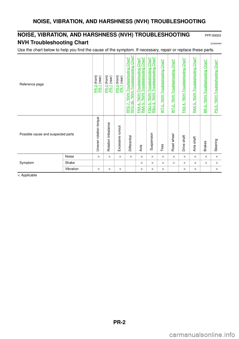
NOISE, VIBRATION, AND HARSHNESS (NVH) TROUBLESHOOTING
NOISE, VIBRATION, AND HARSHNESS (NVH) TROUBLESHOOTING
PFP:00003
NVH Troubleshooting ChartEDS002WN
Use the chart below to help you find the cause of the symptom. If necessary, repair or replace these parts.
´: ApplicableReference page
PR-3
(front)
PR-7(rear)
PR-3(front)
PR-7(rear)
PR-3(front)
PR-7(rear)
RFD-7, "
NVH Troubleshooting Chart
"
RFD-39, "
NVH Troubleshooting Chart
"
FA X -4 , "
NVH Troubleshooting Chart
"
RAX-5, "
NVH Troubleshooting Chart
"
FSU-5, "
NVH Troubleshooting Chart
"
RSU-3, "
NVH Troubleshooting Chart
"
WT-2, "
NVH Troubleshooting Chart
"
WT-2, "
NVH Troubleshooting Chart
"
FA X -4 , "
NVH Troubleshooting Chart
"
RAX-5, "
NVH Troubleshooting Chart
"
BR-5, "
NVH Troubleshooting Chart
"
PS-5, "
NVH Troubleshooting Chart
"
Possible cause and suspected parts
Uneven rotation torque
Rotation imbalance
Excessive runout
Differential
Axle
Suspension
Tires
Road wheel
Drive shaft
Axle shaft
Brakes
Steering
SymptomNoise´´´´´´´´´´´´
Shake´´´´´´´´
Vibration´´´ ´´´ ´´ ´
Page 2628 of 3171

PS-1
POWER STEERING SYSTEM
G STEERING
CONTENTS
C
D
E
F
H
I
J
K
L
M
SECTIONPS
A
B
PS
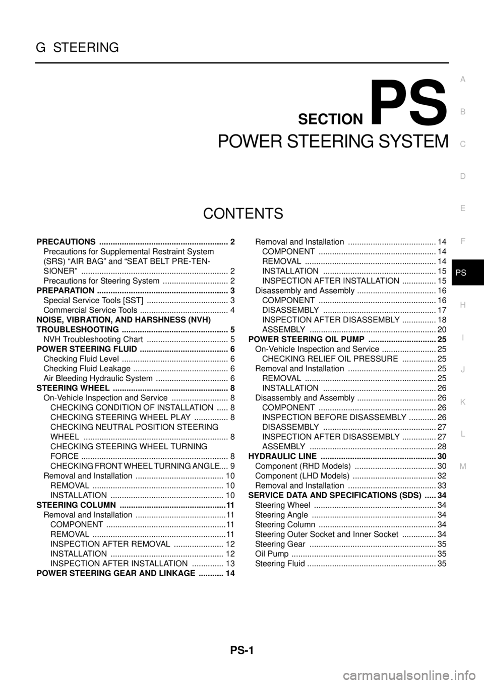
POWER STEERING SYSTEM
PRECAUTIONS .......................................................... 2
Precautions for Supplemental Restraint System
(SRS)“AIRBAG”and“SEATBELTPRE-TEN-
SIONER” .................................................................. 2
Precautions for Steering System .............................. 2
PREPARATION ........................................................... 3
Special Service Tools [SST] ..................................... 3
Commercial Service Tools ........................................ 4
NOISE, VIBRATION, AND HARSHNESS (NVH)
TROUBLESHOOTING ................................................ 5
NVH Troubleshooting Chart ..................................... 5
POWER STEERING FLUID ........................................ 6
Checking Fluid Level ................................................ 6
Checking Fluid Leakage ........................................... 6
Air Bleeding Hydraulic System ................................. 6
STEERING WHEEL .................................................... 8
On-Vehicle Inspection and Service .......................... 8
CHECKING CONDITION OF INSTALLATION ...... 8
CHECKING STEERING WHEEL PLAY ................ 8
CHECKING NEUTRAL POSITION STEERING
WHEEL ................................................................. 8
CHECKING STEERING WHEEL TURNING
FORCE .................................................................. 8
CHECKING FRONT WHEEL TURNING ANGLE..... 9
Removal and Installation ........................................ 10
REMOVAL ........................................................... 10
INSTALLATION ................................................... 10
STEERING COLUMN ................................................11
Removal and Installation ......................................... 11
COMPONENT ...................................................... 11
REMOVAL ............................................................ 11
INSPECTION AFTER REMOVAL ....................... 12
INSTALLATION ................................................... 12
INSPECTION AFTER INSTALLATION ............... 13
POWER STEERING GEAR AND LINKAGE ............ 14Removal and Installation ........................................ 14
COMPONENT ..................................................... 14
REMOVAL ........................................................... 14
INSTALLATION ................................................... 15
INSPECTION AFTER INSTALLATION ................ 15
Disassembly and Assembly .................................... 16
COMPONENT ..................................................... 16
DISASSEMBLY ................................................... 17
INSPECTION AFTER DISASSEMBLY ................ 18
ASSEMBLY ......................................................... 20
POWER STEERING OIL PUMP ............................... 25
On-Vehicle Inspection and Service ......................... 25
CHECKING RELIEF OIL PRESSURE ................ 25
Removal and Installation ........................................ 25
REMOVAL ........................................................... 25
INSTALLATION ................................................... 26
Disassembly and Assembly .................................... 26
COMPONENT ..................................................... 26
INSPECTION BEFORE DISASSEMBLY ............. 26
DISASSEMBLY ................................................... 27
INSPECTION AFTER DISASSEMBLY ................ 27
ASSEMBLY ......................................................... 28
HYDRAULIC LINE .................................................... 30
Component (RHD Models) ..................................... 30
Component (LHD Models) ...................................... 32
Removal and Installation ........................................ 33
SERVICE DATA AND SPECIFICATIONS (SDS) ...... 34
Steering Wheel ....................................................... 34
Steering Angle ........................................................ 34
Steering Column ..................................................... 34
Steering Outer Socket and Inner Socket ................ 34
Steering Gear ......................................................... 35
Oil Pump ................................................................. 35
Steering Fluid .......................................................... 35