Page 2654 of 3171

POWER STEERING OIL PUMP
PS-27
C
D
E
F
H
I
J
K
L
MA
B
PS
DISASSEMBLY
NOTE:
Secure oil pump in a vise if necessary.
CAUTION:
Use copper plates when securing in a vise.
1. Remove rear bracket mounting bolts, and then remove rear bracket from rear cover.
2. Remove rear cover mounting bolts, and then remove rear cover from body assembly.
3. Remove gasket from body assembly.
4. Remove dowel pin, cartridge and side plate from body assembly.
5. Remove pulley mounting nut and washer, then remove pulley from drive shaft.
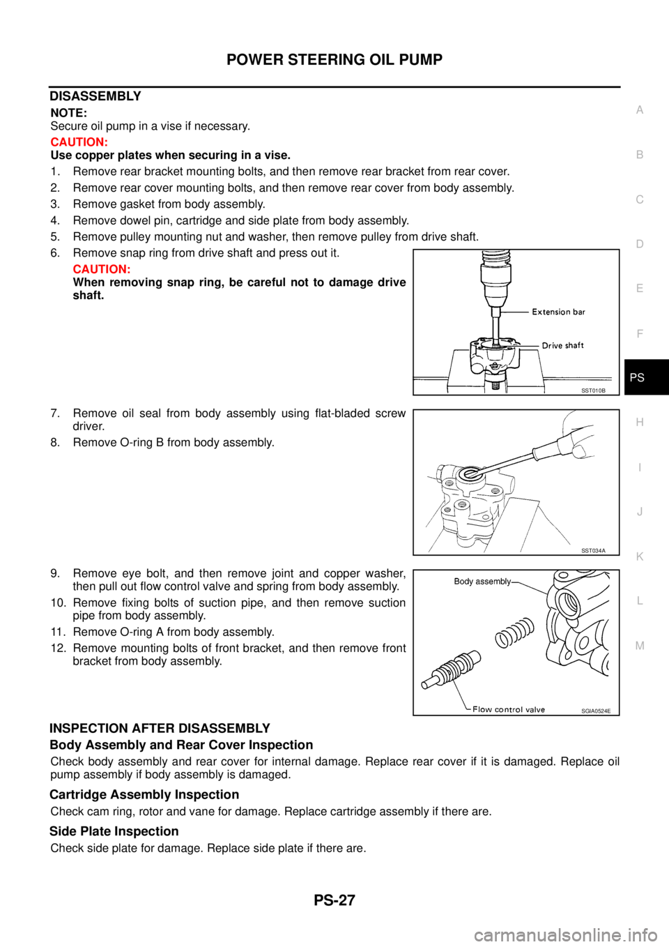
6. Remove snap ring from drive shaft and press out it.
CAUTION:
When removing snap ring, be careful not to damage drive
shaft.
7. Remove oil seal from body assembly using flat-bladed screw
driver.
8. Remove O-ring B from body assembly.
9. Remove eye bolt, and then remove joint and copper washer,
then pull out flow control valve and spring from body assembly.
10. Remove fixing bolts of suction pipe, and then remove suction
pipe from body assembly.
11. Remove O-ring A from body assembly.
12. Remove mounting bolts of front bracket, and then remove front
bracket from body assembly.
INSPECTION AFTER DISASSEMBLY
Body Assembly and Rear Cover Inspection
Check body assembly and rear cover for internal damage. Replace rear cover if it is damaged. Replace oil
pump assembly if body assembly is damaged.
Cartridge Assembly Inspection
Check cam ring, rotor and vane for damage. Replace cartridge assembly if there are.
Side Plate Inspection
Check side plate for damage. Replace side plate if there are.
SST010B
SST034A
SGIA0524E
Page 2655 of 3171

PS-28
POWER STEERING OIL PUMP
Flow Control Valve Inspection
Check flow control valve and spring for damage. Replace if there are.
ASSEMBLY
NOTE:
Secureoilpumpinaviseifnecessary.
CAUTION:
Use copper plates when securing in a vise.
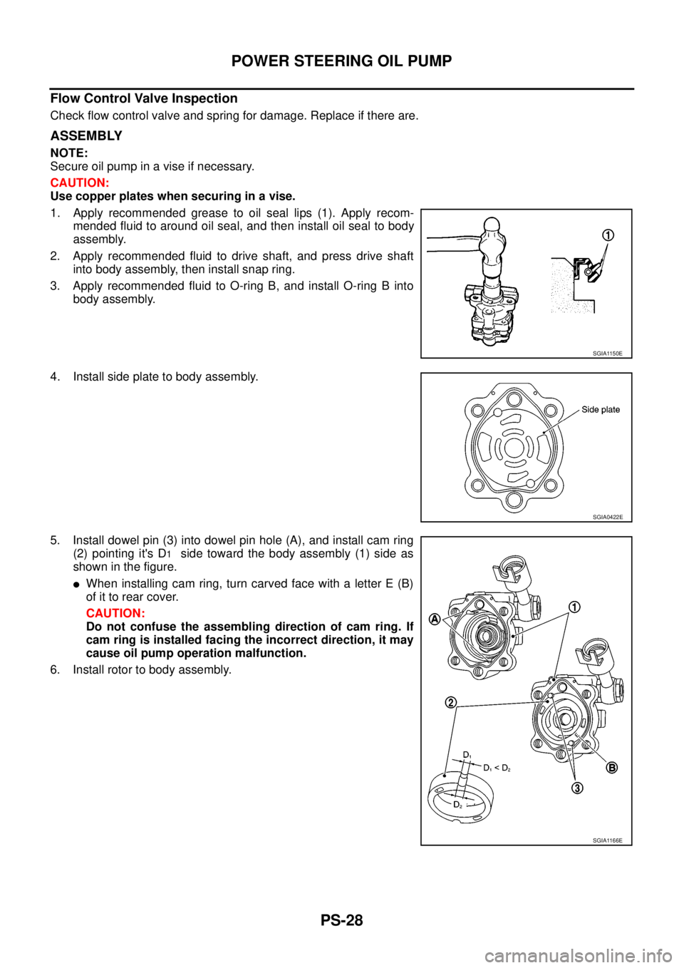
1. Apply recommended grease to oil seal lips (1). Apply recom-
mended fluid to around oil seal, and then install oil seal to body
assembly.
2. Apply recommended fluid to drive shaft, and press drive shaft
into body assembly, then install snap ring.
3. Apply recommended fluid to O-ring B, and install O-ring B into
body assembly.
4. Install side plate to body assembly.
5. Install dowel pin (3) into dowel pin hole (A), and install cam ring
(2) pointing it's D
1side toward the body assembly (1) side as
showninthefigure.
lWhen installing cam ring, turn carved face with a letter E (B)
of it to rear cover.
CAUTION:
Do not confuse the assembling direction of cam ring. If
cam ring is installed facing the incorrect direction, it may
cause oil pump operation malfunction.
6. Install rotor to body assembly.
SGIA1150E
SGIA0422E
SGIA1166E
Page 2656 of 3171
POWER STEERING OIL PUMP
PS-29
C
D
E
F
H
I
J
K
L
MA
B
PS
lWhen installing rotor, turn mark face on rotor to body assem-
bly.
7. Install vane to rotor so that arc of vane faces cam ring side.
8. Check if drive shaft turns smoothly.
9. Install gasket to body assembly.
10. Install rear cover to body assembly, and then tighten mounting
bolts to the specified torque.
11. Install rear bracket to body assembly, and tighten the mounting
bolts to the specified torque.
12. Install front bracket to body assembly, and tighten the mounting
bolts to the specified torque.
13. Install pulley and washer to drive shaft, and then tighten lock nut
at the specified torque.
14. Install spring, flow control valve, copper washer, joint and eye-
bolt to body assembly. Then tighten eye-bolt to the specified
torque.
15. Apply recommended fluid to O-ring A, and then install O-ring A to body assembly.
16. Install suction pipe to body assembly.
SGIA0874E
SGIA0613E
SGIA0425E
Page 2657 of 3171
PS-30
HYDRAULIC LINE
HYDRAULIC LINE
PFP:49721
Component (RHD Models)EGS001LO
CAUTION:
Securely insert harness connector to pressure sensor.
1. Reservoir tank 2. Reservoir tank bracket 3. Suction hose
4. High pressure hose 5. Oil pump assembly 6. Steering gear assembly
SGIA1319E
Page 2659 of 3171
PS-32
HYDRAULIC LINE
Component (LHD Models)
EGS001LP
CAUTION:
Securely insert harness connector to pressure sensor.
1. Reservoir tank 2. Reservoir tank bracket 3. Suction hose
4. High pressure hose 5. Oil pump assembly 6. Steering gear assembly
7. Eye-bolt 8. Pressure sensor 9. Copper washer
SGIA1320E
Page 2661 of 3171

PS-34
SERVICE DATA AND SPECIFICATIONS (SDS)
SERVICE DATA AND SPECIFICATIONS (SDS)
PFP:00030
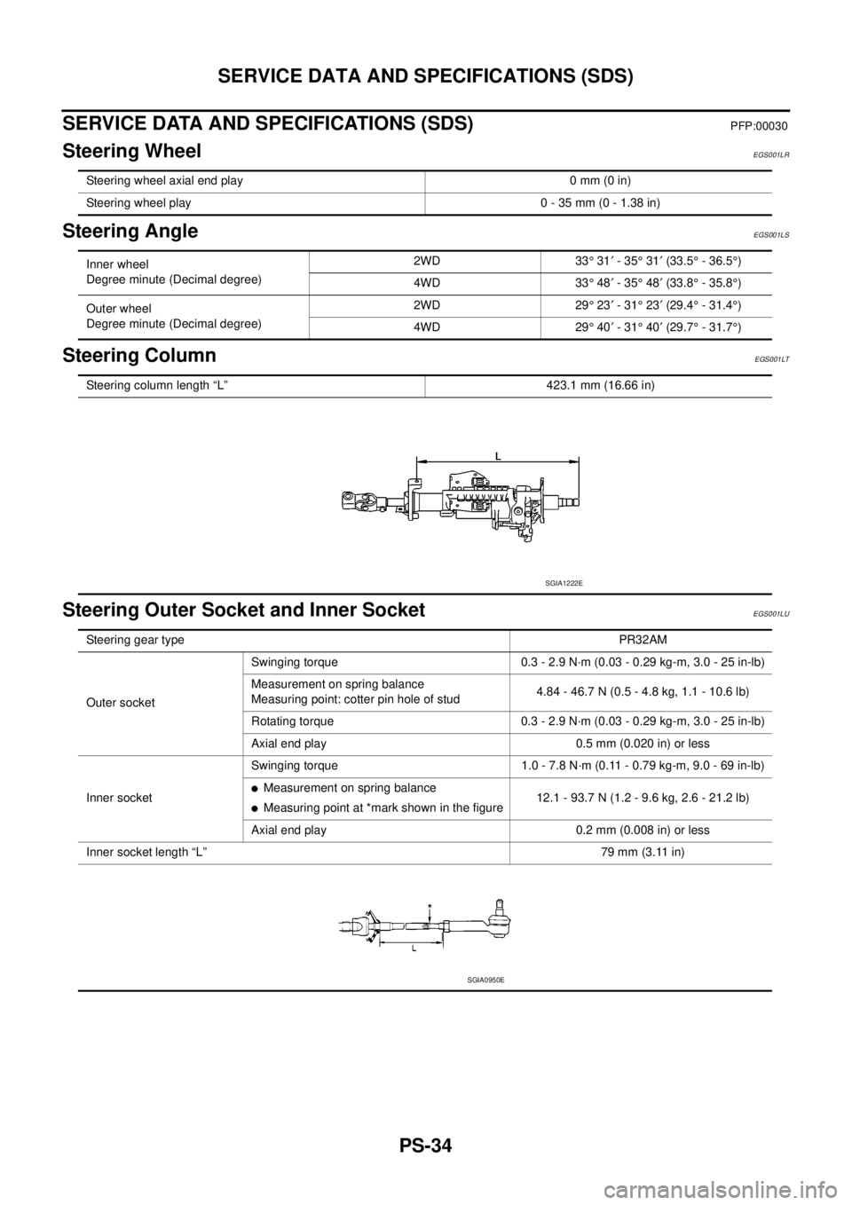
Steering WheelEGS001LR
Steering AngleEGS001LS
Steering ColumnEGS001LT
Steering Outer Socket and Inner SocketEGS001LU
Steering wheel axial end play 0 mm (0 in)
Steering wheel play 0 - 35 mm (0 - 1.38 in)
Inner wheel
Degree minute (Decimal degree)2WD 33°31¢-35°31¢(33.5°- 36.5°)
4WD 33°48¢-35°48¢(33.8°- 35.8°)
Outer wheel
Degree minute (Decimal degree)2WD 29°23¢-31°23¢(29.4°- 31.4°)
4WD 29°40¢-31°40¢(29.7°- 31.7°)
Steering column length “L” 423.1 mm (16.66 in)
SGIA1222E
Steering gear typePR32AM
Outer socketSwinging torque 0.3 - 2.9 N·m (0.03 - 0.29 kg-m, 3.0 - 25 in-lb)
Measurement on spring balance
Measuring point: cotter pin hole of stud4.84 - 46.7 N (0.5 - 4.8 kg, 1.1 - 10.6 lb)
Rotating torque 0.3 - 2.9 N·m (0.03 - 0.29 kg-m, 3.0 - 25 in-lb)
Axial end play 0.5 mm (0.020 in) or less
Inner socketSwinging torque 1.0 - 7.8 N·m (0.11 - 0.79 kg-m, 9.0 - 69 in-lb)
lMeasurement on spring balance
lMeasuring point at *mark shown in the figure12.1 - 93.7 N (1.2 - 9.6 kg, 2.6 - 21.2 lb)
Axial end play 0.2 mm (0.008 in) or less
Inner socket length “L”79 mm (3.11 in)
SGIA0950E
Page 2662 of 3171
SERVICE DATA AND SPECIFICATIONS (SDS)
PS-35
C
D
E
F
H
I
J
K
L
MA
B
PS
Steering GearEGS001LV
Oil PumpEGS001LW
Steering FluidEGS001LX
Steering gear modelPR32AM
Rack neutral position, dimension “L” (rack stroke) 84 mm (3.31 in)
SGIA0877E
Oil pump relief hydraulic pressure
8,500 - 9,300 kpa (86.7 - 94.9 kg/cm2, 1,233 - 1,349 psi)
Fluid capacity
Approx. 1.0 (1 - 1/8 US qt, 7/8 Imp qt)
Page 2710 of 3171
![NISSAN NAVARA 2005 Repair Workshop Manual NOISE, VIBRATION, AND HARSHNESS (NVH) TROUBLESHOOTING
RFD-7
[WITH LIMITED SLIP DIFFERENTIAL]
C
E
F
G
H
I
J
K
L
MA
B
RFD
NOISE, VIBRATION, AND HARSHNESS (NVH) TROUBLESHOOTINGPFP:00003
NVH Troubleshooti NISSAN NAVARA 2005 Repair Workshop Manual NOISE, VIBRATION, AND HARSHNESS (NVH) TROUBLESHOOTING
RFD-7
[WITH LIMITED SLIP DIFFERENTIAL]
C
E
F
G
H
I
J
K
L
MA
B
RFD
NOISE, VIBRATION, AND HARSHNESS (NVH) TROUBLESHOOTINGPFP:00003
NVH Troubleshooti](/manual-img/5/57362/w960_57362-2709.png)
NOISE, VIBRATION, AND HARSHNESS (NVH) TROUBLESHOOTING
RFD-7
[WITH LIMITED SLIP DIFFERENTIAL]
C
E
F
G
H
I
J
K
L
MA
B
RFD
NOISE, VIBRATION, AND HARSHNESS (NVH) TROUBLESHOOTINGPFP:00003
NVH Troubleshooting ChartEDS00392
Use the chart below to help you find the cause of the symptom. If necessary, repair or replace these parts.
´: ApplicableReference page
RFD-22, "
INSPECTION AFTER DISASSEMBLY
"
RFD-16, "
Tooth Contact
"
RFD-22, "
INSPECTION AFTER DISASSEMBLY
"
RFD-17, "
Backlash
"
RFD-18, "
Companion Flange Runout
"
RFD-9, "
Checking Differential Gear Oil
"
PR-2, "
NVH Troubleshooting Chart
"
RAX-5, "
NVH Troubleshooting Chart
",RSU-3, "
NVH Troubleshooting Chart
"
WT-2, "
NVH Troubleshooting Chart
"
RAX-5, "
NVH Troubleshooting Chart
"
BR-5, "
NVH Troubleshooting Chart
"
PS-5, "
NVH Troubleshooting Chart
"
Possible cause and SUSPECTED PARTS
Gear tooth rough
Gear contact improper
Tooth surfaces worn
Backlash incorrect
Companion flange excessive runout
Gear oil improper
PROPELLER SHAFT
AXLE AND SUSPENSION
TIRES
ROAD WHEEL
AXLE SHAFT
BRAKES
STEERING
Symptom Noise´´´´´´´´´´´´´