2005 NISSAN NAVARA steering
[x] Cancel search: steeringPage 2742 of 3171
![NISSAN NAVARA 2005 Repair Workshop Manual NOISE, VIBRATION AND HARSHNESS (NVH) TROUBLESHOOTING
RFD-39
[WITH ELECTRONIC LOCKING DIFFERENTIAL]
C
E
F
G
H
I
J
K
L
MA
B
RFD
NOISE, VIBRATION AND HARSHNESS (NVH) TROUBLESHOOTINGPFP:00003
NVH Troubles NISSAN NAVARA 2005 Repair Workshop Manual NOISE, VIBRATION AND HARSHNESS (NVH) TROUBLESHOOTING
RFD-39
[WITH ELECTRONIC LOCKING DIFFERENTIAL]
C
E
F
G
H
I
J
K
L
MA
B
RFD
NOISE, VIBRATION AND HARSHNESS (NVH) TROUBLESHOOTINGPFP:00003
NVH Troubles](/manual-img/5/57362/w960_57362-2741.png)
NOISE, VIBRATION AND HARSHNESS (NVH) TROUBLESHOOTING
RFD-39
[WITH ELECTRONIC LOCKING DIFFERENTIAL]
C
E
F
G
H
I
J
K
L
MA
B
RFD
NOISE, VIBRATION AND HARSHNESS (NVH) TROUBLESHOOTINGPFP:00003
NVH Troubleshooting ChartEDS003AM
Use the chart below to help you find the cause of the symptom. If necessary, repair or replace these parts.
´: ApplicableReference page
RFD-90, "
INSPECTION AFTER DISASSEMBLY
"
RFD-83, "
Tooth Contact
"
RFD-90, "
INSPECTION AFTER DISASSEMBLY
"
RFD-84, "
Backlash
"
RFD-85, "
Companion Flange Runout
"
RFD-40, "
Checking Differential Gear Oil
"
PR-2, "
NVH Troubleshooting Chart
"
RAX-5, "
NVH Troubleshooting Chart
",RSU-3, "
NVH Troubleshooting Chart
"
WT-2, "
NVH Troubleshooting Chart
"
RAX-5, "
NVH Troubleshooting Chart
"
BR-5, "
NVH Troubleshooting Chart
"
PS-5, "
NVH Troubleshooting Chart
"
Possible cause and SUSPECTED PARTS
Gear tooth rough
Gear contact improper
Tooth surfaces worn
Backlash incorrect
Companion flange excessive runout
Gear oil improper
PROPELLER SHAFT
AXLE AND SUSPENSION
TIRES
ROAD WHEEL
AXLE SHAFT
BRAKES
STEERING
Symptom Noise´´´´´´´´´´´´´
Page 2808 of 3171
NOISE, VIBRATION AND HARSHNESS (NVH) TROUBLESHOOTING
RSU-3
C
D
F
G
H
I
J
K
L
MA
B
RSU
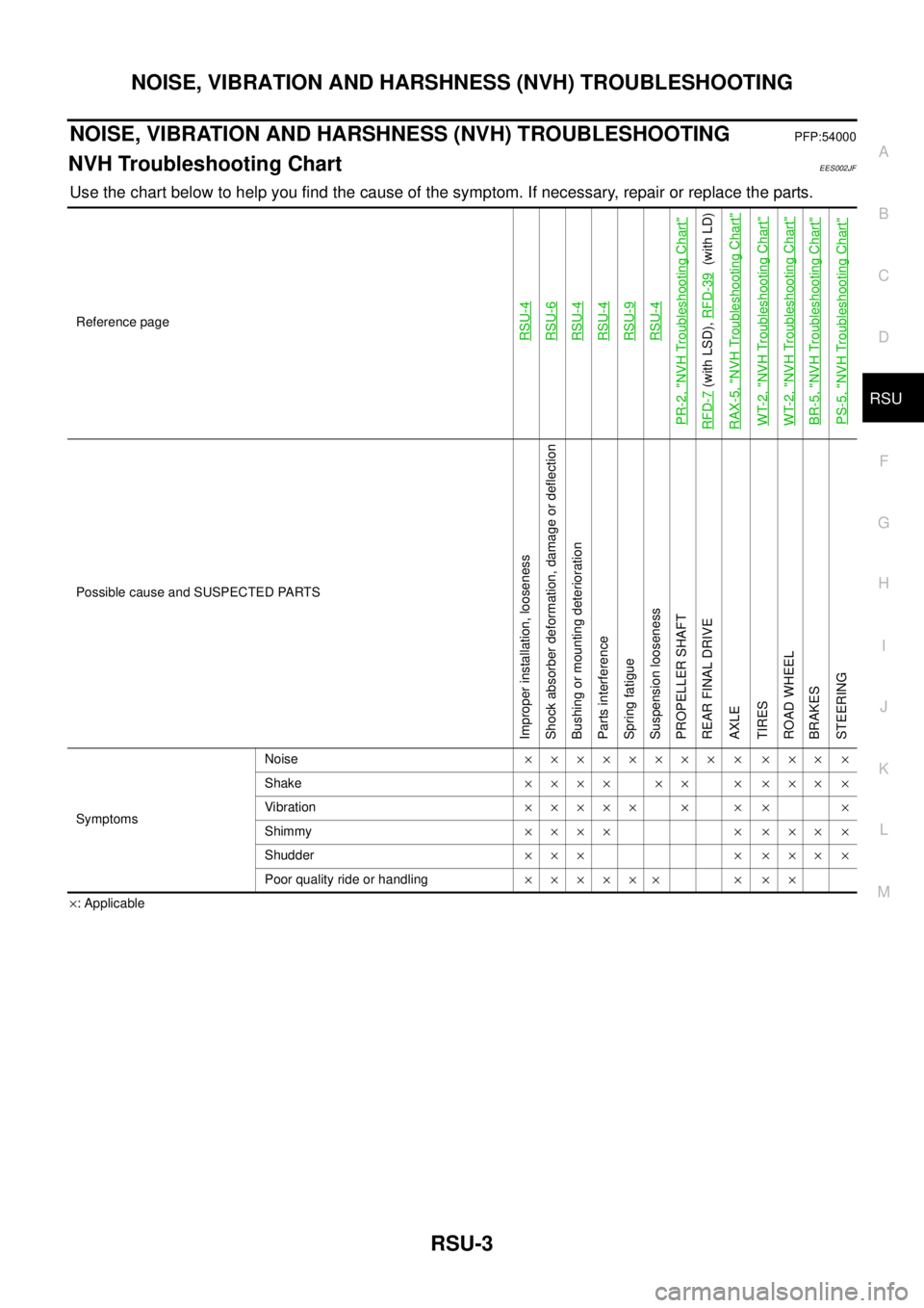
NOISE, VIBRATION AND HARSHNESS (NVH) TROUBLESHOOTINGPFP:54000
NVH Troubleshooting ChartEES002JF
Use the chart below to help you find the cause of the symptom. If necessary, repair or replace the parts.
´: Applicable Reference page
RSU-4RSU-6RSU-4RSU-4RSU-9RSU-4
PR-2, "
NVH Troubleshooting Chart
"
RFD-7
(with LSD),RFD-39
(with LD)
RAX-5, "
NVH Troubleshooting Chart
"
WT-2, "
NVH Troubleshooting Chart
"
WT-2, "
NVH Troubleshooting Chart
"
BR-5, "
NVH Troubleshooting Chart
"
PS-5, "
NVH Troubleshooting Chart
"
Possible cause and SUSPECTED PARTS
Improper installation, looseness
Shock absorber deformation, damage or deflection
Bushing or mounting deterioration
Parts interference
Spring fatigue
Suspension looseness
PROPELLER SHAFT
REAR FINAL DRIVE
AXLE
TIRES
ROAD WHEEL
BRAKES
STEERING
SymptomsNoise´´´´´´´´ ´ ´´´ ´
Shake´´´´ ´´ ´ ´´´ ´
Vibration´´´´´ ´ ´ ´ ´
Shimmy´´´´ ´ ´´´ ´
Shudder´´´ ´ ´´´ ´
Poor quality ride or handling´´´´´´ ´ ´´
Page 2912 of 3171
PRECAUTIONS
SRS-3
C
D
E
F
G
I
J
K
L
MA
B
SRS
PRECAUTIONSPFP:00001
Precautions for Supplemental Restraint System (SRS) “AIR BAG” and “SEAT
BELT PRE-TENSIONER”
EHS001Y8
The Supplemental Restraint System such as “AIR BAG” and “SEAT BELT PRE-TENSIONER”, used along
with a front seat belt, helps to reduce the risk or severity of injury to the driver and front passenger for certain
types of collision. Information necessary to service the system safely is included in the SRS and SB section of
this Service Manual.
WARNING:
lTo avoid rendering the SRS inoperative, which could increase the risk of personal injury or death
in the event of a collision which would result in air bag inflation, all maintenance must be per-
formed by an authorized NISSAN/INFINITI dealer.
lImproper maintenance, including incorrect removal and installation of the SRS, can lead to per-
sonal injury caused by unintentional activation of the system. For removal of Spiral Cable and Air
Bag Module, see the SRS section.
lDo not use electrical test equipment on any circuit related to the SRS unless instructed to in this
Service Manual. SRS wiring harnesses can be identified by yellow and/or orange harnesses or
harness connectors.
Precautions for SRS “AIR BAG” and “SEAT BELT PRE-TENSIONER” ServiceEHS001Y9
lDo not use electrical test equipment to check SRS circuits unless instructed to in this Service Manual.
lBefore servicing the SRS, turn ignition switch OFF, disconnect both battery cables and wait at least 3 min-
utes.
For approximately 3 minutes after the cables are removed, it is still possible for the air bag and seat belt
pre-tensioner to deploy. Therefore, do not work on any SRS connectors or wires until at least 3 minutes
have passed.
lDiagnosis sensor unit must always be installed with their arrow marks “Ü” pointing towards the front of the
vehicle for proper operation. Also check diagnosis sensor unit for cracks, deformities or rust before instal-
lation and replace as required.
lThe spiral cable must be aligned with the neutral position since its rotations are limited. Do not attempt to
turn steering wheel or column after removal of steering gear.
lHandle air bag module carefully. Always place driver and front passenger air bag modules with the pad
side facing upward and place front side air bag module standing with stud bolt side setting bottom.
lConduct self-diagnosis to check entire SRS for proper function after replacing any components.
lAfter air bag inflates, the front instrument panel assembly should be replaced if damaged.
lAlways replace instrument panel pad following front passenger air bag deployment.
Precautions for Trouble DiagnosisEHS001YA
When you read wiring diagrams, refer to the following:
lGI-15, "How to Read Wiring Diagrams"in GI section
lPG-4, "POWER SUPPLY ROUTING CIRCUIT"in PG section
When you perform trouble diagnosis, refer to the following:
lGI-11, "How to Follow Trouble Diagnoses"in GI section
lGI-24, "How to Perform Efficient Diagnosis for an Electrical Incident"in GI section
Check for any service bulletins before servicing the vehicle.
Page 2945 of 3171
SRS-36
DRIVER AIR BAG MODULE
DRIVER AIR BAG MODULE
PFP:K8510
Removal and InstallationEHS001XS
REMOVAL
CAUTION:
lDo not attempt to repair or replace damaged direct-connect SRS component connectors. If a
driver air bag direct-connect harness connector is damaged, the spiral cable must be replaced.
lBefore servicing the SRS, turn ignition switch OFF, disconnect both battery cables and wait at
least 3 minutes.
lWhen servicing the SRS, do not work from directly in front of air bag module.
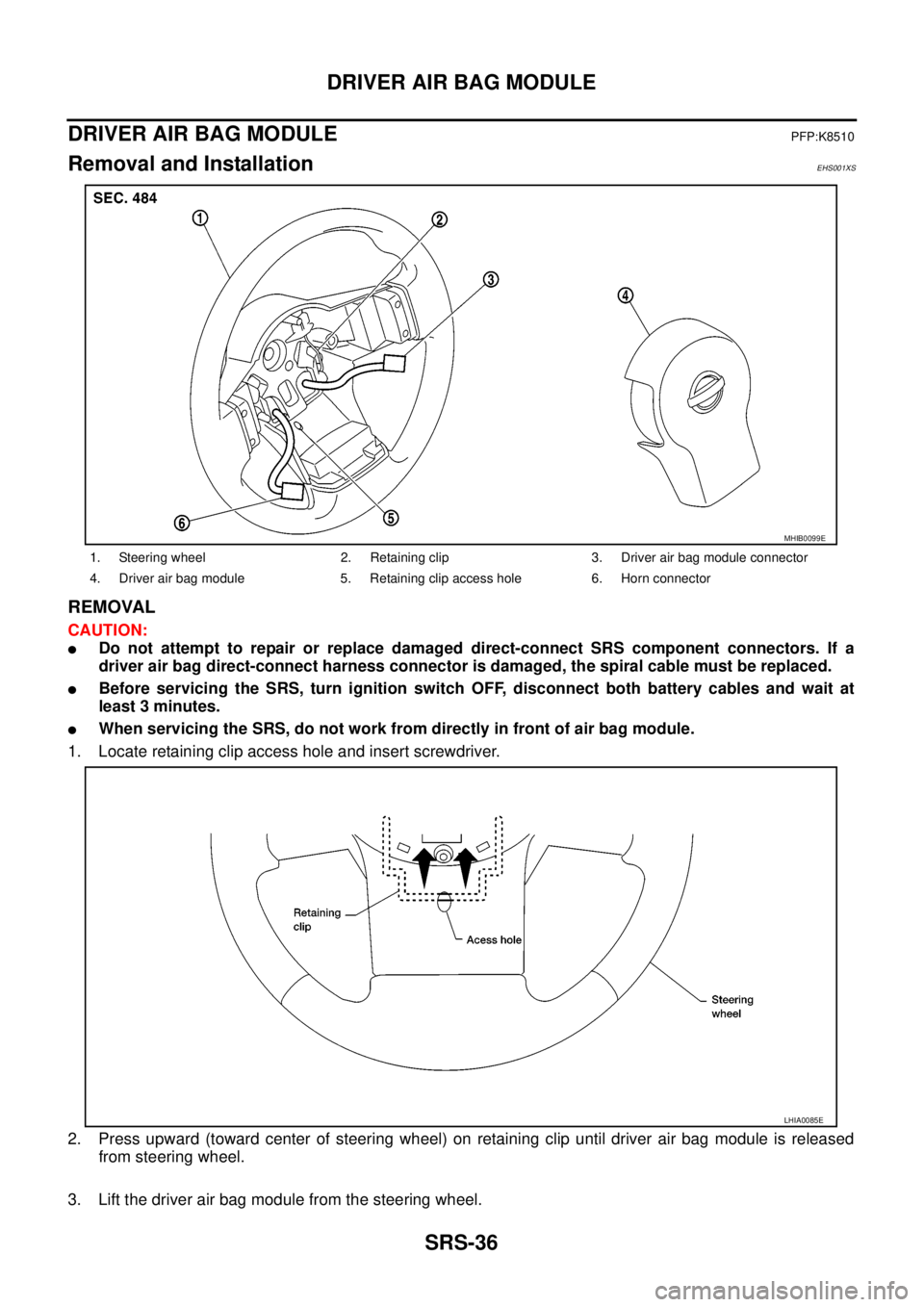
1. Locate retaining clip access hole and insert screwdriver.
2. Press upward (toward center of steering wheel) on retaining clip until driver air bag module is released
from steering wheel.
3. Lift the driver air bag module from the steering wheel.
1. Steering wheel 2. Retaining clip 3. Driver air bag module connector
4. Driver air bag module 5. Retaining clip access hole 6. Horn connector
MHIB0099E
LHIA0085E
Page 2947 of 3171
SRS-38
SPIRAL CABLE
SPIRAL CABLE
PFP:25554
Removal and InstallationEHS001XT
REMOVAL
CAUTION:
lBefore servicing the SRS, turn ignition switch OFF, disconnect both battery cables and wait at
least 3 minutes.
lWhen servicing the SRS, do not work from directly in front of air bag module.
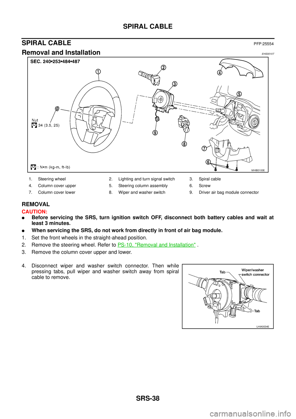
1. Set the front wheels in the straight-ahead position.
2. Remove the steering wheel. Refer toPS-10, "
Removal and Installation".
3. Remove the column cover upper and lower.
4. Disconnect wiper and washer switch connector. Then while
pressing tabs, pull wiper and washer switch away from spiral
cable to remove.
MHIB0100E
1. Steering wheel 2. Lighting and turn signal switch 3. Spiral cable
4. Column cover upper 5. Steering column assembly 6. Screw
7. Column cover lower 8. Wiper and washer switch 9. Driver air bag module connector
LHIA0034E
Page 2948 of 3171
SPIRAL CABLE
SRS-39
C
D
E
F
G
I
J
K
L
MA
B
SRS
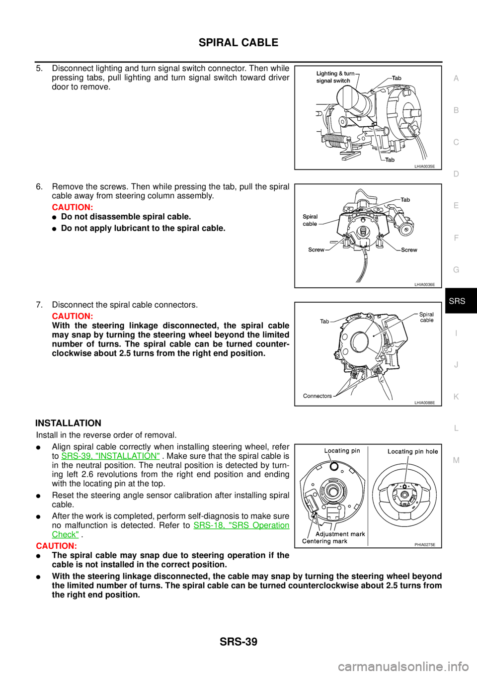
5. Disconnect lighting and turn signal switch connector. Then while
pressing tabs, pull lighting and turn signal switch toward driver
door to remove.
6. Remove the screws. Then while pressing the tab, pull the spiral
cable away from steering column assembly.
CAUTION:
lDo not disassemble spiral cable.
lDo not apply lubricant to the spiral cable.
7. Disconnect the spiral cable connectors.
CAUTION:
With the steering linkage disconnected, the spiral cable
may snap by turning the steering wheel beyond the limited
number of turns. The spiral cable can be turned counter-
clockwise about 2.5 turns from the right end position.
INSTALLATION
Install in the reverse order of removal.
lAlign spiral cable correctly when installing steering wheel, refer
toSRS-39, "
INSTALLATION". Make sure that the spiral cable is
in the neutral position. The neutral position is detected by turn-
ing left 2.6 revolutions from the right end position and ending
with the locating pin at the top.
lReset the steering angle sensor calibration after installing spiral
cable.
lAfter the work is completed, perform self-diagnosis to make sure
no malfunction is detected. Refer toSRS-18, "
SRS Operation
Check".
CAUTION:
lThe spiral cable may snap due to steering operation if the
cable is not installed in the correct position.
lWith the steering linkage disconnected, the cable may snap by turning the steering wheel beyond
the limited number of turns. The spiral cable can be turned counterclockwise about 2.5 turns from
the right end position.
LHIA0035E
LHIA0036E
LHIA0088E
PHIA0275E
Page 2949 of 3171
SRS-40
FRONT PASSENGER AIR BAG MODULE
FRONT PASSENGER AIR BAG MODULE
PFP:K8515
Removal and InstallationEHS001XU
The passenger air bag module originally installed in the vehicle uses direct-connect style harness connectors.
Service replacement passenger air bag modules use tab-locking style harness connectors. If the passenger
air bag module is replaced or if the direct-connect harness connectors are damaged, the vehicle wiring har-
ness must be modified to allow connection of the service replacement passenger air bag module. Refer to
SRS-41, "
WIRING HARNESS MODIFICATION"for wiring harness modification procedure.
REMOVAL
CAUTION:
lDo not attempt to repair or replace damaged direct-connect front passenger air bag module con-
nectors. If a direct-connect harness connector is damaged, the front passenger air bag must be
replaced and the wiring harness modified.
lBefore servicing SRS, turn the ignition switch off, disconnect both battery cables and wait at least
3 minutes.
lAlways work from the side of or under front passenger air bag module.
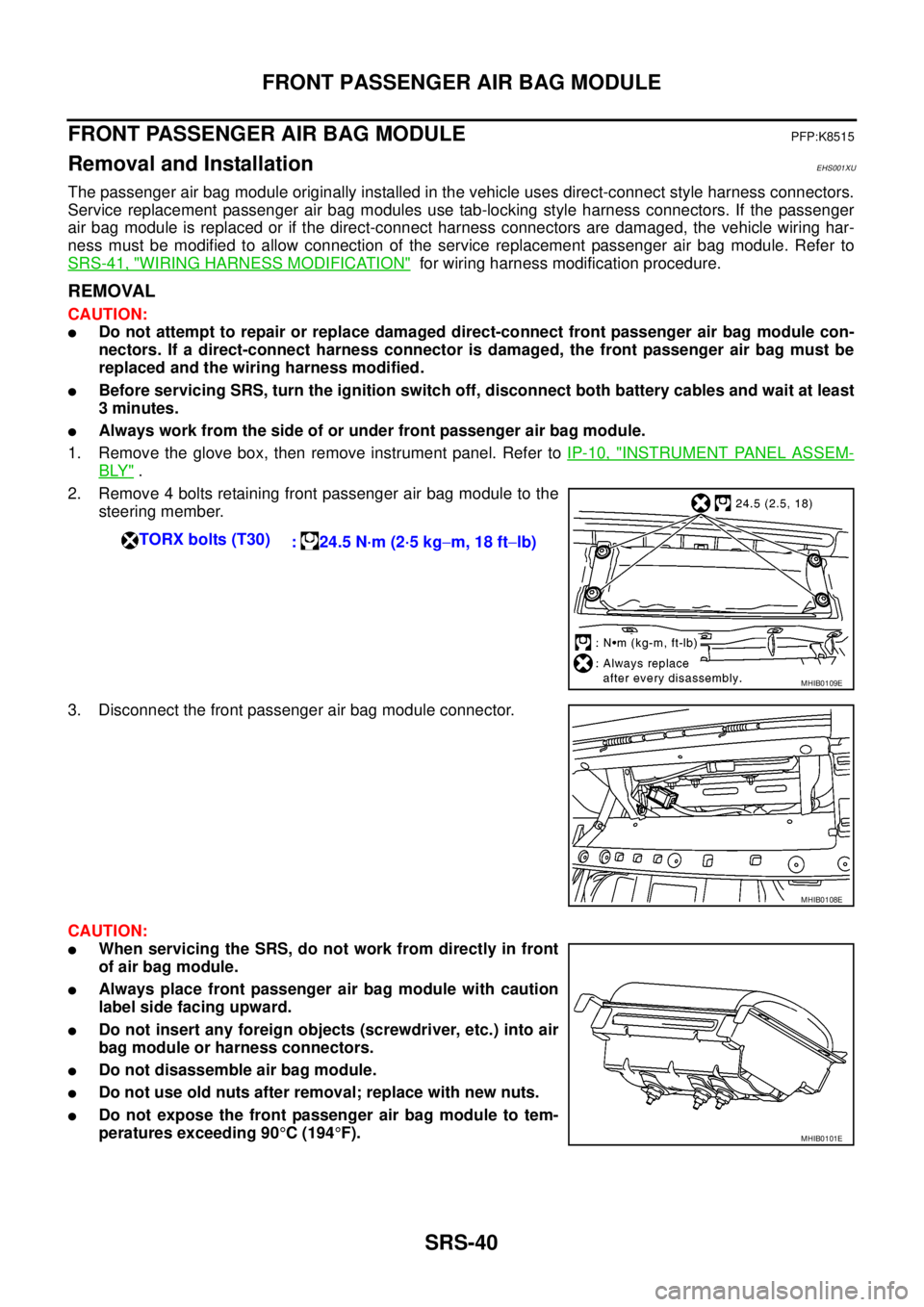
1. Remove the glove box, then remove instrument panel. Refer toIP-10, "
INSTRUMENT PANEL ASSEM-
BLY".
2. Remove 4 bolts retaining front passenger air bag module to the
steering member.
3. Disconnect the front passenger air bag module connector.
CAUTION:
lWhen servicing the SRS, do not work from directly in front
of air bag module.
lAlways place front passenger air bag module with caution
label side facing upward.
lDo not insert any foreign objects (screwdriver, etc.) into air
bag module or harness connectors.
lDo not disassemble air bag module.
lDo not use old nuts after removal; replace with new nuts.
lDo not expose the front passenger air bag module to tem-
peratures exceeding 90°C(194°F). TORX bolts (T30)
: 24.5 N·m (2·5 kg-m, 18 ft-lb)
MHIB0109E
MHIB0108E
MHIB0101E
Page 2950 of 3171
FRONT PASSENGER AIR BAG MODULE
SRS-41
C
D
E
F
G
I
J
K
L
MA
B
SRS
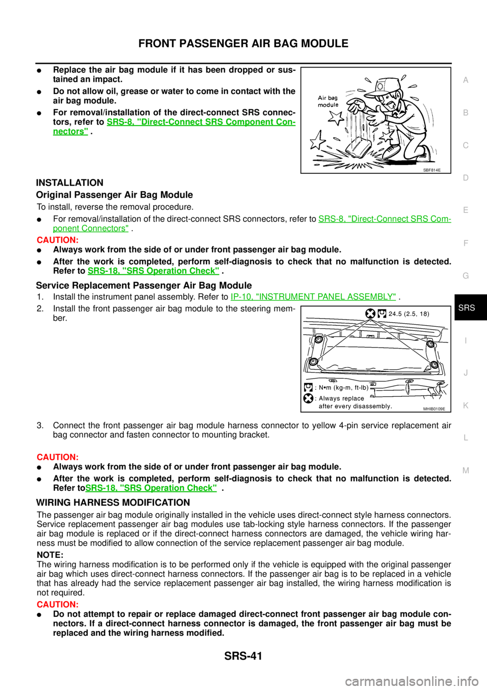
lReplace the air bag module if it has been dropped or sus-
tainedanimpact.
lDo not allow oil, grease or water to come in contact with the
air bag module.
lFor removal/installation of the direct-connect SRS connec-
tors, refer toSRS-8, "
Direct-Connect SRS Component Con-
nectors".
INSTALLATION
Original Passenger Air Bag Module
To install, reverse the removal procedure.
lFor removal/installation of the direct-connect SRS connectors, refer toSRS-8, "Direct-Connect SRS Com-
ponent Connectors".
CAUTION:
lAlways work from the side of or under front passenger air bag module.
lAfter the work is completed, perform self-diagnosis to check that no malfunction is detected.
Refer toSRS-18, "
SRS Operation Check".
Service Replacement Passenger Air Bag Module
1. Install the instrument panel assembly. Refer toIP-10, "INSTRUMENT PANEL ASSEMBLY".
2. Install the front passenger air bag module to the steering mem-
ber.
3. Connect the front passenger air bag module harness connector to yellow 4-pin service replacement air
bag connector and fasten connector to mounting bracket.
CAUTION:
lAlways work from the side of or under front passenger air bag module.
lAfter the work is completed, perform self-diagnosis to check that no malfunction is detected.
Refer toSRS-18, "
SRS Operation Check".
WIRING HARNESS MODIFICATION
The passenger air bag module originally installed in the vehicle uses direct-connect style harness connectors.
Service replacement passenger air bag modules use tab-locking style harness connectors. If the passenger
air bag module is replaced or if the direct-connect harness connectors are damaged, the vehicle wiring har-
ness must be modified to allow connection of the service replacement passenger air bag module.
NOTE:
The wiring harness modification is to be performed only if the vehicle is equipped with the original passenger
air bag which uses direct-connect harness connectors. If the passenger air bag is to be replaced in a vehicle
that has already had the service replacement passenger air bag installed, the wiring harness modification is
not required.
CAUTION:
lDo not attempt to repair or replace damaged direct-connect front passenger air bag module con-
nectors. If a direct-connect harness connector is damaged, the front passenger air bag must be
replaced and the wiring harness modified.
SBF814E
MHIB0109E