2005 NISSAN NAVARA steering
[x] Cancel search: steeringPage 2287 of 3171
MA-12
PERIODIC MAINTENANCE
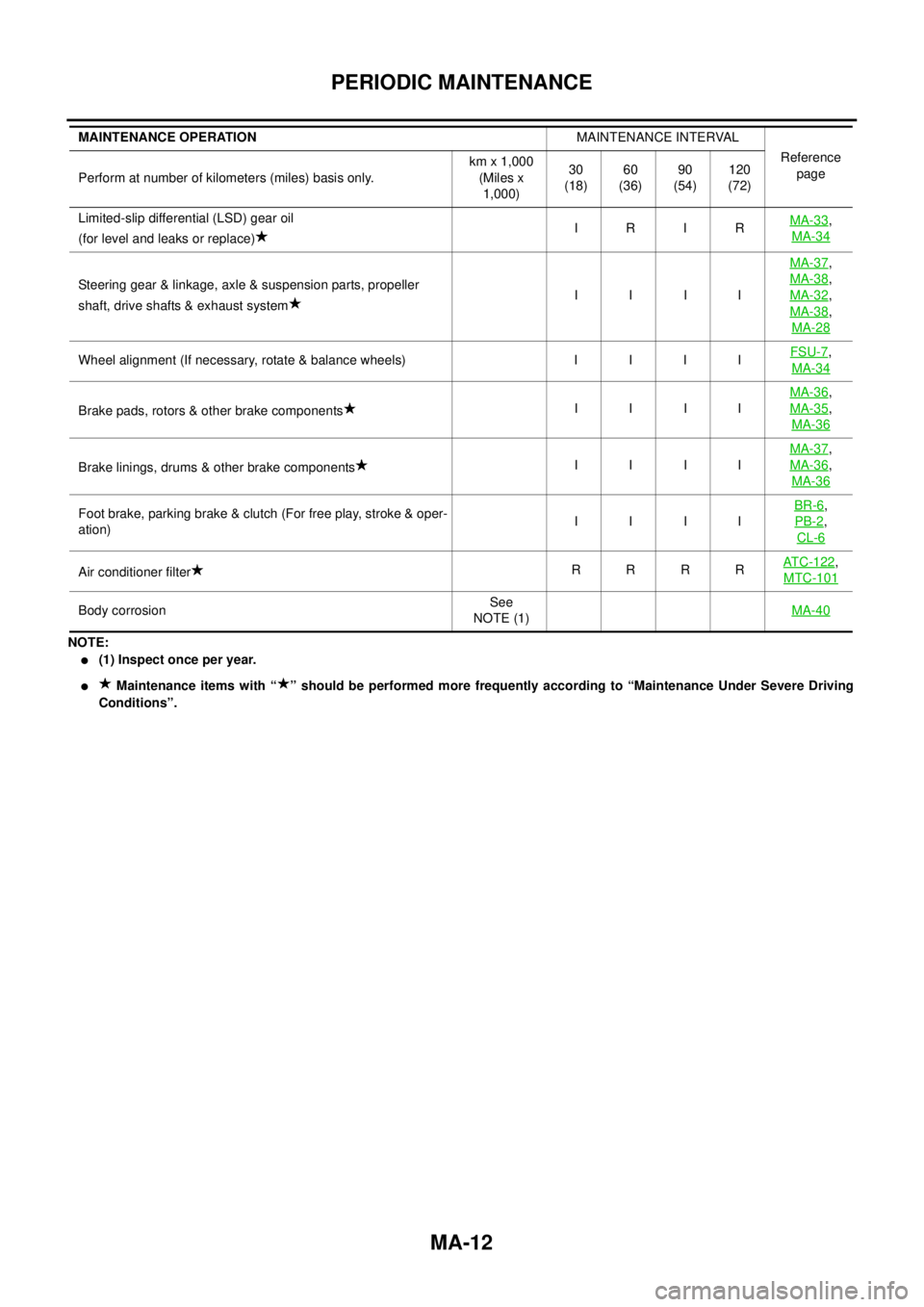
NOTE:
l(1) Inspect once per year.
lMaintenance items with “ ” should be performed more frequently according to “Maintenance Under Severe Driving
Conditions”. Limited-slip differential (LSD) gear oil
(for level and leaks or replace)IRIRMA-33
,
MA-34
Steering gear & linkage, axle & suspension parts, propeller
shaft, drive shafts & exhaust systemIIIIMA-37
,
MA-38
,
MA-32
,
MA-38
,
MA-28
Wheel alignment (If necessary, rotate & balance wheels) I I I IFSU-7,
MA-34
Brake pads, rotors & other brake componentsIIIIMA-36
,
MA-35
,
MA-36
Brake linings, drums & other brake componentsIIIIMA-37
,
MA-36
,
MA-36
Foot brake, parking brake & clutch (For free play, stroke & oper-
ation)IIIIBR-6,
PB-2
,
CL-6
Air conditioner filterRRRRAT C - 1 2 2,
MTC-101
Body corrosionSee
NOTE (1)MA-40
MAINTENANCE OPERATIONMAINTENANCE INTERVAL
Reference
page
Perform at number of kilometers (miles) basis only.km x 1,000
(Miles x
1,000)30
(18)60
(36)90
(54)120
(72)
Page 2288 of 3171
PERIODIC MAINTENANCE
MA-13
C
D
E
F
G
H
I
J
K
MA
B
MA
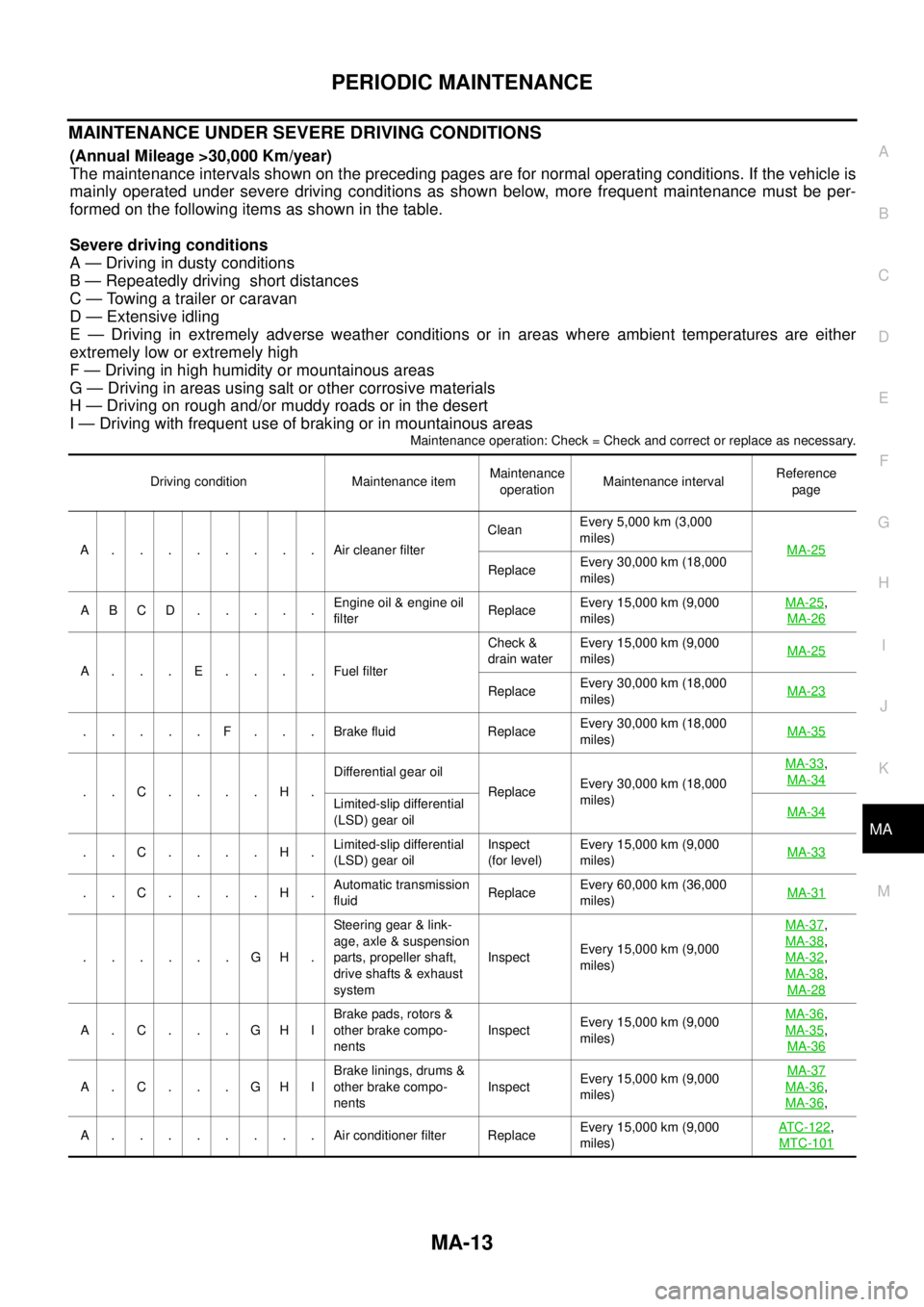
MAINTENANCE UNDER SEVERE DRIVING CONDITIONS
(Annual Mileage >30,000 Km/year)
The maintenance intervals shown on the preceding pages are for normal operating conditions. If the vehicle is
mainly operated under severe driving conditions as shown below, more frequent maintenance must be per-
formed on the following items as shown in the table.
Severe driving conditions
A — Driving in dusty conditions
B — Repeatedly driving short distances
C — Towing a trailer or caravan
D — Extensive idling
E — Driving in extremely adverse weather conditions or in areas where ambient temperatures are either
extremely low or extremely high
F — Driving in high humidity or mountainous areas
G — Driving in areas using salt or other corrosive materials
H — Driving on rough and/or muddy roads or in the desert
I — Driving with frequent use of braking or in mountainous areas
Maintenance operation: Check = Check and correct or replace as necessary.
Driving condition Maintenance itemMaintenance
operationMaintenance intervalReference
page
A........Aircleaner filterCleanEvery 5,000 km (3,000
miles)
MA-25
ReplaceEvery 30,000 km (18,000
miles)
ABCD.....Engine oil & engine oil
filterReplaceEvery 15,000 km (9,000
miles)MA-25
,
MA-26
A...E....FuelfilterCheck &
drain waterEvery 15,000 km (9,000
miles)MA-25
ReplaceEvery 30,000 km (18,000
miles)MA-23
.....F...Brakefluid ReplaceEvery 30,000 km (18,000
miles)MA-35
..C....H.Differential gear oil
ReplaceEvery 30,000 km (18,000
miles)MA-33
,
MA-34
Limited-slip differential
(LSD) gear oilMA-34
..C....H.Limited-slip differential
(LSD) gear oilInspect
(for level)Every 15,000 km (9,000
miles)MA-33
..C....H.Automatic transmission
fluidReplaceEvery 60,000 km (36,000
miles)MA-31
......GH.Steering gear & link-
age, axle & suspension
parts, propeller shaft,
drive shafts & exhaust
systemInspectEvery 15,000 km (9,000
miles)MA-37
,
MA-38
,
MA-32
,
MA-38
,
MA-28
A.C...GHIBrake pads, rotors &
other brake compo-
nentsInspectEvery 15,000 km (9,000
miles)MA-36
,
MA-35
,
MA-36
A.C...GHIBrake linings, drums &
other brake compo-
nentsInspectEvery 15,000 km (9,000
miles)MA-37MA-36,
MA-36
,
A........Airconditioner filter ReplaceEvery 15,000 km (9,000
miles)ATC-122
,
MTC-101
Page 2289 of 3171

MA-14
RECOMMENDED FLUIDS AND LUBRICANTS
RECOMMENDED FLUIDS AND LUBRICANTS
PFP:00000
Fluids and LubricantsELS001JA
*1: For further details, see “SAE Viscosity Number”.
*2: Never use API CG-4.
*3: Use Genuine NISSAN Anti-freeze Coolant (L250) or equivalent in its quality, in order to avoid possible aluminum corrosion within the
engine cooling system caused by the use of non-genuine engine coolant.
Note that any repairs for the incidents within the engine cooling system while using non-genuine engine coolant may not be
covered by the warranty even if such incidents occurred during the warranty period.
*4: Contact a Nissan dealership for more information regarding suitable fluids, including recommended brand(s) of DEXRON
™III/MER-
CON™ Automatic Transmission Fluid.
*5:Using automatic transmission fluid other than Genuine NISSAN ATF Matic Fluid J will cause deterioration in driveability
and automatic transmission durability, and may damage the automatic transmission, which is not covered by the warranty.
*6: DEXRON™III type ATF can be used.
*7: Never mix different types of fluids (DOT 3 and DOT 4).Capacity (Approximate)
Recommended Fluids/Lubricants
Liter Imp measure
Engine oil
Drain and refillWith oil filter change 7.6 6-5/8 qt
lDiesel engine
API CF-4*1, *2
ACEA B1, B3, B4, B5*1 Without oil filter change 7.1 6-1/4 qt
Dry engine (engine overhaul) 7.9 7 qt
Cooling sys-
tem (with res-
ervoir)LHD models 9.9 8-3/4 qt
lGenuine NISSAN Anti-freeze Coolant (L250) or
equivalent in its quality*3 RHD models 10.2 9 qt
Reservoir tank 0.8 3/4 qt
Manual transmission gear oil2WD 3.99 7 pt
lGenuine NISSAN gear oil or API GL-4, Viscosity
SAE 75W-85 or 75W-90
4WD 4.32 7-5/8 pt
Transfer fluid 2.0 1-3/4 qt
lGenuine NISSAN ATF or equivalent*4
Differential gear oilFront 0.85 1-1/2 pt
lStandard differential gear:
Gear Oil Hypoid LSD (Part No.: KLD31-8090403)
or API GL-5, Viscosity SAE 80W-90*1
lLimited-slip differential (LSD) gear:
Gear Oil Hypoid LSD (Part No. KLD31-8090403)
or equivalent Rear 2.01 3-1/2 pt
Automatic transmission fluid 10.3 9-1/8 qt Genuine NISSAN ATF Matic Fluid J*5
Power steering fluid — — Genuine NISSAN PSF or equivalent*6
Brake and clutch fluid — —
lDOT 3 or DOT 4 (US FMVSS No. 116)*7
Multi-purpose grease — — NLGI No. 2 (Lithium soap base)
Page 2292 of 3171
ENGINE MAINTENANCE
MA-17
C
D
E
F
G
H
I
J
K
MA
B
MA
ENGINE MAINTENANCEPFP:00000
Checking Drive BeltsELS001JO
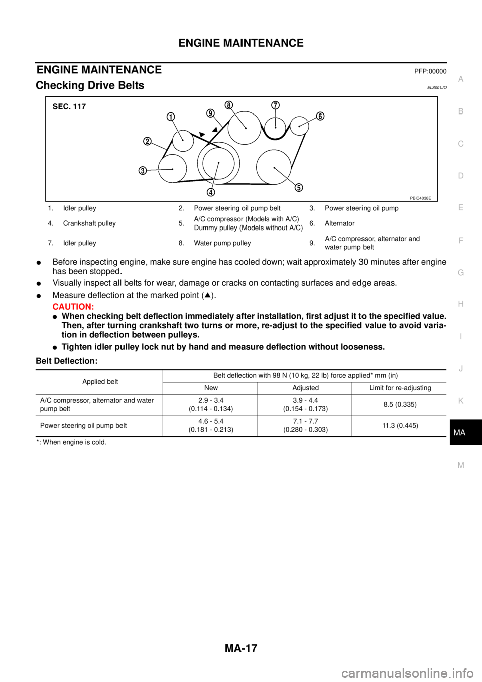
lBefore inspecting engine, make sure engine has cooled down; wait approximately 30 minutes after engine
has been stopped.
lVisually inspect all belts for wear, damage or cracks on contacting surfaces and edge areas.
lMeasure deflection at the marked point ( ).
CAUTION:
lWhen checking belt deflection immediately after installation, first adjust it to the specified value.
Then, after turning crankshaft two turns or more, re-adjust to the specified value to avoid varia-
tion in deflection between pulleys.
lTighten idler pulley lock nut by hand and measure deflection without looseness.
Belt Deflection:
*: When engine is cold.1. Idler pulley 2. Power steering oil pump belt 3. Power steering oil pump
4. Crankshaft pulley 5.A/C compressor (Models with A/C)
Dummy pulley (Models without A/C)6. Alternator
7. Idler pulley 8. Water pump pulley 9.A/C compressor, alternator and
water pump belt
PBIC4038E
Applied beltBelt deflection with 98 N (10 kg, 22 lb) force applied* mm (in)
New Adjusted Limit for re-adjusting
A/C compressor, alternator and water
pump belt2.9 - 3.4
(0.114 - 0.134)3.9 - 4.4
(0.154 - 0.173)8.5 (0.335)
Power steering oil pump belt4.6 - 5.4
(0.181 - 0.213)7.1 - 7.7
(0.280 - 0.303)11.3 (0.445)
Page 2293 of 3171
MA-18
ENGINE MAINTENANCE
Deflection Adjustment
ELS001JP
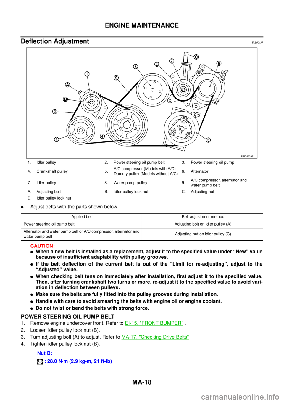
lAdjust belts with the parts shown below.
CAUTION:
lWhen a new belt is installed as a replacement, adjust it to the specified value under “New” value
because of insufficient adaptability with pulley grooves.
lIf the belt deflection of the current belt is out of the “Limit for re-adjusting”, adjust to the
“Adjusted” value.
lWhen checking belt tension immediately after installation, first adjust it to the specified value.
Then, after turning crankshaft two turns or more, re-adjust it to the specified value to avoid vari-
ation in deflection between pulleys.
lMake sure the belts are fully fitted into the pulley grooves during installation.
lHandle with care to avoid smearing the belts with engine oil or engine coolant.
lDo not twist or bend the belts with strong force.
POWER STEERING OIL PUMP BELT
1. Remove engine undercover front. Refer toEI-15, "FRONT BUMPER".
2. Loosen idler pulley lock nut (B).
3. Turn adjusting bolt (A) to adjust. Refer toMA-17, "
Checking Drive Belts".
4. Tighten idler pulley lock nut (B).
1. Idler pulley 2. Power steering oil pump belt 3. Power steering oil pump
4. Crankshaft pulley 5.A/C compressor (Models with A/C)
Dummypulley(ModelswithoutA/C)6. Alternator
7. Idler pulley 8. Water pump pulley 9.A/C compressor, alternator and
water pump belt
A. Adjusting bolt B. Idler pulley lock nut C. Adjusting nut
D. Idler pulley lock nut
PBIC4039E
Applied belt Belt adjustment method
Power steering oil pump belt Adjusting bolt on idler pulley (A)
Alternator and water pump belt or A/C compressor, alternator and
water pump beltAdjusting nut on idler pulley (C)
Nut B:
: 28.0 N·m (2.9 kg-m, 21 ft-lb)
Page 2312 of 3171
CHASSIS AND BODY MAINTENANCE
MA-37
C
D
E
F
G
H
I
J
K
MA
B
MA
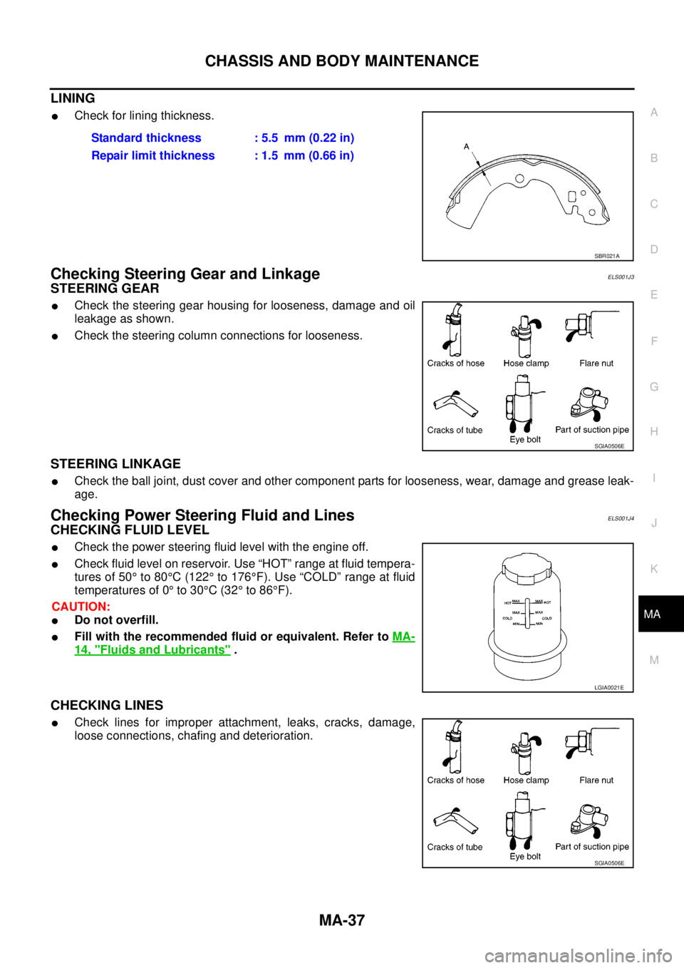
LINING
lCheck for lining thickness.
Checking Steering Gear and LinkageELS001J3
STEERING GEAR
lCheck the steering gear housing for looseness, damage and oil
leakage as shown.
lCheck the steering column connections for looseness.
STEERING LINKAGE
lCheck the ball joint, dust cover and other component parts for looseness, wear, damage and grease leak-
age.
Checking Power Steering Fluid and LinesELS001J4
CHECKING FLUID LEVEL
lCheck the power steering fluid level with the engine off.
lCheck fluid level on reservoir. Use “HOT” range at fluid tempera-
tures of 50°to 80°C(122°to 176°F). Use “COLD” range at fluid
temperatures of 0°to 30°C(32°to 86°F).
CAUTION:
lDo not overfill.
lFill with the recommended fluid or equivalent. Refer toMA-
14, "Fluids and Lubricants".
CHECKING LINES
lCheck lines for improper attachment, leaks, cracks, damage,
loose connections, chafing and deterioration.Standard thickness : 5.5 mm (0.22 in)
Repair limit thickness : 1.5 mm (0.66 in)
SBR021A
SGIA0506E
LGIA0021E
SGIA0506E
Page 2316 of 3171

SERVICE DATA AND SPECIFICATIONS (SDS)
MA-41
C
D
E
F
G
H
I
J
K
MA
B
MA
SERVICE DATA AND SPECIFICATIONS (SDS)PFP:00030
Standard and LimitELS001J8
BELT DEFLECTION
*: When engine is cold.
RESERVOIR TANK
Unit:kPa(bar,kg/cm2, psi)
ENGINE COOLANT CAPACITY (APPROXIMATE)
Unit: (lmp qt)
ENGINE OIL CAPACITY (APPROXIMATE)
Unit: (lmp qt) Applied beltBelt deflection with 98 N (10 kg, 22 lb) force applied* mm (in)
New Adjusted Limit for re-adjusting
A/C compressor, alternator and water
pump belt2.9 - 3.4 (0.114 - 0.134) 3.9 - 4.4 (0.154 - 0.173) 8.5 (0.335)
Power steering oil pump belt 4.6 - 5.4 (0.181 - 0.213) 7.1 - 7.7 (0.280 - 0.303) 11.3 (0.445)
Cap relief pressureStandard 98.2 - 117.8 (0.98 - 1.18, 1.0 - 1.2, 14 - 17)
Limit 59 (0.59, 0.6, 9)
Leakage test pressure 157 (1.57, 1.6, 23)
Engine coolant capacity (With reser-
voir tank at “MAX” level)LHD models 9.9 (8-3/4)
RHD models 10.2 (9)
Reservoir tank coolant capacity (At “MAX” level) 0.8 (3/4)
Drain and refillWith oil filter change 7.6 (6-5/8)
Without oil filter change 7.1 (6-1/4)
Dry engine (Overhaul)7.9 (7)
Page 2492 of 3171
HEATER & COOLING UNIT ASSEMBLY
MTC-105
C
D
E
F
G
H
I
K
L
MA
B
MTC
Removal and InstallationEJS005GY
REMOVAL
1. Discharge the refrigerant from the A/C system. Refer toMTC-118, "Discharging Refrigerant".
2. Drain the coolant from the engine cooling system. Refer toCO-8, "
DRAINING ENGINE COOLANT".
3. Remove the cowl top extension. Refer toEI-20, "
Removal and Installation".
4. Remove the exhaust system. Refer toEX-3, "
Removal and Installation".
5. Disconnect the heater hoses from the heater core.
6. Disconnect the high/low pressure pipes from the expansion valve.
7. Move the two front seats to the rearmost position on the seat track.
8. Remove the instrument panel and console panel. Refer toIP-10, "
Removal and Installation".
9. Remove the steering column. Refer toPS-11, "
Removal and Installation".
10. Disconnect the instrument panel wire harness at the RH and LH in-line connector brackets, and the fuse
block (J/B) electrical connectors. Refer toPG-38, "
Harness Layout".
11. Disconnect the steering member from each side of the vehicle body.
12. Remove the heater and cooling unit assembly with it attached to the steering member, from the vehicle.
CAUTION:
Use care not to damage the seats and interior trim panels when removing the heater and cooling
unit assembly with it attached to the steering member.
13. Remove the heater and cooling unit assembly from the steering member.
INSTALLATION
Installation is in the reverse order of removal.
CAUTION:
lReplace the O-ring of the low-pressure pipe and high-pressure pipe with a new one, and apply
compressor oil to it when installing it.
lAfter charging the refrigerant, check for leaks.
NOTE:
lFill the engine cooling system with the specified coolant mixture. Refer toCO-8, "REFILLING ENGINE
COOLANT".
lRecharge the A/C system. Refer toMTC-118, "Evacuating System and Charging Refrigerant".