2005 NISSAN NAVARA steering
[x] Cancel search: steeringPage 791 of 3171

NOISE, VIBRATION AND HARSHNESS (NVH) TROUBLESHOOTING
BR-5
C
D
E
G
H
I
J
K
L
MA
B
BR
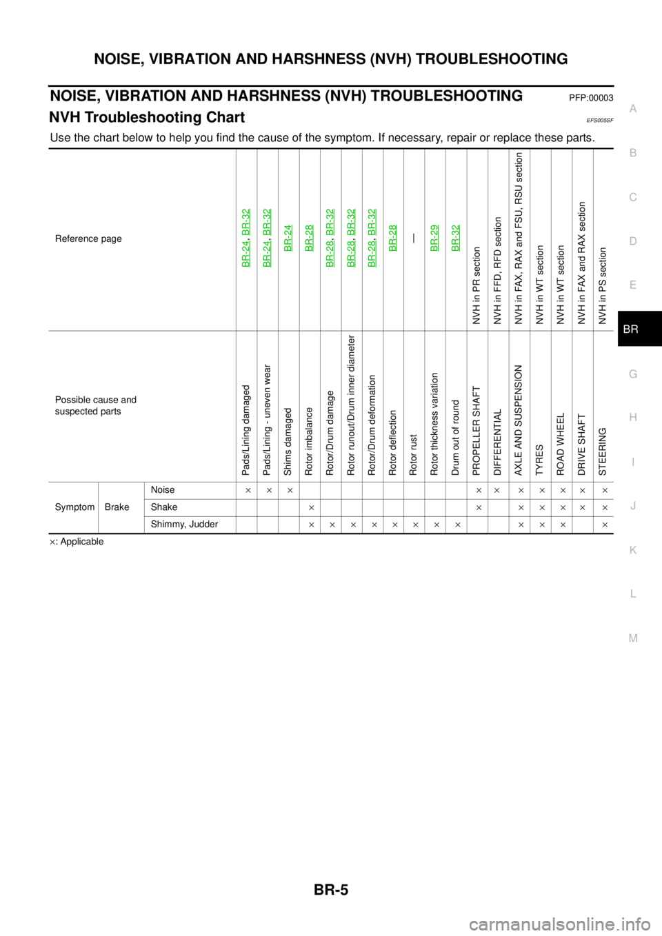
NOISE, VIBRATION AND HARSHNESS (NVH) TROUBLESHOOTINGPFP:00003
NVH Troubleshooting ChartEFS005SF
Use the chart below to help you find the cause of the symptom. If necessary, repair or replace these parts.
´: Applicable Reference page
BR-24
,BR-32
BR-24
,BR-32BR-24BR-28
BR-28
,BR-32
BR-28
,BR-32
BR-28
,BR-32BR-28—
BR-29BR-32
NVHinPRsection
NVH in FFD, RFD section
NVH in FAX, RAX and FSU, RSU section
NVH in WT section
NVH in WT section
NVH in FAX and RAX section
NVH in PS section
Possible cause and
suspected parts
Pads/Lining damaged
Pads/Lining - uneven wear
Shims damaged
Rotor imbalance
Rotor/Drum damage
Rotor runout/Drum inner diameter
Rotor/Drum deformation
Rotor deflection
Rotor rust
Rotor thickness variation
Drum out of round
PROPELLER SHAFT
DIFFERENTIAL
AXLE AND SUSPENSION
TYRES
ROAD WHEEL
DRIVE SHAFT
STEERING
Symptom BrakeNoise´´´ ´´ ´´´
´´
Shake´´´´´
´´
Shimmy, Judder´´´´´´´´ ´´´ ´
Page 799 of 3171

BRAKE TUBE AND HOSE
BR-13
C
D
E
G
H
I
J
K
L
MA
B
BR
CAUTION:
lAll brake tubes and hoses must be free from excessive bending, twisting and pulling.
lMake sure that there is no interference with other parts when turning steering both clockwise and
counterclockwise.
lBrake tube and hose is an important safety part. Always disassemble the parts and retighten their
fittings, if a brake fluid leak is detected. Replace applicable part with a new one, if damaged part is
detected.
lBe careful not to splash brake fluid on painted areas; it may cause paint damage. If brake fluid is
splashed on painted surfaces of body, immediately wipe off them and wash it away with water.
lDo not bend or twist brake hose sharply, or strongly pull it.
lCover the open end of brake tube and hoses when disconnecting to prevent entrance of dirt.
lRefill with new brake fluid “DOT 3” or “DOT 4”.
lNever reuse drained brake fluid.
Removal and Installation of Front Brake Tube and Brake HoseEFS005SM
REMOVAL
1. Drain brake fluid. Refer toBR-10, "Drain and Refill".
2. Using a flare nut wrench, disconnect brake tube from brake hose.
3. Remove union bolt and remove brake hose from caliper assembly.
4. Remove lock plate and remove brake hose from vehicle.
INSTALLATION
1. Assemble the union bolt and copper washers to the brake hose.
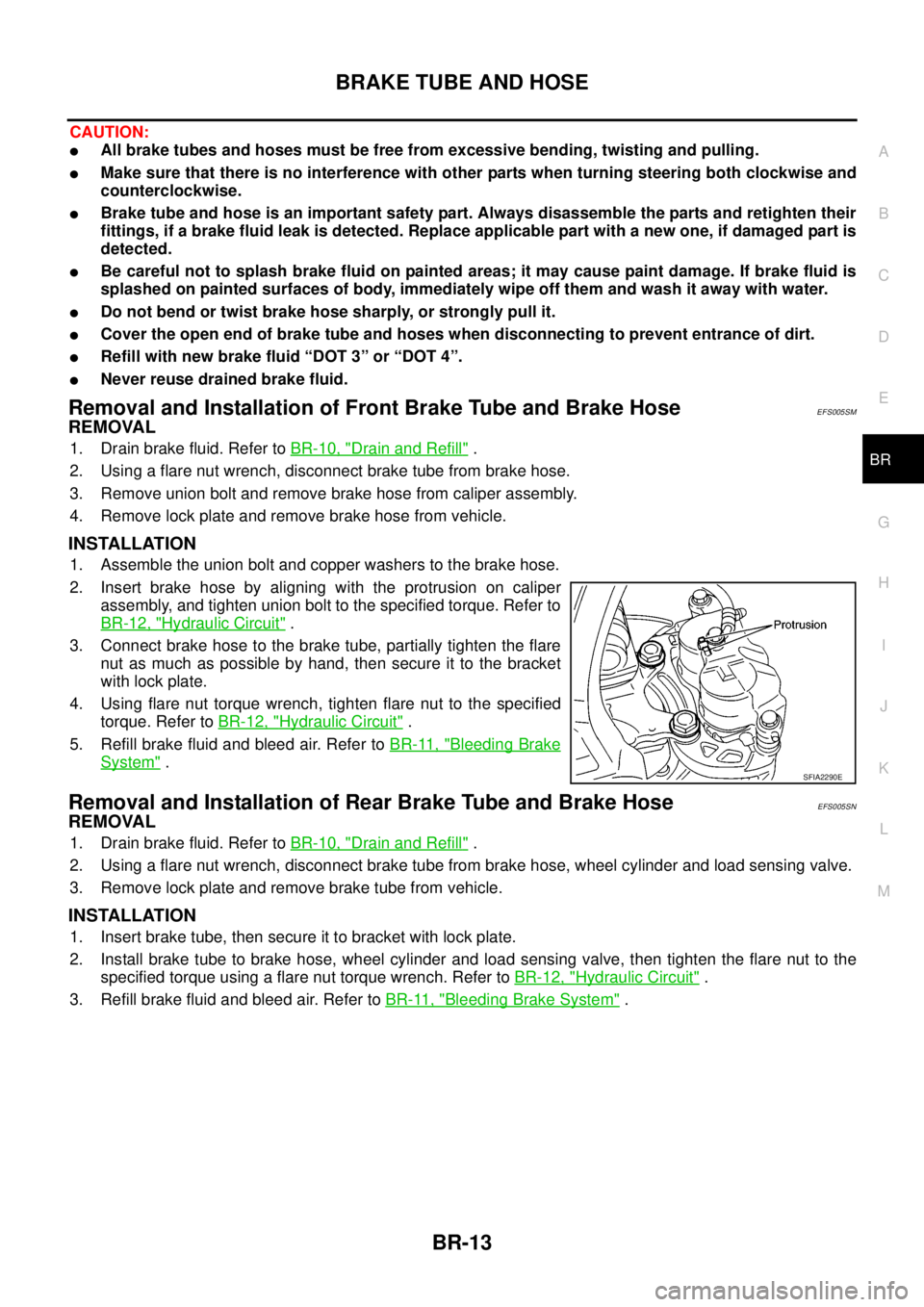
2. Insert brake hose by aligning with the protrusion on caliper
assembly, and tighten union bolt to the specified torque. Refer to
BR-12, "
Hydraulic Circuit".
3. Connect brake hose to the brake tube, partially tighten the flare
nut as much as possible by hand, then secure it to the bracket
with lock plate.
4. Using flare nut torque wrench, tighten flare nut to the specified
torque. Refer toBR-12, "
Hydraulic Circuit".
5. Refill brake fluid and bleed air. Refer toBR-11, "
Bleeding Brake
System".
Removal and Installation of Rear Brake Tube and Brake HoseEFS005SN
REMOVAL
1. Drain brake fluid. Refer toBR-10, "Drain and Refill".
2. Using a flare nut wrench, disconnect brake tube from brake hose, wheel cylinder and load sensing valve.
3. Remove lock plate and remove brake tube from vehicle.
INSTALLATION
1. Insert brake tube, then secure it to bracket with lock plate.
2. Install brake tube to brake hose, wheel cylinder and load sensing valve, then tighten the flare nut to the
specified torque using a flare nut torque wrench. Refer toBR-12, "
Hydraulic Circuit".
3. Refill brake fluid and bleed air. Refer toBR-11, "
Bleeding Brake System".
SFIA2290E
Page 812 of 3171

BR-26
FRONT DISC BRAKE
Removal and Installation of Brake Caliper Assembly
EFS005T1
REMOVAL
1. Remove tyre from vehicle.
2. Fasten disc rotor using wheel nut.
CAUTION:
Align the matching marks of disc rotor and wheel hub, which were marked at the time of removal
when reusing disc rotor.
3. Drain brake fluid. Refer toBR-10, "
Drain and Refill".
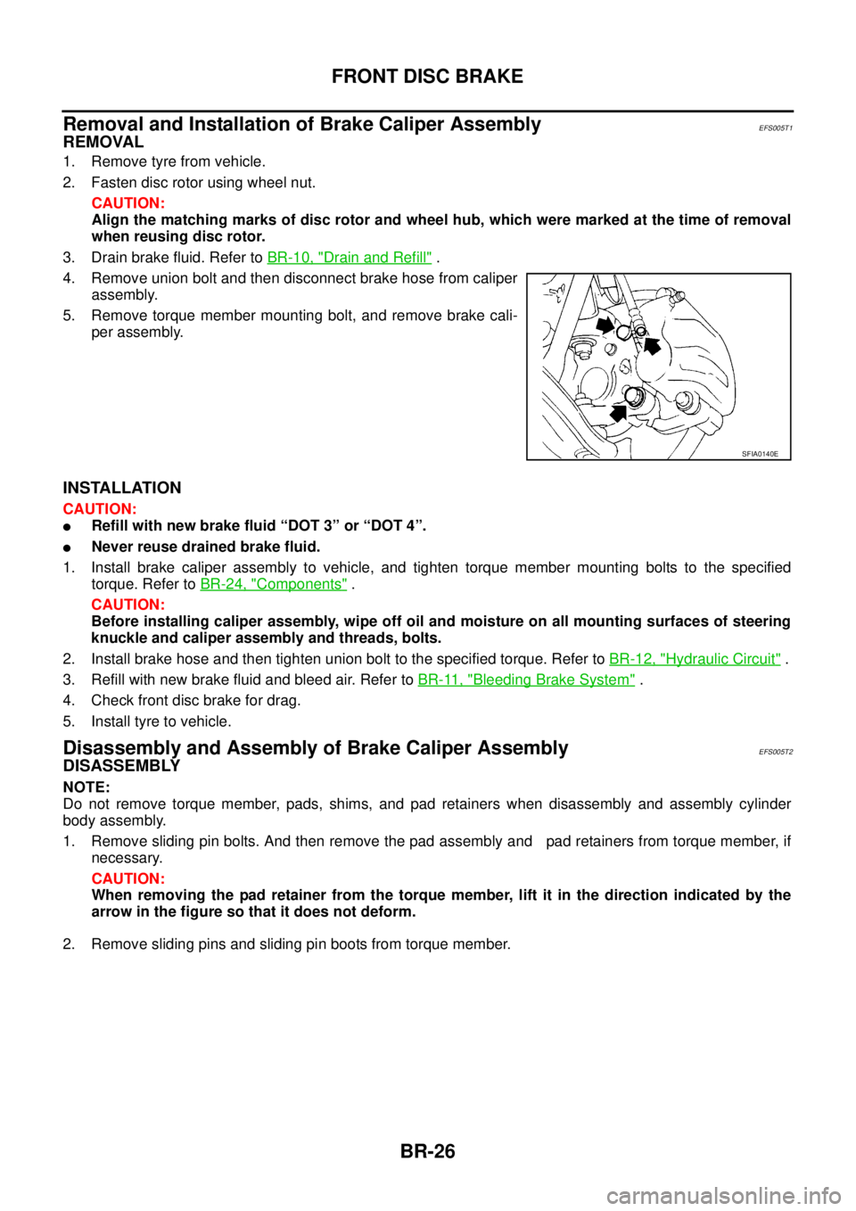
4. Remove union bolt and then disconnect brake hose from caliper
assembly.
5. Remove torque member mounting bolt, and remove brake cali-
per assembly.
INSTALLATION
CAUTION:
lRefill with new brake fluid “DOT 3” or “DOT 4”.
lNever reuse drained brake fluid.
1. Install brake caliper assembly to vehicle, and tighten torque member mounting bolts to the specified
torque. Refer toBR-24, "
Components".
CAUTION:
Before installing caliper assembly, wipe off oil and moisture on all mounting surfaces of steering
knuckle and caliper assembly and threads, bolts.
2. Install brake hose and then tighten union bolt to the specified torque. Refer toBR-12, "
Hydraulic Circuit".
3. Refill with new brake fluid and bleed air. Refer toBR-11, "
Bleeding Brake System".
4. Check front disc brake for drag.
5. Install tyre to vehicle.
Disassembly and Assembly of Brake Caliper AssemblyEFS005T2
DISASSEMBLY
NOTE:
Do not remove torque member, pads, shims, and pad retainers when disassembly and assembly cylinder
body assembly.
1. Remove sliding pin bolts. And then remove the pad assembly and pad retainers from torque member, if
necessary.
CAUTION:
When removing the pad retainer from the torque member, lift it in the direction indicated by the
arrow in the figure so that it does not deform.
2. Remove sliding pins and sliding pin boots from torque member.
SFIA0140E
Page 825 of 3171
![NISSAN NAVARA 2005 Repair Workshop Manual PRECAUTIONS
BRC-3
[ABS]
C
D
E
G
H
I
J
K
L
MA
B
BRC
[ABS]PRECAUTIONSPFP:00001
Precautions for Supplemental Restraint System (SRS) “AIR BAG” and “SEAT
BELT PRE-TENSIONER”
EFS006DM
The Supplement NISSAN NAVARA 2005 Repair Workshop Manual PRECAUTIONS
BRC-3
[ABS]
C
D
E
G
H
I
J
K
L
MA
B
BRC
[ABS]PRECAUTIONSPFP:00001
Precautions for Supplemental Restraint System (SRS) “AIR BAG” and “SEAT
BELT PRE-TENSIONER”
EFS006DM
The Supplement](/manual-img/5/57362/w960_57362-824.png)
PRECAUTIONS
BRC-3
[ABS]
C
D
E
G
H
I
J
K
L
MA
B
BRC
[ABS]PRECAUTIONSPFP:00001
Precautions for Supplemental Restraint System (SRS) “AIR BAG” and “SEAT
BELT PRE-TENSIONER”
EFS006DM
The Supplemental Restraint System such as “AIR BAG” and “SEAT BELT PRE-TENSIONER”, used along
with a front seat belt, helps to reduce the risk or severity of injury to the driver and front passenger for certain
types of collision. Information necessary to service the system safely is included in the SRS and SB section of
this Service Manual.
WARNING:
lTo avoid rendering the SRS inoperative, which could increase the risk of personal injury or death
in the event of a collision which would result in air bag inflation, all maintenance must be per-
formed by an authorized NISSAN/INFINITI dealer.
lImproper maintenance, including incorrect removal and installation of the SRS, can lead to per-
sonal injury caused by unintentional activation of the system. For removal of Spiral Cable and Air
Bag Module, see the SRS section.
lDo not use electrical test equipment on any circuit related to the SRS unless instructed to in this
Service Manual. SRS wiring harnesses can be identified by yellow and/or orange harnesses or
harness connectors.
Precautions for Brake SystemEFS005TG
lRecommended fluid is brake fluid “DOT 3” or “DOT 4”.
lNever reuse drained brake fluid.
lBe careful not to splash brake fluid on painted areas.If brake fluid is splashed, wipe it off and flush area
with water immediately.
lNever use mineral oils such as gasoline or kerosene. They will ruin rubber parts of the hydraulic system.
lUse flare nut wrench when removing flare nuts, and use a flare
nut torque wrench when tighten flare nuts.
lBrake system is an important safety part.If a brake fluid leak is
detected, always disassemble the affected part.If a malfunction
is detected, replace part with new one.
lBefore working, turn ignition switch OFF and disconnect con-
nector of ABS actuator and electric unit (control unit) or the bat-
tery cables.
lWhen installing brake tube and hose, be sure to torque.
WARNING:
Clean brake pads and shoes with a waster cloth, then wipe with
a dust collector.
Precautions for Brake ControlEFS005TH
lJust after starting vehicle after ignition switch ON, brake pedal may vibrate or motor operating noise may
be heard from engine room. This is a normal status of operation check.
lStopping distance may be longer than that of vehicles without ABS when vehicle drives on rough, gravel,
or snow-covered (fresh, deep snow) roads.
lWhen an error is indicated by ABS or another warning lamp, collect all necessary information from cus-
tomer (what symptoms are present under what conditions) and check for simple causes before starting
diagnostic servicing. Besides electrical system inspection, check brake booster operation, brake fluid
level, and fluid leaks.
lIf tyre size and type are used in an improper combination, or brake pads are not Genuine NISSAN parts,
stopping distance or steering stability may deteriorate.
lIf there is a radio, antenna, or antenna lead-in wire (including wiring) near control module, ABS function
may have a malfunction or error.
lIf aftermarket parts (car stereo, CD player, etc.) have been installed, check for incidents such as harness
pinches, open circuits, and improper wiring.
SBR820BA
Page 847 of 3171
![NISSAN NAVARA 2005 Repair Workshop Manual TROUBLE DIAGNOSIS
BRC-25
[ABS]
C
D
E
G
H
I
J
K
L
MA
B
BRC
3.CHECK SENSOR AND SENSOR ROTOR
lCheck sensor rotor for damage.
lCheck wheel sensor for damage, disconnection or looseness.
OK or NG
OK >> GO NISSAN NAVARA 2005 Repair Workshop Manual TROUBLE DIAGNOSIS
BRC-25
[ABS]
C
D
E
G
H
I
J
K
L
MA
B
BRC
3.CHECK SENSOR AND SENSOR ROTOR
lCheck sensor rotor for damage.
lCheck wheel sensor for damage, disconnection or looseness.
OK or NG
OK >> GO](/manual-img/5/57362/w960_57362-846.png)
TROUBLE DIAGNOSIS
BRC-25
[ABS]
C
D
E
G
H
I
J
K
L
MA
B
BRC
3.CHECK SENSOR AND SENSOR ROTOR
lCheck sensor rotor for damage.
lCheck wheel sensor for damage, disconnection or looseness.
OK or NG
OK >> GO TO 4.
NG >> Repair or replace the malfunctioning component.
4.CHECK CONNECTOR
1. Turn ignition switch OFF and disconnect ABS actuator and electric unit (control unit) connector E63 and
malfunctioning wheel sensor connector E66 (FR - LH), E77 (FR - RH), C10 (RR - LH) or C11 (RR - RH).
Check terminal to see if it is deformed, disconnected, loose, etc., and repair or replace it if any malfunction
condition is found.
2. Reconnect connectors and check that interference with other parts has not cut wheel sensor cables, drive
vehicle at 30 km/h (19 MPH) or more for approximately 1minute, and perform self-diagnosis.
OK or NG
OK >> Connector terminal contact is loose, damaged, open or shorted.
NG >> GO TO 5.
5.CHECK WHEEL SENSOR HARNESS
1. Turn ignition switch OFF and disconnect wheel sensor connec-
tor E66 (FR - LH), E77 (FR - RH), C10 (RR - LH) or C11 (RR -
RH) and ABS actuator and electric unit (control unit) connector
E63.
2. Check continuity between terminals. (Also check continuity
when steering wheel is turned right and left and when sensor
harness inside wheel well is moved.)
OK or NG
OK >> GO TO 6.
NG >> Repair or replace harness and connector that have malfunction.
SFIA3206E
Power supply circuit Signal circuit Ground circuit
WheelABS C/U
(E63)Wheel sensorABS C/U
(E63)Wheel sensorABS C/U
(Signal)Ground
Front RH 34 1 33 2 34, 33
— Front LH 45 1 46 2 45, 46
Rear RH 43 1 42 2 43, 42
Rear LH 36 1 37 2 36, 37
Power supply circuit : Continuity should exist.
Signal circuit : Continuity should exist.
Ground circuit : Continuity should not exist.
Page 922 of 3171

DI-12
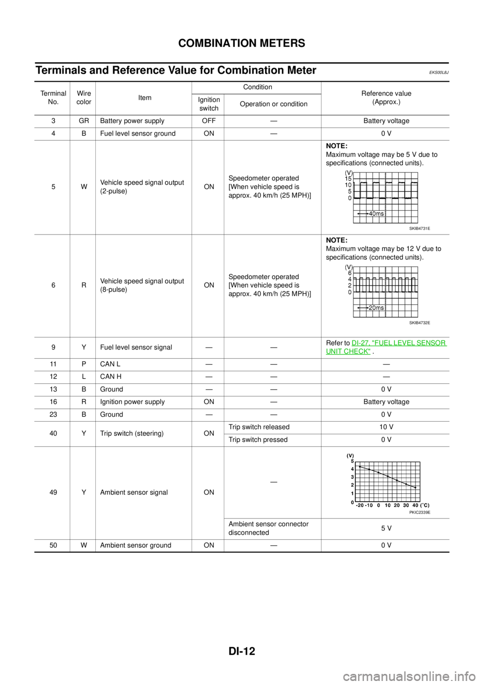
COMBINATION METERS
Terminals and Reference Value for Combination Meter
EKS00L8J
Te r m i n a l
No.Wire
colorItemCondition
Reference value
(Approx.) Ignition
switchOperation or condition
3 GR Battery power supply OFF — Battery voltage
4 B Fuel level sensor ground ON — 0 V
5WVehicle speed signal output
(2-pulse)ONSpeedometer operated
[When vehicle speed is
approx. 40 km/h (25 MPH)]NOTE:
Maximum voltage may be 5 V due to
specifications (connected units).
6RVehicle speed signal output
(8-pulse)ONSpeedometer operated
[When vehicle speed is
approx. 40 km/h (25 MPH)]NOTE:
Maximum voltage may be 12 V due to
specifications (connected units).
9 Y Fuel level sensor signal — —Refer toDI-27, "
FUEL LEVEL SENSOR
UNIT CHECK".
11 P C A N L — — —
12 L CAN H — — —
13 B Ground — — 0 V
16 R Ignition power supply ON — Battery voltage
23 B Ground — — 0 V
40 Y Trip switch (steering) ONTrip switch released 10 V
Trip switch pressed 0 V
49 Y Ambient sensor signal ON—
Ambient sensor connector
disconnected5V
50 W Ambient sensor ground ON — 0 V
SKIB4731E
SKIB4732E
PKIC2339E
Page 983 of 3171

EC-3
C
D
E
F
G
H
I
J
K
L
M
ECA Component Inspection ......................................... 158
Removal and Installation ...................................... 158
DTC P0335 CKP SENSOR ..................................... 159
Description ........................................................... 159
CONSULT-II Reference Value in Data Monitor Mode
. 159
ECM Terminals and Reference Value .................. 159
On Board Diagnosis Logic ................................... 160
DTC Confirmation Procedure ............................... 160
Wiring Diagram .................................................... 161
Diagnostic Procedure ........................................... 162
Component Inspection ......................................... 164
Removal and Installation ...................................... 164
DTC P0336 CKP SENSOR ..................................... 165
Description ........................................................... 165
CONSULT-II Reference Value in Data Monitor Mode
. 165
ECM Terminals and Reference Value .................. 165
On Board Diagnosis Logic ................................... 166
DTC Confirmation Procedure ............................... 166
Wiring Diagram .................................................... 167
Diagnostic Procedure ........................................... 168
Component Inspection ......................................... 170
Removal and Installation ...................................... 170
DTC P0340 CMP SENSOR .................................... 171
Description ........................................................... 171
ECM Terminals and Reference Value .................. 171
On Board Diagnosis Logic ................................... 172
DTC Confirmation Procedure ............................... 172
Wiring Diagram .................................................... 173
Diagnostic Procedure ........................................... 174
Component Inspection ......................................... 175
Removal and Installation ...................................... 176
DTC P0341 CMP SENSOR .................................... 177
Description ........................................................... 177
ECM Terminals and Reference Value .................. 177
On Board Diagnosis Logic ................................... 178
DTC Confirmation Procedure ............................... 178
Wiring Diagram .................................................... 179
Diagnostic Procedure ........................................... 180
Component Inspection ......................................... 182
Removal and Installation ...................................... 182
DTC P0501 ASCD VEHICLE SPEED SENSOR .... 183
Component Description ........................................ 183
On Board Diagnosis Logic ................................... 183
DTC Confirmation Procedure ............................... 183
Diagnostic Procedure ........................................... 184
DTC P0502 ASCD VEHICLE SPEED SENSOR .... 185
Component Description ........................................ 185
On Board Diagnosis Logic ................................... 185
DTC Confirmation Procedure ............................... 185
Diagnostic Procedure ........................................... 186
DTC P0503 ASCD VEHICLE SPEED SENSOR .... 187
Component Description ........................................ 187
On Board Diagnosis Logic ................................... 187
DTC Confirmation Procedure ............................... 187
Diagnostic Procedure ........................................... 188
DTC P0504 ASCD BRAKE SWITCH ..................... 189
Component Description ........................................ 189CONSULT-II Reference Value in Data Monitor Mode
.189
ECM Terminals and Reference Value ...................189
On Board Diagnosis Logic ....................................190
DTC confirmation Procedure ................................190
Wiring Diagram .....................................................192
Diagnostic Procedure ...........................................193
Component Inspection ..........................................202
DTC P0563 BATTERY VOLTAGE ..........................203
On Board Diagnosis Logic ....................................203
DTC Confirmation Procedure ...............................203
Diagnostic Procedure ...........................................203
DTC P0580, P0581 ASCD STEERING SWITCH ....206
Component Description ........................................206
CONSULT-II Reference Value in Data Monitor Mode
.206
ECM Terminals and Reference Value ...................206
On Board Diagnosis Logic ....................................207
DTC Confirmation Procedure ...............................207
Wiring Diagram .....................................................208
Diagnostic Procedure ...........................................209
Component Inspection ..........................................212
DTC P0605 ECM .....................................................213
Description ............................................................213
On Board Diagnosis Logic ....................................213
DTC Confirmation Procedure ...............................213
Diagnostic Procedure ...........................................214
DTC P0606 ECM .....................................................215
Description ............................................................215
On Board Diagnosis Logic ....................................215
DTC Confirmation Procedure ...............................215
Diagnostic Procedure ...........................................216
DTC P0628, P0629 FUEL PUMP ............................217
Description ............................................................217
CONSULT-II Reference Value in Data Monitor Mode
.217
ECM Terminals and Reference Value ...................217
On Board Diagnosis Logic ....................................218
DTC Confirmation Procedure ...............................218
Wiring Diagram .....................................................219
Diagnostic Procedure ...........................................220
Component Inspection ..........................................221
Removal and Installation ......................................221
DTC P0642, P0643 SENSOR POWER SUPPLY ....222
ECM Terminals and Reference Value ...................222
On Board Diagnosis Logic ....................................222
DTC Confirmation Procedure ...............................223
Wiring Diagram .....................................................224
Diagnostic Procedure ...........................................225
DTC P0652, P0653 SENSOR POWER SUPPLY ....227
ECM Terminals and Reference Value ...................227
On Board Diagnosis Logic ....................................228
DTC Confirmation Procedure ...............................228
Wiring Diagram .....................................................229
Diagnostic Procedure ...........................................230
DTC P0686 ECM RELAY ........................................232
ECM Terminals and Reference valve ...................232
On Board Diagnosis Logic ....................................232
DTC Confirmation Procedure ...............................232
Page 998 of 3171

EC-18
ENGINE CONTROL SYSTEM
System Chart
EBS01KCD
*1: The input signal is sent to the ECM through CAN communication line.
*2: The output signal is sent from the ECM through CAN communication line.
Fuel Injection Control SystemEBS01KCE
SYSTEM DESCRIPTION
Three types of fuel injection control are provided to accommodate engine operating conditions; normal control,
idle control and start control. The ECM determines the appropriate fuel injection control. Under each control,
the amount of fuel injected is adjusted to improve engine performance.
Pulse signals are sent to fuel injectors according to the input signals to adjust the amount of fuel injected to
preset value.
START CONTROL
Input/Output Signal Chart
Input (Sensor) ECM Function Output (Actuator)
lAccelerator pedal position sensor
lFuel rail pressure sensor
lFuel pump temperature sensor
lEngine coolant temperature sensor
lMass air flow sensor
lIntake air temperature sensor
lCrankshaft position sensor
lCamshaft position sensor
lTurbocharger boost sensor
lWheel sensor*1
lIgnition switch
lASCD steering switch
lASCD brake switch
lASCD clutch switch
lSt o p l a m p s w it c h
lAir conditioner switch*1
lFront air control*1
lPark/neutral position switch
lHeat up switch
lRefrigerant pressure sensor
lBattery voltageFuel injection control Fuel injector and Fuel pump
Fuel injection timing control Fuel injector and Fuel pump
Fuel cut control Fuel injector and Fuel pump
Glow control system
Glow relay and glow indicator lamp*
2
ASCD vehicle speed control Fuel injector and Fuel pump
On board diagnostic system
Malfunction indicator (MI)*
2
EGR volume control EGR volume control valve
Cooling fan control
Cooling fan relay*
2
Turbocharger boost controlTurbocharger boost control solenoid
valve
Intake air control valve controlIntake air control valve control solenoid
valve
Air conditioning cut control
Air conditioner relay*
2
Sensor Input Signal to ECM ECM Function Actuator
Engine coolant temperature sensor Engine coolant temperature
Fuel injection
control (start
control)Fuel injector
Fuel pump Crankshaft position sensor Engine speed
Camshaft position sensor Piston position
Ignition switch Start signal
Fuel rail pressure sensor Fuel rail pressure